Essential Safety Guidelines for Grinding and Cutting (Guide)
I have spent the better part of two decades in fabrication shops, often arriving when things have already gone wrong. My job is to figure out why a spindle is vibrating, why a weld is failing, or why a tool is behaving unpredictably. In my experience, the most dangerous moments in a shop do not usually come from a lack of effort. They come from a lack of systematic observation. When we pick up a handheld grinder or a cutoff tool, we are holding a motor capable of spinning an abrasive disc at over 10,000 revolutions per minute. At those speeds, a minor mechanical oversight becomes a major structural failure.
I remember a specific case in a custom trailer shop a few years back. The lead fabricator was complaining about “bad batches” of cutting wheels. They were shattering mid-cut, causing downtime and near-misses. After spending a morning observing their process, I realized it wasn’t the wheels at all. It was a combination of worn-out spindle flanges and improper workholding that was introducing side-load stresses the wheels weren’t designed to handle. This guide is built on those kinds of lessons. We are going to look at the technical mechanics of abrasive tools through the lens of a diagnostic specialist.
Establishing a Systematic Diagnostic Framework for Abrasive Tools
A systematic diagnostic framework is a structured method for evaluating equipment health by isolating variables like mechanical wear, mounting errors, and material resistance. It ensures that every time you pull the trigger, the tool performs within its engineered safety envelope.
Before you even plug in a tool, you have to treat it like a machine tool, not just a hand tool. I use a three-step process: observation, isolation, and verification. First, observe the tool’s physical condition. Second, isolate the components—the motor, the spindle, the flanges, and the abrasive. Third, verify that the specs of the abrasive match the capabilities of the tool.
If you feel an unusual vibration, do not just push through it. Stop and ask: Is the vibration coming from the motor bearings, an unbalanced wheel, or a bent spindle? By breaking the tool down into these sub-systems, you can find the root cause of a problem before it leads to a failure. This analytical approach turns safety from a list of rules into a technical standard of operation.
Mechanical Inspection and Spindle Integrity
Mechanical inspection is the process of verifying that the rotating components of a power tool, specifically the spindle and flanges, meet original manufacturing tolerances. This prevents eccentric rotation which causes uneven wear and catastrophic wheel breakage.
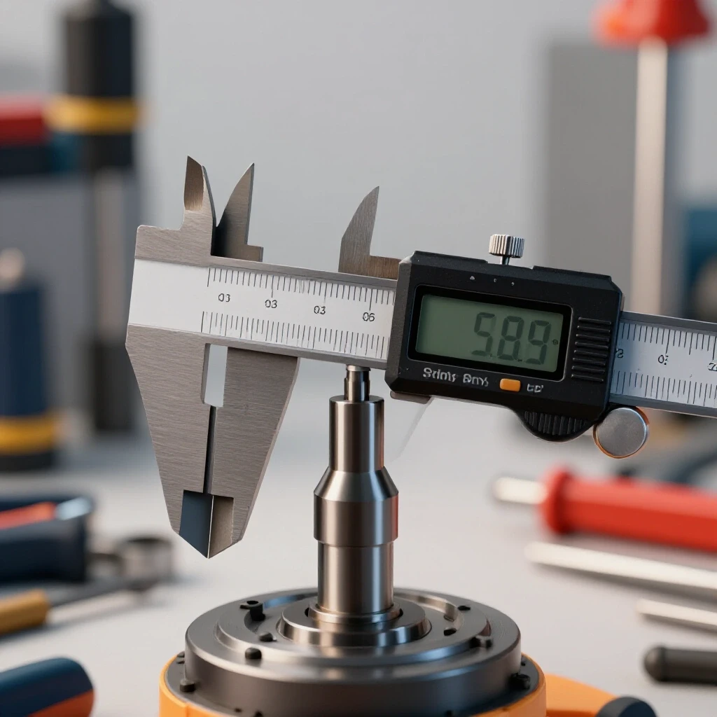
The spindle is the heart of any grinding or cutting operation. If the spindle is bent, even by a few thousandths of an inch, the centrifugal force at high RPM will be uneven. I always check for spindle runout using a dial indicator if a tool has been dropped or shows signs of heavy wear. A runout of more than 0.003 inches is usually enough to cause noticeable chatter and should be addressed.
The flanges—the two metal plates that sandwich the wheel—are equally critical. They must be clean, flat, and the same diameter. I often see shops using mismatched flanges or flanges that have been deformed by over-tightening. If the flange is warped, it applies uneven pressure to the abrasive disc. This creates a stress riser in the fiberglass reinforcement of the wheel. When you apply pressure to the cut, that stress riser becomes the point where the wheel cracks.
Grinder Component Diagnostic Benchmarks
| Component | Inspection Point | Tolerance/Standard |
|---|---|---|
| Spindle | Radial Runout | Less than 0.003 inches |
| Flanges | Flatness | No visible light under a machinist straightedge |
| Bearings | Play/Movement | Zero axial or radial “slop” |
| Cord/Power | Resistance | Less than 1.0 Ohm on the ground pin |
| Guard | Positioning | Must cover at least 180 degrees of the wheel |
Analyzing Abrasive Wheel Integrity and Mounting Standards
Abrasive wheel integrity refers to the structural soundness of a cutting or grinding disc, ensuring it is free from internal cracks and is rated for the specific RPM of the power tool. Proper mounting ensures the wheel is centered and secured without being crushed.
Every time I pick up a new wheel, I perform a “ring test” if it is a vitrified bond wheel, or a close visual inspection for reinforced resinoid wheels. For the ring test, you tap the wheel lightly with a non-metallic object. A sound wheel will have a clear metallic ring; a cracked one will thud. While this is less common for thin “zip” discs, checking for nicks on the edges is mandatory.
The RPM rating is a hard limit, not a suggestion. I have seen fabricators put a 7-inch wheel on a 5-inch grinder by removing the guard. This is a recipe for disaster. A 5-inch grinder often spins at 11,000 RPM, while a 7-inch wheel might only be rated for 8,500 RPM. The centrifugal force increases with the square of the speed. Running that larger wheel over its limit can cause it to literally explode under its own weight.
- Check the “use-by” date on the center ring of the wheel; resins can degrade over time.
- Ensure the blotter (the paper washer) is intact; it helps distribute flange pressure.
- Tighten the nut firmly but avoid using an impact wrench or excessive force.
- Verify the wheel hole size matches the spindle shoulder perfectly to prevent eccentricity.
Diagnosing Excessive Vibration and Tool Chatter
Tool chatter is a high-frequency vibration caused by the resonant interaction between the abrasive wheel and the workpiece, often resulting from improper pressure or mechanical instability. It ruins surface finish and can lead to tool failure.
When I hear a tool “singing” or feel a rhythmic bounce, I know I am dealing with harmonics. Chatter is often caused by the wheel being “out of round” or the operator using too little pressure, allowing the wheel to skip across the surface. If the wheel is out of round, you can sometimes “dress” a grinding stone to true it up, but with thin cutting wheels, you simply have to replace them.
Another cause of chatter is bearing failure. If the bearings in the gear head have even 0.005 inches of play, the spindle will wobble under load. This wobble creates a feedback loop of vibration. To diagnose this, I unplug the tool and try to move the spindle side-to-side by hand. Any perceptible movement means the bearings are shot. Replacing bearings is a precision task, but it is cheaper than a new tool and far safer than running a vibrating machine.
Strategic Workholding and Stress Management
Workholding is the method of securing a workpiece to prevent movement and manage the internal mechanical stresses that are released during metal removal. Proper workholding prevents the material from “pinching” the cutting tool.
One of the most common causes of kickback is “binding.” This happens when the metal you are cutting moves and pinches the wheel in the kerf. As a diagnostic specialist, I look at the “load path” of the material. If you are cutting a piece of angle iron supported at both ends, the middle will sag as the cut progresses, pinching the wheel.
I always teach fabricators to support the material so the cut opens up as they go. This is called “cutting on the tension side.” By managing how the metal moves, you eliminate the force that causes the tool to jerk out of your hands. If the material is too heavy to move, use wedges to keep the kerf open.
- Use at least two points of contact for clamping whenever possible.
- Avoid cutting material that is under spring tension unless it is fully restrained.
- Position yourself so that if the tool does kick back, it moves away from your body.
- Never use your foot or hand as a “clamp” for the workpiece.
Workspace Management and Protective Gear
Workspace management involves controlling the environment to mitigate risks from sparks, dust, and debris, while PPE provides the final layer of defense against mechanical hazards.
I have seen many fires started by a grinder spark that smoldered in a pile of oily rags for twenty minutes before igniting. A systematic approach to the workspace means clearing a “spark zone” of at least 10 to 15 feet. I also look at the direction of the spark stream. You should always aim sparks away from yourself, other people, and flammable materials like gas cylinders or hoses.
Regarding PPE, I treat it as a technical requirement. Safety glasses are for impact, but a full-face shield is for the “what if” scenario of a wheel burst. I have seen a face shield save a man’s jaw when a 4.5-inch disc shattered. Hearing protection is also non-negotiable. The high-pitched whine of a grinder can reach 105 decibels, which can cause permanent hearing damage in minutes.
- Wear a face shield over safety glasses for maximum impact protection.
- Use flame-resistant clothing; synthetic fibers like polyester can melt to your skin.
- Ensure your gloves are snug; loose material can get caught in the rotating spindle.
- Use a respirator or high-quality dust mask when grinding materials like stainless steel or galvanized metal to avoid inhaling toxic dust.
Case Study: The Mystery of the “Walking” Cut
I was once called to a shop where they were struggling with precision cuts on 1/2-inch plate. The cuts were “walking”—drifting off the line and creating a beveled edge. The operator thought the tools were underpowered.
Upon inspection, I found the issue wasn’t power; it was a combination of vibration and poor wheel selection. They were using a grinding disc to do a cutting job, which created too much heat and surface area resistance. This caused the spindle to deflect under the pressure the operator was forced to apply.
We switched to a dedicated 0.045-inch thin cutting wheel, verified the spindle runout was within 0.002 inches, and adjusted the workholding to prevent the plate from vibrating. The “walking” stopped immediately. The lesson here is that when a tool isn’t performing, look at the physics of the interface between the abrasive and the metal.
Tool Maintenance and Calibration Checklist
To keep your equipment in top shape, I recommend a weekly maintenance routine. This isn’t just about cleaning; it’s about verifying the mechanical integrity of your primary fabrication tools.
- Spindle Check: Spin the spindle by hand to feel for “grittiness” in the bearings.
- Flange Inspection: Remove the flanges and clean them with a wire brush. Check for burrs or warping.
- Guard Verification: Ensure the guard is tight and can be adjusted without tools if it’s a quick-release model.
- Brush Inspection: If the tool has a brushed motor, check the carbon brushes. If they are worn to less than 1/4 inch, replace them to prevent motor arcing.
- Cord Integrity: Run your hand down the power cord to feel for internal breaks or nicks in the insulation.
- Speed Verification: Occasionally use a non-contact tachometer to ensure the motor isn’t over-speeding beyond its factory rating.
Troubleshooting Common Abrasive Issues
| Symptom | Probable Cause | Diagnostic Action |
|---|---|---|
| Excessive Vibration | Unbalanced wheel or bent spindle | Replace wheel; check spindle with dial indicator |
| Wheel Glazing (Shiny surface) | Using a wheel that is too “hard” for the metal | Switch to a softer bond wheel or increase pressure |
| Rapid Wheel Wear | Using a wheel that is too “soft” or excessive RPM | Check RPM match; switch to a harder bond wheel |
| Discoloration of Metal (Blueing) | Excessive heat buildup | Use less pressure; switch to a thinner cutting disc |
| Tool Overheating | Clogged cooling vents or worn brushes | Blow out vents with compressed air; check brushes |
Conclusion
Mastering the use of abrasive tools is about more than just muscle; it is about understanding the mechanical limits of your equipment. By applying a systematic diagnostic approach—checking your spindle tolerances, verifying wheel ratings, and managing the stresses in your material—you turn a potentially hazardous task into a controlled, professional process.
The most successful fabricators I know are the ones who stop when something feels “off.” They don’t view a vibrating tool as an annoyance; they view it as a data point indicating a mechanical failure. Take the time to calibrate your tools and your workspace. It will not only make your shop safer but will also improve the quality of your cuts and the longevity of your equipment. Your next step should be a thorough audit of your current tool inventory using the benchmarks provided in this guide.
FAQ
Why does my cutting wheel keep jumping out of the kerf when I start a cut? This is usually caused by “climb cutting” or starting with too much pressure. If the wheel rotation is pulling the tool toward you, it can easily climb out of the groove. Start the cut on the far side of the material and pull the tool toward you, or ensure you are making a shallow “score” line first to guide the wheel.
How tight should I actually get the spindle nut? The nut should be “snug.” Most grinders are designed so that the rotation of the motor naturally tightens the nut during use. Over-tightening with a wrench can crack the hub of the wheel or warp the flanges, leading to the vibration issues we discussed earlier. Hand-tight plus a quarter turn with the spanner is usually sufficient.
Can I use a grinding wheel to cut through thin sheet metal? It is not recommended. Grinding wheels are designed for peripheral or face grinding and are much thicker. Using them to cut creates excessive heat and friction, which can lead to “blueing” of the metal and potential wheel failure due to side-loading. Always use a dedicated thin cutting disc for slicing through material.
What is the difference between a Type 27 and a Type 1 wheel? A Type 27 wheel has a depressed center, allowing the nut to be recessed so you can grind flat against a surface. A Type 1 wheel is flat. Type 1 wheels are almost exclusively for cutting, while Type 27 can be found in both grinding and cutting configurations. Using a Type 1 for surface grinding is dangerous because it lacks the structural reinforcement for side-pressure.
How do I know if my grinder bearings are failing? Listen for a high-pitched “screaming” sound that changes in pitch when you tilt the tool. Also, check for heat. If the gear head becomes too hot to touch after only a minute of use, the bearings are likely failing and creating excessive friction.
Is it safe to use a wheel if the edges are slightly chipped? No. A chip in the edge of an abrasive wheel is a structural defect. At high RPM, that chip can act as a starting point for a crack that travels through the entire wheel. It also causes significant imbalance and vibration.
Why does my grinder lose power when I push down on it? This is often a sign of worn carbon brushes or a failing capacitor. It could also mean you are using an extension cord that is too long or too thin, causing a “voltage drop.” Ensure you are using a 12-gauge or 14-gauge cord for high-amp tools.
What should I do if a wheel bursts while I’m using it? Immediately release the trigger and unplug the tool. Do not attempt to inspect the tool while it is still powered. Once safe, inspect the guard, flanges, and spindle for damage. A wheel burst often bends the spindle, making the tool unsafe for future use until repaired.
Can I grind aluminum with a standard steel grinding wheel? You should not. Aluminum is a soft, “gummy” metal that will “load” the wheel, filling the pores of the abrasive with molten metal. This stops the wheel from cutting and can lead to rapid heat buildup and wheel explosion. Use wheels specifically labeled for non-ferrous metals or aluminum.
How often should I replace my grinder’s flanges? Inspect them every time you change a wheel. If you see any rounding of the edges, visible warping, or if the “keyway” that locks it to the spindle is wallowed out, replace them immediately. They are inexpensive compared to the cost of a failed tool.
(This article was written by one of our staff writers, Paul Whitaker. Visit our Meet the Team page to learn more about the author and their expertise.)