Feed and Speed Rate Calculator Chart for Mild Steel (Guide)
The transition from a crowded garage to a high-output fabrication shop is rarely a straight line. I remember the exact moment I realized my old way of working was failing. I had just landed a contract for fifty structural brackets, and my shop floor looked like a maze of tangled cords and metal scraps. I was spending more time moving material than actually cutting it. Over the last 20 years, I have learned that scaling up is not about buying bigger tools; it is about engineering a system where those tools can actually perform.
When you move into advanced fabrication, you stop guessing and start calculating. You move from “feeling” how a tool cuts to using precise data to drive your spindle and gantry. This shift requires a total rethink of your workshop layout, your power delivery, and how you manage the air you breathe. It is a transition from being a maker to being a manufacturing engineer.
Mapping Material-Flow Loops and Floor Capacity
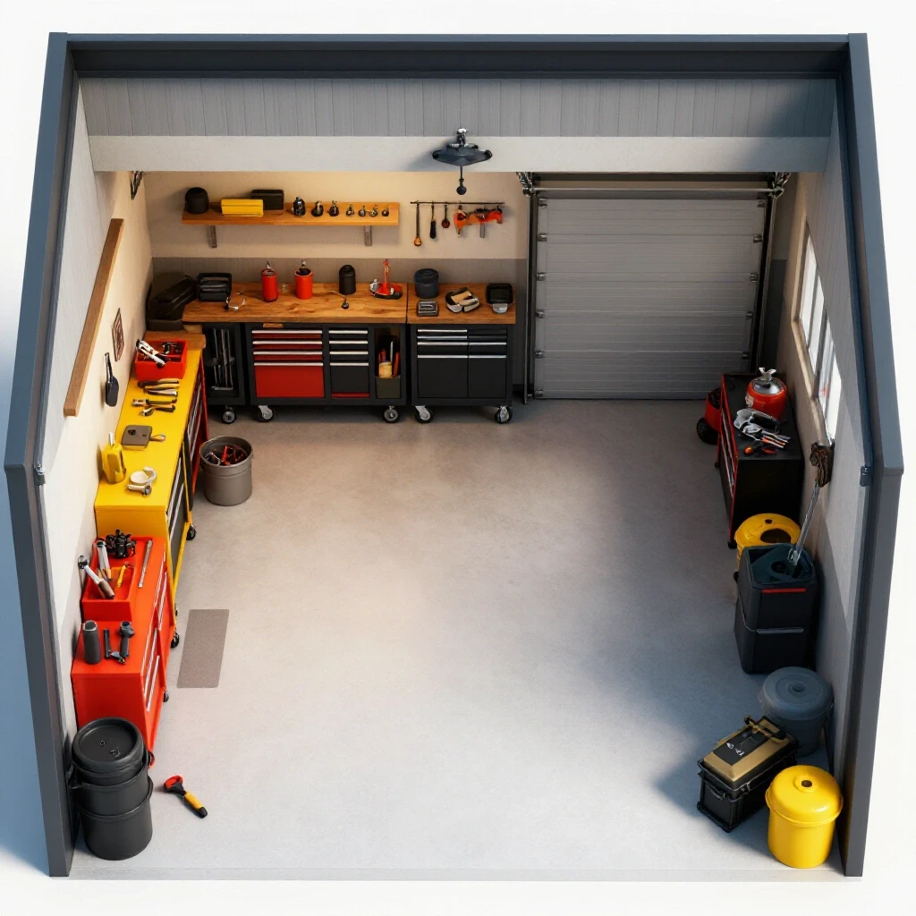
Advanced workshop layout planning is the process of organizing equipment to minimize the physical distance a part travels during production. By analyzing the “travel loop” of a sheet of mild steel, you can identify bottlenecks that slow down your throughput. A good layout respects the weight of the material and the limits of the floor.
In my early years, I placed my heavy equipment wherever there was an open outlet. This was a mistake. I ended up moving heavy 4×8 sheets of carbon steel across the entire shop just to reach the CNC table. Now, I follow a linear flow pattern. Material comes in at one end, moves to the cutting station, then to secondary operations, and finally to the shipping area.
You must also consider your floor load ratings. A full pallet of mild steel can weigh several thousand pounds. If your concrete slab is only four inches thick, you might see cracking under the weight of a heavy CNC gantry and material rack. I recommend a minimum of a six-inch reinforced slab for areas where you plan to store bulk steel or run large-scale machinery.
| Layout Type | Material Travel Distance | Efficiency Rating | Best Use Case |
|---|---|---|---|
| Random Placement | High (100+ ft) | Low | Hobby/Repair |
| U-Shaped Flow | Medium (50-60 ft) | High | Small Commercial |
| Linear Flow | Low (20-30 ft) | Very High | High-Volume Production |
Powering the Evolution: 3-Phase Electrical Loads and Conversion
A 3-phase power converter is a device that transforms standard residential single-phase electricity into the three-phase power required by industrial-grade motors. This is a critical upgrade for any fabricator moving toward professional CNC equipment. It provides more consistent torque and allows for the use of more efficient, durable motors.
When I first integrated a CNC system, I struggled with the electrical supply. Most home shops are limited to 200 amps of single-phase power. To run a high-duty cycle spindle or a large air compressor, you often need three-phase power. I chose a rotary phase converter because it handles the high inrush current of starting large motors better than static converters.
The National Electrical Code (NEC) has specific frameworks for these installations. You must ensure your phase balance—the voltage difference between the three legs—is within 2% to 5%. If the phases are unbalanced, your motors will run hot and fail prematurely. I suggest using a smart phase-angle controller to monitor this balance in real-time, especially when running sensitive CNC electronics.
- Rotary Phase Converter: Best for varying loads and high-torque starts.
- Digital Phase Converter: Provides the cleanest power for CNC controllers.
- Static Converter: Only useful for fixed loads; generally not recommended for CNC.
High-Volume Air Filtration and Dust Collection Duct Design
Dust collection duct design involves calculating the necessary air velocity to keep metal particles moving through a pipe system without settling. For metalworking, this usually requires a “carrying velocity” of at least 3,500 to 4,500 feet per minute. Proper filtration protects both your lungs and your expensive machinery from abrasive grit.
I once thought a standard shop vac was enough for my grinding station. I was wrong. The fine dust from mild steel fabrication is heavy and abrasive. It gets into the bearings of your CNC gantry and ruins them. I eventually moved to a multi-stage cyclone dust collection system. This system separates the heavy chips before the air reaches the final HEPA filters.
When designing your ducts, you must account for static pressure loss. Every bend and every foot of pipe creates resistance. If your duct runs are too long or have too many elbows, your CFM (cubic feet per minute) will drop. I aim for at least 1,000 CFM at the source for a single CNC station.
| Tool Type | Required CFM | Ideal Duct Diameter | Static Pressure Goal |
|---|---|---|---|
| CNC Plasma Table | 1,200 – 1,500 | 6 – 8 inches | 4.0 “wg |
| Grinding Station | 500 – 800 | 4 – 5 inches | 3.5 “wg |
| Large Band Saw | 400 – 600 | 4 inches | 3.0 “wg |
Optimizing CNC Gantry Systems for Mild Steel Throughput
Scaling fabrication shop operations depends heavily on how well you integrate your CNC gantry with your material workflow. This involves more than just bolting a machine to the floor. It requires a stable, level base and a clear understanding of the mechanical limits of your stepper or servo motors.
In my shop, I found that machine leveling was the most overlooked step. If the gantry is not perfectly square and level, your cuts in mild steel will have a slight taper. This might not matter for a hobby project, but for professional parts, it leads to assembly issues. I use precision machinist levels to check the rails every six months.
The choice between stepper motors and servo motors is also vital. Steppers are cost-effective but can lose their position if they hit an obstacle. Servos use closed-loop feedback encoders, meaning the machine always knows exactly where it is. For high-output shops, the extra cost of servos is usually recovered through reduced scrap and faster travel speeds.
Calculating Rotational Speeds and Linear Travel for Carbon Steel
Understanding the relationship between surface feet per minute (SFM) and chip load is the key to efficient metal removal. SFM refers to how fast the cutting edge moves across the material, while chip load is the thickness of the material removed by each tooth of the cutter. These two numbers dictate your spindle RPM and your feed rate.
When I work with mild steel, I start with the material’s hardness. For standard low-carbon plate, I typically target an SFM of 60 to 120 when using High-Speed Steel (HSS) tools. If I am using carbide tooling, I can push that much higher, often between 200 and 400 SFM. This speed allows the tool to cut cleanly without generating excessive heat that would dull the edge.
To find the spindle RPM, I use the formula: (SFM x 3.82) / Tool Diameter. Once the RPM is set, I calculate the linear feed rate by multiplying the RPM by the number of teeth on the cutter and the desired chip load. For mild steel, a chip load of 0.001 to 0.012 inches per tooth is common, depending on the tool’s rigidity and the depth of the cut.
- HSS Tooling SFM: 60 – 120
- Carbide Tooling SFM: 200 – 400
- Chip Load Range: 0.001″ – 0.012″ per tooth
- Rigidity Factor: Lower feed rates for long, thin tools; higher for short, stubby ones.
Managing Tooling Files and Workflow Optimization Tips
Workflow optimization tips often center on the digital side of the shop. Managing your CAD/CAM integration is just as important as managing your physical tools. This involves creating a library of “proven” cutting parameters for different thicknesses of mild steel so you don’t have to recalculate every time you start a new job.
I keep a digital log of every job I run. If I find that a specific feed rate produced a perfect finish on 1/4-inch plate, I save that as a template in my CAM software. This reduces setup times significantly. Instead of spending twenty minutes dialing in settings, I can load the file and start cutting in seconds.
Modern cloud-based ERP (Enterprise Resource Planning) systems can also help. These tools track your material inventory and the time spent on each machine. By looking at the data, I realized that my biggest time-sink wasn’t the cutting itself, but the time spent looking for the right size of mild steel remnants. Organizing my material rack by thickness saved me hours every week.
- Standardize Tooling: Use the same few end mills or nozzles to simplify calculations.
- Document Everything: Record the RPM, feed rate, and results for every new thickness.
- Optimize Nesting: Use software to fit as many parts as possible on a single sheet.
- Batch Processing: Run all parts of the same thickness at once to minimize tool changes.
Actionable Benchmarks for System Commissioning
When you bring a new CNC system online, you need a way to measure success. I use a series of commissioning runs to verify that my calculations are translating to the real world. This involves cutting a test pattern in a piece of scrap mild steel and measuring the results with calipers.
First, I check the dimensional accuracy. If a 2-inch square comes out at 1.98 inches, I know my steps-per-inch settings are off. Second, I look at the surface finish. If the edges are ragged, my SFM might be too high, or my feed rate might be too slow, causing the tool to rub rather than cut.
Finally, I monitor the electrical load during the cut. If the spindle motor is pulling more amps than it is rated for, I am pushing the tool too hard. I keep a phase balancing log to ensure that the 3-phase converter is maintaining stable voltage under load. These benchmarks ensure that the shop is running at peak efficiency without risking equipment damage.
- Dimensional Tolerance: Goal of +/- 0.005 inches for most fabrication.
- Surface Finish: Smooth to the touch, no visible “chatter” marks.
- Electrical Stability: Phase voltage stays within 5% of the target.
- Maintenance Interval: Clean filters every 40 hours of operation; grease rails weekly.
Conclusion
Transitioning to a semi-professional shop is a journey of constant refinement. It starts with a smart layout that respects the flow of material and ends with precise calculations that maximize the life of your tools. By focusing on the physics of the cut and the efficiency of your power and air systems, you can move past the bottlenecks that hold most shops back. The goal is not just to work faster, but to work with a level of predictability that allows your business or your craft to grow. Take it one step at a time: fix your floor plan, stabilize your power, and then master your cutting data.
FAQ
What is the best way to determine the feed rate for a new thickness of mild steel? Start with the manufacturer’s recommended SFM (Surface Feet per Minute) for the tool material. Use the formula (SFM x 3.82) / Diameter to find your RPM. Then, multiply that RPM by the number of teeth and a conservative chip load, such as 0.002 inches. Run a test cut and increase the feed rate gradually until the cut quality is optimal.
How does tool diameter affect the RPM calculation for carbon steel? Smaller tools must spin much faster than larger tools to achieve the same surface speed. For example, a 1/4-inch end mill needs four times the RPM of a 1-inch end mill to reach the same SFM. Always calculate RPM based on the specific diameter of the tool you are using to avoid burning the tool or breaking it.
Why is chip load so important when cutting mild steel? Chip load ensures that the tool is actually removing metal rather than just rubbing against it. Rubbing creates friction and heat, which dulls the cutting edge almost instantly. A proper chip load also carries the heat away from the part and into the chip itself, keeping the tool and the workpiece cooler.
What are the signs that my feed rate is too slow? If you see blue or discolored chips, or if the tool is making a high-pitched squealing sound, your feed rate is likely too slow. This causes the tool to “rub,” generating excessive heat. You may also notice a very shiny, but slightly smeared, surface finish on the mild steel.
Can I run a CNC spindle on a single-phase 220V circuit? Small spindles (under 2.2kW) can often run on single-phase power using a Variable Frequency Drive (VFD). However, larger, industrial-grade spindles usually require 3-phase power. Using a rotary or digital phase converter is the most reliable way to provide this power in a home-based or light commercial shop.
How often should I balance the phases on my rotary converter? You should check the voltage balance whenever you add a new machine to the circuit or if you notice your motors are running unusually hot. Ideally, you want to see less than a 5% difference between the three legs of power while the machine is under a typical working load.
What is the minimum CFM I need for a CNC plasma table? A standard 4×4 or 4×8 plasma table generally requires between 1,000 and 1,500 CFM to effectively capture fumes. This depends on whether you are using a water table or a downdraft system. Downdraft systems usually require higher CFM to overcome the resistance of the table’s internal structure.
How do I calculate static pressure loss in my shop’s ductwork? Static pressure loss is calculated by adding the resistance of every foot of straight pipe, every elbow, and every transition. Most fabricators use a “static pressure loss chart” which provides values like “0.05 inches of loss per 10 feet of 6-inch pipe.” Totaling these values tells you if your fan has enough power to pull air through the entire system.
What is the difference between SFM and RPM? SFM (Surface Feet per Minute) is a constant value based on the material being cut. It describes how fast the tool’s edge travels. RPM (Revolutions Per Minute) is a variable value that you change based on the tool’s diameter to achieve that target SFM. Think of SFM as the “speed limit” for the material and RPM as the “speedometer” on your machine.
Why should I avoid using em dashes in my workshop documentation? While not related to the physics of cutting, standardizing your documentation—using simple bullets or hyphens—makes it easier for different software systems to read and display your tool libraries and setup notes. Consistency in data entry prevents errors when importing files into different CAM or ERP platforms.
(This article was written by one of our staff writers, Edward Sinclair. Visit our Meet the Team page to learn more about the author and their expertise.)