How to Nest Odd-Shaped Metal Parts on Sheet Layouts (Guide)
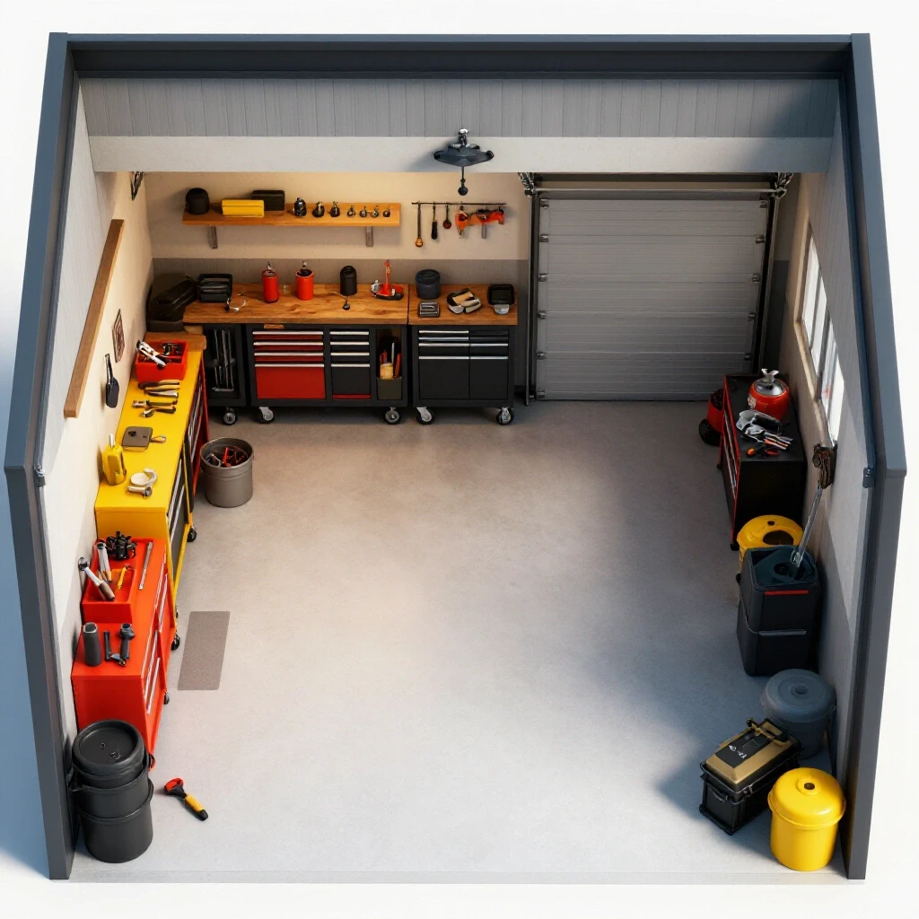
Twenty years ago, I stood in a 400-square-foot garage, staring at a single sheet of 10-gauge mild steel. I had six complex, interlocking brackets to cut, and that sheet was the last one in the rack. If I messed up the arrangement, the project was dead until the next delivery. That night taught me that scaling a fabrication business isn’t just about buying faster machines; it is about mastering the physics of your floor space and the geometry of your material.
As we move from hobbyist setups to professional production, the challenges change. You stop worrying about whether the machine will turn on and start worrying about material-flow bottlenecks and the high cost of wasted plate. Transitioning to a high-output environment requires a systematic approach to how we place irregular geometries on a flat surface to minimize scrap and maximize throughput.
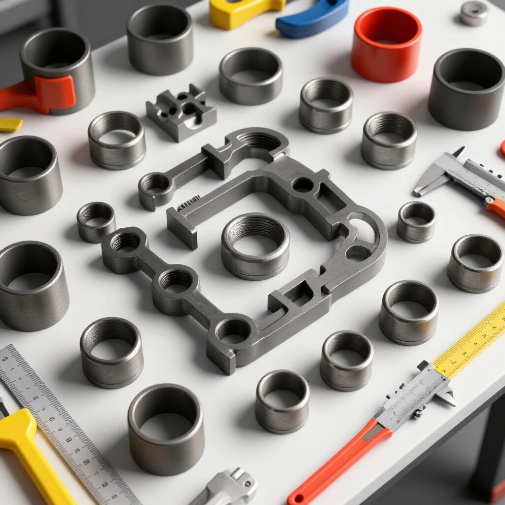
Mapping Material-Flow Loops and Machine Zoning
Material-flow loops are the predetermined paths that raw stock, work-in-progress, and finished parts take through your shop. Mapping these loops helps identify where physical bottlenecks occur, such as when a 4×8 sheet must be flipped in a narrow hallway.
When I redesigned my current facility, I realized that my CNC plasma table setup was positioned in a “dead zone.” Every time I needed to load a heavy sheet, I had to move two rolling carts and a welding table. By applying lean manufacturing principles, I moved to a linear flow pattern. Now, material enters the rear door, moves directly to the material rack, slides onto the cutting bed, and exits toward the grinding station.
- Machine Spacing Boundaries: Maintain a 3-foot minimum access zone around all sides of your CNC table. This ensures you can service the gantry and clear “tip-ups” without hitting a wall.
- Zoning: Group your “hot work” (cutting and welding) away from “clean work” (assembly and electronics). This reduces the risk of grinding dust infiltrating your CNC controller.
- Travel Waste: Every foot a technician walks to move a part is a hidden cost. Aim for a “point-of-use” storage system where the most common sheet thicknesses are stored within arm’s reach of the table.
Measuring Floor Capacities and Structural Loading
Floor load ratings represent the maximum weight a shop floor can safely support per square foot. Most residential garage slabs are 4 inches thick, which generally supports 3,000 to 4,000 PSI, but heavy machinery and concentrated steel racks can exceed these limits.
I once consulted for a shop that stacked three tons of plate in a 4×4 foot area. Over six months, the slab developed a hairline fracture that threw their CNC gantry out of level. When integrating heavy automation, you must distribute the weight. Use steel shims or grout-filled leveling feet to ensure the machine remains true, even as the seasons change and the ground shifts.
| Layout Type | Flow Efficiency | Space Utilization | Best For |
|---|---|---|---|
| U-Shaped | High | Medium | Small shops with one door |
| Linear (I-Flow) | Very High | High | High-volume production |
| L-Shaped | Medium | Very High | Corner-focused setups |
| Cellular | High | Low | Specialized part families |
Building Balanced 3-Phase Systems for Advanced Tooling
A 3-phase power converter is a device that transforms standard single-phase residential electricity into the three-phase power required by industrial motors and high-end plasma power supplies. Three-phase power is more efficient because it delivers a constant stream of energy, reducing the vibration and heat generated by the motor.
When I upgraded to a heavy-duty air compressor and a larger plasma unit, my single-phase service couldn’t keep up. I had to choose between a static converter, a rotary phase converter, or a Variable Frequency Drive (VFD). For a scaling shop, a rotary converter is often the backbone because it can power multiple machines simultaneously, provided you balance the voltage loads.
- Rotary Phase Converters: These use a secondary motor to generate the third leg of power. They are robust but can be loud and consume “idle” power.
- Variable Frequency Drives (VFDs): Excellent for single-motor applications like a drill press or mill. They offer precise speed control but usually only power one machine at a time.
- Phase Balancing: Use a multimeter to check the voltage between all three legs (A-B, B-C, A-C). In a healthy system, these should be within 5% of each other to prevent motor overheating.
Optimizing the Arrangement of Irregular Blanks
Arranging irregular shapes on a sheet layout involves the strategic placement of non-rectangular parts to reduce the “skeleton” or scrap left behind. In a manual or basic digital workflow, this requires a deep understanding of part orientation and rotational adjustments.
Before I had advanced software, I used paper templates. I would move them around on a scale drawing of a 4×8 sheet like a puzzle. The goal is to “nest” the protrusions of one part into the recesses of another. For example, if you are cutting several L-shaped brackets, flipping every second bracket 180 degrees allows them to interlock, significantly reducing the gap between them.
- Rotational Adjustments: Don’t assume a part must stay at 0 or 90 degrees. Rotating a part by 15 or 45 degrees can often open up a pocket of space for a smaller tab or washer.
- Common Line Cutting: If two parts have a straight edge, place them side-by-side so a single torch pass cuts both edges. This saves time and reduces nozzle wear.
- Grain Direction: If you are working with brushed stainless or certain aluminum alloys, remember that rotating parts might change the visual “grain” of the finished product.
High-Volume Clean Air Filtration and Duct Design
Dust collection duct design is the engineering of a vacuum system to remove smoke, metal dust, and fumes from the cutting area. A high-volume system is measured in Cubic Feet per Minute (CFM). For a standard 4×4 or 5×10 CNC plasma table, you need a system capable of moving 1,000 to 2,000 CFM to effectively clear the air.
In my first setup, I used a standard shop vac. It was a disaster. The fine particulates from the plasma arc bypassed the filter and coated everything in the shop with a gray film. I eventually moved to a multi-stage cyclone collector with a HEPA discharge. The key is managing static pressure loss—the resistance the air faces as it moves through the pipes.
- Ducting Material: Use smooth-walled metal ducting rather than flexible ribbed hose. Ribbed hoses create turbulence that drops your effective CFM.
- Static Pressure: Every 90-degree bend in your ducting adds the equivalent of several feet of straight pipe in terms of resistance. Keep runs as straight as possible.
- Make-up Air: If you are pulling 1,500 CFM out of a small shop, you must have a way for 1,500 CFM of fresh air to enter. Otherwise, you create a vacuum that can back-draft gas water heaters or furnaces.
| Tool Type | Required CFM | Recommended Duct Size | Filter Type |
|---|---|---|---|
| CNC Plasma (Water Table) | 500-800 | 6 inch | Mist Collector |
| CNC Plasma (Downdraft) | 1,200-2,000 | 8-10 inch | Nano-Fiber Cartridge |
| Grinding Station | 500-700 | 4-5 inch | Spark Arrestor + Cyclonic |
| Media Blaster | 100-200 | 2-3 inch | HEPA / Bag House |
Leveling CNC Plasma Lines and Configuring Tooling Files
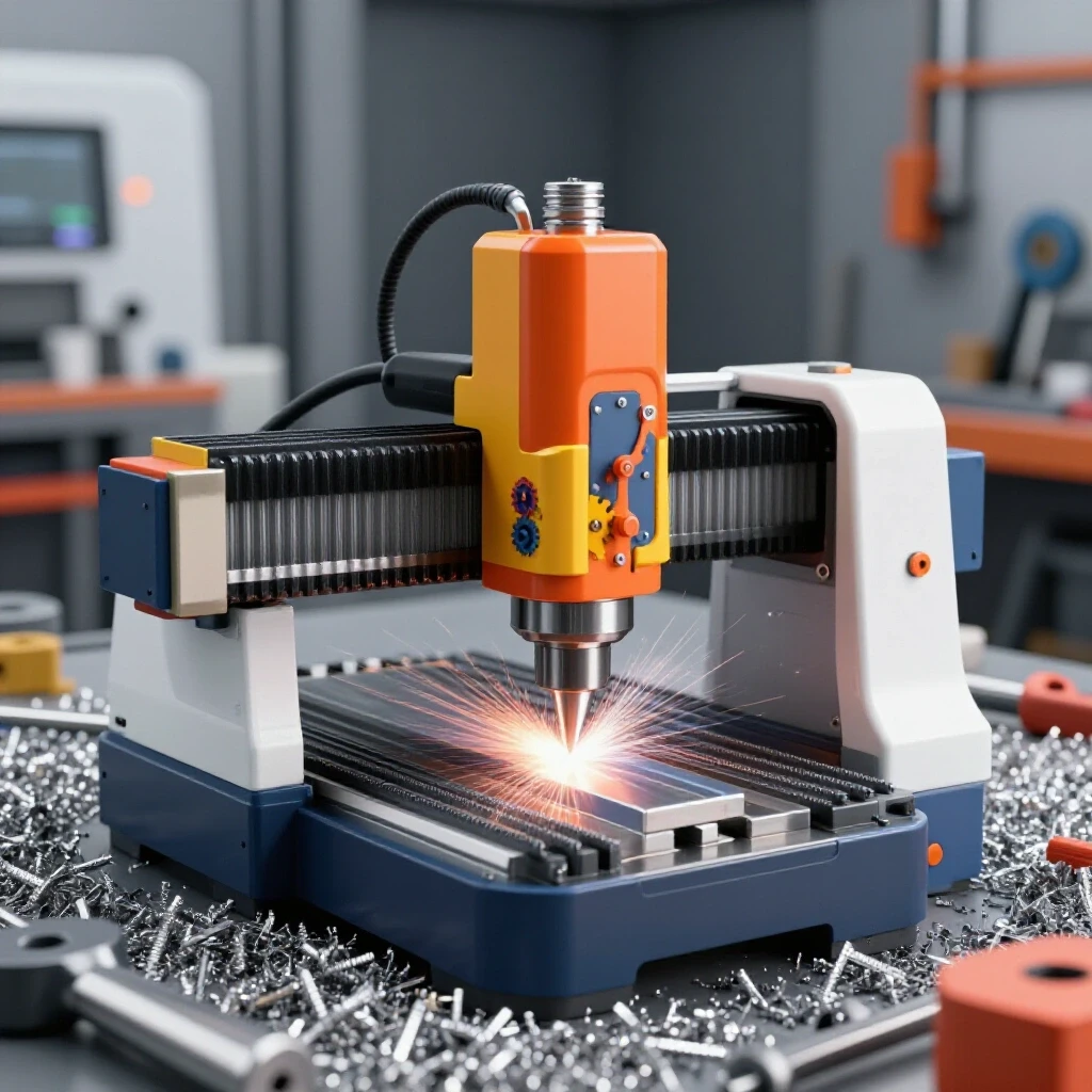
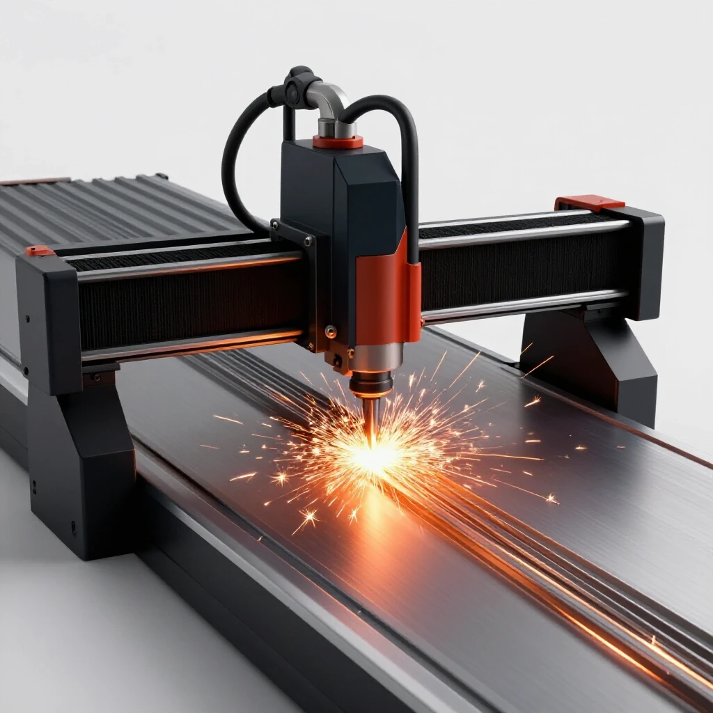
A CNC gantry setup must be perfectly level and square to ensure that the torch stays at a consistent height above the material. Even a 1/8-inch slope across a 10-foot table can cause the Torch Height Control (THC) to work overtime, leading to “diving” or “crashing” into the plate.
When I commission a new table, I use a machinist’s level and a large framing square. I also run a “dry nest” where the machine follows the cut path without the torch on. This allows me to see if the irregular parts are too close to the edge of the sheet or if the gantry will hit a clamp.
- Lead-ins and Lead-outs: These are the small paths the torch takes before and after cutting the actual part shape. For 1/4-inch plate, a 0.15-inch lead-in is usually sufficient to ensure the “pierce hole” doesn’t mar the finished edge.
- Bridge Cutting: For very small parts that might fall through the slats or tip up and hit the gantry, I leave a small “tab” or bridge of metal connecting the part to the main skeleton. This keeps the part stable until the entire sheet is finished.
- Kerf Compensation: The plasma arc has a thickness (the kerf). Your layout must account for this—usually around 0.040 to 0.060 inches—so the finished parts are the correct size.
Workflow Optimization Tips for Scaling Operations
Scaling a fabrication shop requires moving from a “one-off” mindset to a “batch” mindset. Every time you change a tool, swap a sheet, or adjust a setting, you lose money in setup time.
I track my “arc-on” time versus my “handling” time. If it takes 20 minutes to cut a sheet but 40 minutes to load the material and clear the scrap, the bottleneck isn’t the machine—it’s the workflow. Using a magnetic sheet lifter or a jib crane can cut material handling time by 50%, allowing the CNC to stay in motion.
- Standardize Materials: Try to design your products around a few standard thicknesses (e.g., 14ga, 10ga, and 3/16″). This reduces the frequency of changing consumables and air pressure settings.
- The 5S Method: Sort, Set in order, Shine, Standardize, and Sustain. A clean shop is a fast shop. If you spend ten minutes looking for a 1/2-inch wrench, you’ve lost the profit on that hour’s production.
- Digital Documentation: Keep a log of your “cut recipes”—the specific amperage, speed, and air pressure used for different materials. This ensures consistency even if someone else is running the machine.
Actionable Workshop Layout Matrix
To help you evaluate your current setup, use this checklist to identify where your throughput is being choked.
- Material Access: Can you load a full 4×8 sheet without moving any other equipment?
- Power Stability: Does the shop lights flicker when the plasma arc starts? (If yes, check your phase balance).
- Air Quality: Is there visible haze in the shop after 30 minutes of cutting? (If yes, increase CFM or check duct leaks).
- Scrap Rate: Are you throwing away more than 20% of your sheet weight? (If yes, revisit your part rotation and interlocking strategies).
- Safety Zones: Is there a clear 36-inch path to every electrical disconnect and fire extinguisher?
Conclusion
Transitioning your workshop into a high-efficiency space is a marathon, not a sprint. It starts with the physics of the floor and ends with the precision of the cut. By focusing on linear material flow, stable 3-phase power, and the strategic arrangement of parts on every sheet, you can move from hobby-level output to professional-grade manufacturing.
The goal isn’t just to work harder; it’s to create a system where the machine does the heavy lifting and the material is used to its absolute potential. Start by measuring your current travel paths and identifying one bottleneck this week. Whether it’s moving a workbench or installing a more efficient air filter, every small optimization adds up to a more profitable and less stressful shop environment.
FAQ
What is the best way to arrange parts to minimize waste without expensive software? Focus on “interlocking” geometries. If you have triangular parts, face the points toward each other. Rotate irregular shapes by small increments (10-15 degrees) to see if they fit into the “valleys” of adjacent parts. Use a consistent “offset” or gap between parts—usually 1.5 to 2 times the thickness of the material—to prevent the heat from warping the skeleton.
How do I know if I need a rotary phase converter or a VFD? If you are only powering one machine with a 3-phase motor (like a vertical mill), a VFD is cost-effective and provides speed control. If you plan to run a CNC table, a large compressor, and a lathe simultaneously, a rotary phase converter is the better choice as it creates a “power grid” for the whole shop.
Why is air velocity important in dust collection duct design? If the air moves too slowly (low velocity), heavy metal dust will settle inside the pipes, eventually clogging them and creating a fire hazard. You generally want a “transport velocity” of about 3,500 to 4,000 feet per minute (FPM) for metal dust.
Can I use a standard shop floor for a heavy CNC table? Most 4-inch slabs can handle the weight, but the issue is “levelness” and vibration. If the floor is uneven, the table frame will twist. Always use adjustable leveling feet and consider anchoring the machine to the slab once it is perfectly squared.
What is “kerf,” and how does it affect part placement? The kerf is the width of the material removed by the cutting process (the torch flame). If your parts are placed too close together on the layout, the kerf from one cut can “eat into” the adjacent part, ruining its dimensions.
How often should I maintain my air filtration system? In a high-output shop, pre-filters should be checked weekly and main cartridges every 3 to 6 months. A clogged filter increases static pressure, which drops your CFM and allows smoke to linger in the shop.
What is the 3-foot access rule? This is a standard safety and maintenance guideline. Keeping 36 inches of clear space around machinery ensures you can quickly reach emergency stops, perform maintenance, and move around the machine without tripping or being pinned against a wall.
How do I reduce “tip-ups” when cutting small parts? “Tip-ups” occur when a small part falls through the table slats and stands vertically, where the gantry can hit it. To prevent this, use “micro-tabs” (small bridges of uncut metal) to keep the part attached to the skeleton until the job is done.
Is 3-phase power safer than single-phase? It is not necessarily “safer” in terms of shock risk, but it is “healthier” for industrial motors. 3-phase power provides smoother torque, which leads to less mechanical wear and lower operating temperatures for your equipment.
What is the most common mistake in shop layout? The most common mistake is failing to account for material handling. People often place a large machine in a spot where it’s impossible to load a full sheet of steel or remove the finished parts without doing a “multi-point turn” with a cart.
(This article was written by one of our staff writers, Edward Sinclair. Visit our Meet the Team page to learn more about the author and their expertise.)