How to Build a Drill Press Stand to Improve Accuracy (Guide)
I remember the first time I tried to drill a series of critical holes for a custom trailer suspension. I was using a benchtop drill press sitting on a rickety wooden table. Every time the bit bit into the 1/2-inch steel, the whole table flexed. By the time I got to the fourth hole, the alignment was off by nearly an eighth of an inch. That was the day I realized that a precision tool is only as good as the structure supporting it. In my 13 years as a prototype technician, I’ve learned that a rigid, heavy-duty base is the secret to repeatable, perpendicular holes in any custom fabrication project.
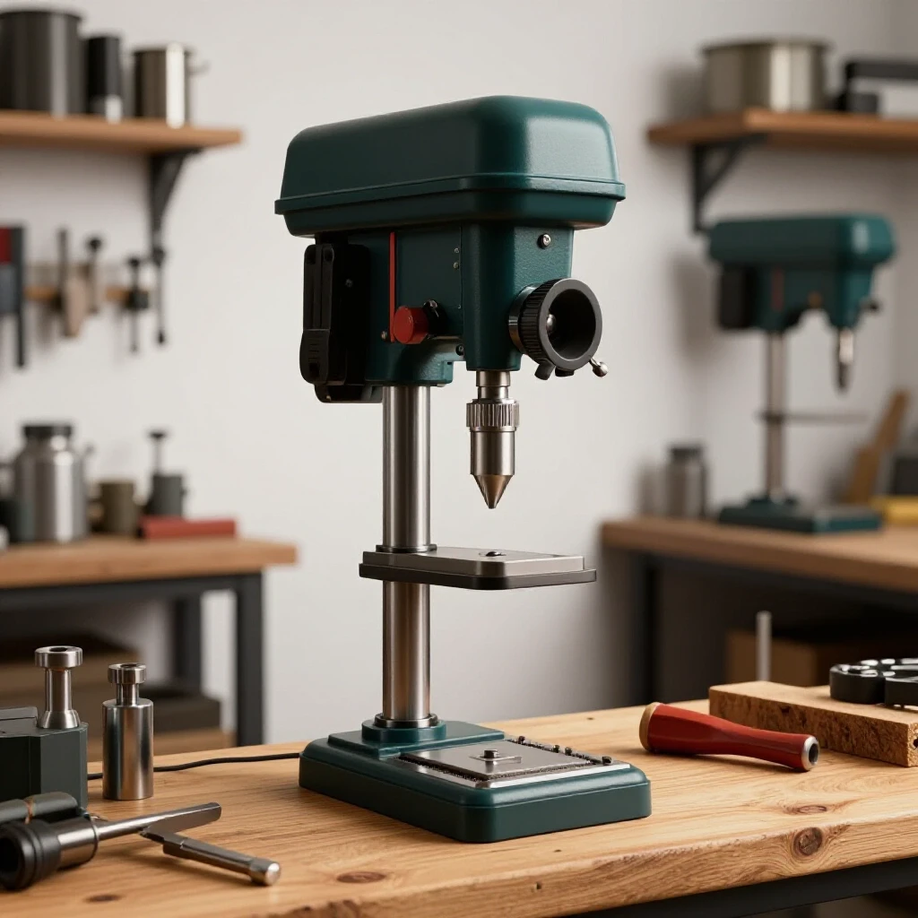
Building a dedicated steel platform for your machinery isn’t just about height; it’s about creating a dead-flat reference surface that resists vibration. When you are working in a home shop, your biggest enemies are movement and heat. If your stand isn’t square, your drill press won’t be square to the floor or your workpieces. This guide walks through the process of designing and fabricating a heavy-duty stand that provides the stability needed for high-tolerance work.
Designing a High-Stability Machine Base
A stable machine base is a structural frame designed to support heavy equipment while minimizing vibration and maintaining a perfectly level work surface. It serves as the foundation for your tool, ensuring that the downward force of the quill doesn’t cause the frame to deflect or “walk” across the shop floor during operation.
When I plan these custom fabrication projects, I start with the footprint. Most benchtop drill presses have a cast iron base with a specific bolt pattern. Your stand needs to be wider than this base to prevent tipping, especially if you’re drilling long pieces of tubing that hang off the side. I typically aim for a footprint at least 20% larger than the tool’s base. For height, I measure from the floor to my elbow; having the drill chuck at elbow height reduces fatigue and improves your line of sight.
Material choice is critical here. I prefer using 2×2-inch angle iron with a 1/4-inch thickness for the main legs and 3/16-inch for the cross braces. This provides enough mass to dampen the motor’s harmonics. If the stand is too light, the vibration will actually cause the drill bit to chatter, which ruins your surface finish and kills your accuracy.
Selecting Materials for Rigidity and Mass
Rigidity refers to a material’s ability to resist deformation under load, while mass helps absorb the energy produced by a machine’s motor. In a workshop environment, combining heavy-gauge steel with a thick top plate creates a “dead” feel that prevents the tool from vibrating out of alignment during heavy use.
I’ve seen guys use thin-wall square tubing because it’s easier to cut, but it doesn’t have the “meat” needed for a serious machine stand. For the top surface, a 3/8-inch or 1/2-inch thick steel plate is ideal. You can drill and tap this plate to bolt the press down directly, rather than using through-bolts with nuts. This makes the assembly much cleaner and more rigid.
| Material Component | Recommended Specification | Why It Matters |
|---|---|---|
| Main Legs | 2″ x 2″ x 1/4″ Angle Iron | Prevents buckling and provides easy clamping surfaces. |
| Cross Bracing | 1.5″ x 1.5″ x 3/16″ Angle | Reduces lateral sway and keeps the frame square. |
| Top Mounting Plate | 3/8″ or 1/2″ Mild Steel Plate | Provides a flat, non-flexing surface for the tool base. |
| Foot Pads | 3″ x 3″ x 1/4″ Steel Tabs | Distributes weight and allows for adjustable leveling feet. |
Mastering the Cut: Kerf Allowances and Layout Precision
Kerf is the width of the material removed by a cutting tool, such as a saw blade or a plasma torch. Accurate layout tips always include accounting for this missing metal so that your final pieces don’t end up shorter than your blueprint specifies, which is a common cause of out-of-square frames.
In my early days, I would mark a line at 30 inches, cut right on the line, and then wonder why my frame was 1/16-inch too narrow. If you are using a dry-cut saw with a 1/8-inch thick blade, that 1/8-inch disappears into dust. To get accurate square cuts, you must mark your line and then cut on the “waste side” of that line.
I use a carbide-tipped dry-cut saw for most of my workshop jigs and fixtures. It produces a much cleaner, cooler cut than an abrasive saw. Abrasive saws generate massive heat, which can actually pre-warp the ends of your steel before you even start welding. Keeping your cuts cool and precise is the first step in controlling the final geometry of the stand.
Metal Kerf Allowances by Cutter Type
Different tools remove different amounts of material, and knowing these values is essential for precise fit-up. If you mix tools during a build without adjusting your measurements, your tolerances will stack up, leading to a lopsided stand that wobbles on the floor.
- Carbide Dry-Cut Saw: 0.090″ – 0.125″ (approx. 1/8″)
- Abrasive Chop Saw: 0.125″ – 0.150″
- Portable Band Saw: 0.025″ – 0.035″
- Plasma Cutter (Handheld): 0.040″ – 0.060″
- Oxy-Fuel Torch: 0.060″ – 0.100″
When I’m aiming for a dimensional tolerance of +/- 1/16th inch, I always use a scribe instead of a soapstone. A soapstone line is nearly 1/8-inch wide itself. A scribe line is thin and precise, allowing you to see exactly where the blade meets the metal.
Creating a Fabrication Jig for Square Assembly
A fabrication jig is a temporary or permanent fixture used to hold workpieces in the correct position during the welding process. It acts as a physical constraint that fights against the natural tendency of metal to move as it is heated and cooled, ensuring the final product remains true.
You don’t need a $5,000 professional fixture table to build a straight stand. I often build a “disposable jig” right on my workbench using scraps of angle iron clamped down to form a 90-degree corner. By nesting your stand’s legs and cross-members into this jig, you force the parts to stay square while you apply your initial tacks.
One trick I’ve used for years is the “3-4-5 rule” for checking squareness on larger frames. If one side is 3 feet, the adjacent side is 4 feet, the diagonal must be exactly 5 feet. For a smaller drill press stand, I use a high-quality machinist square. If you can see light between the square and your steel, it’s not ready to weld.
Fixturing Span and Clamp Placement
The distance between your clamps determines how much the metal can bow between points of contact. For 1/4-inch angle iron, I recommend a clamp spacing metric of no more than 12 inches. If you leave a long span unsupported, the heat from the weld will pull the middle of the bar, creating a “banana” effect.
- Use C-clamps or F-style clamps with at least 300 lbs of clamping force.
- Place clamps within 2 inches of every joint before tacking.
- Always check squareness after tightening the clamps, as the pressure itself can sometimes shift the parts.
- Keep the jig clear of the actual weld zone to avoid welding your project to the fixture.
Tack Welding Strategies to Prevent Structural Shift
A tack weld is a small, temporary weld used to hold components in alignment before the final beads are laid. These small tacks must be strong enough to resist the initial thermal expansion of the metal but small enough to be easily ground out if an adjustment is needed.
I see a lot of builders make the mistake of placing one tiny tack on each corner and then starting their final welds. As soon as that big bead starts cooling, it will rip those tiny tacks apart or pull the frame out of square. For a heavy stand, I use “structural tacks”—these are about 1/2-inch long and placed on opposite sides of the joint.
I follow a specific tacking sequence. First, I tack the outside corners. Then, I re-check squareness. If it’s still good, I tack the inside corners. By “trapping” the joint with tacks on both sides, you create a mechanical lock that resists the angular pull of the final weld.
Tack Spacing and Sizing Benchmarks
The number and size of your tacks should be proportional to the thickness of the material. For 1/4-inch steel, a single 1/8-inch dot isn’t enough. You need enough filler metal to handle the leverage of a 30-inch leg pulling against the joint.
- Tack Size: Aim for a length of 2 to 3 times the thickness of the metal. For 1/4-inch steel, a 1/2-inch to 3/4-inch tack is ideal.
- Tack Count: For a standard angle iron butt joint, use at least four tacks—one on each flat surface and one on each edge.
- Cooling Time: Allow tacks to cool to the touch before removing clamps. This ensures the “freeze” of the metal has fully set the position.
Weld Sequencing for Distortion Control
Weld sequencing is the planned order in which weld beads are applied to a structure to balance the heat input and counteract the forces of contraction. By strategically jumping from one side of a project to the other, you can use the “pull” of a new weld to counteract the “pull” of a previous one.
This is where most custom fabrication projects go wrong. If you start at the top left and weld all the way around to the top right, the cumulative shrinkage will pull the frame into a trapezoid. Metal warping solutions rely on physics: as a weld cools, it shrinks. If all your welds shrink in the same direction, your project will warp in that direction.
I use a “staggered” or “back-step” sequence. I might weld the front-left joint, then move to the back-right joint. Interestingly, by distributing the heat evenly across the entire frame, you prevent any one area from becoming a “heat sink” that pulls the rest of the structure toward it.
| Welding Sequence Type | Description | Best Use Case |
|---|---|---|
| Opposing Corners | Welding diagonally opposite joints in succession. | Squaring up the main base frame. |
| Back-Stepping | Welding in short sections, moving opposite to the direction of travel. | Long seams on the top mounting plate. |
| Intermittent (Stitch) | Leaving gaps between short welds and filling them later. | Attaching cross-braces to legs. |
| Balanced Fillets | Welding one side of a T-joint, then the other immediately. | Preventing a leg from leaning inward. |
Why Weld Shrinkage Warps Square Structures
When steel is heated to its melting point, it expands. When it cools, it contracts. However, because the surrounding metal is cold and rigid, the cooling weld bead can’t just return to its original size; it pulls the surrounding metal with it. This is known as angular distortion.
In my experience, a full-penetration fillet weld on a 90-degree joint can pull the vertical member inward by as much as 1 to 3 degrees. To combat this, I sometimes “preset” my joints. I’ll lean the leg slightly outward (about 1/16-inch over a 12-inch span) before welding. As the weld cools, it pulls the leg right into a perfect 90-degree angle. It takes practice to judge the “pull,” but it’s a pro move for achieving high accuracy.
Managing Metal Warping Solutions During Final Welding
Heat management involves controlling the temperature of the workpiece during the welding process to minimize the zone affected by thermal expansion. Effective management prevents the metal from reaching a point of plastic deformation where it permanently loses its intended shape.
If I’m welding a thick 1/2-inch top plate to the angle iron frame, I’m putting a lot of heat into the project. To keep things flat, I use “heat sinks.” A large block of aluminum or even a heavy copper bar clamped near the weld zone can help pull the heat away from the steel, reducing the total expansion.
Another technique is to avoid “over-welding.” You don’t need a continuous 24-inch bead to hold a drill press stand together. Short, 2-inch “stitch” welds spaced every 4 inches are often stronger because they create less internal stress in the frame. Over-welding is a common rookie mistake that leads to massive distortion and wasted wire.
Heat Control Thresholds and Cooling
Monitoring the temperature of your steel can tell you when to stop and let things cool. If the metal starts glowing dull red several inches away from the weld, you are putting in too much heat too fast.
- Interpass Temperature: For mild steel, try to keep the frame cool enough that you can momentarily touch it (with a gloved hand) about 6 inches from the weld.
- Air Cooling vs. Water Quenching: Never quench a weld with water to cool it down. This can make the steel brittle and cause it to crack. Always let it air cool naturally.
- Clamping Through the Cool: Keep the frame clamped in your jig until it is completely cool to the touch. If you release the clamps while the metal is still “moving” (cooling), it will warp instantly.
Leveling Systems and Final Alignment
A leveling system consists of adjustable feet or shims that allow a machine stand to be perfectly plumb and level on an uneven floor. Final alignment is the process of ensuring the tool’s primary axis—in this case, the drill press spindle—is perpendicular to the stand’s base and the floor.
No garage floor is perfectly flat. If your stand sits on four fixed legs, it will almost certainly wobble. I weld heavy-duty 5/8-inch nuts to the bottom of the leg tabs and use Grade 8 bolts as adjustable feet. By turning the bolts, I can dial in the level of the stand until a precision bubble level shows it is perfect in both directions.
Once the stand is level, I bolt the drill press down. But the job isn’t done. I use a “tramming” technique to check accuracy. I put a bent piece of wire in the chuck and rotate it by hand to see if it maintains the same distance from the table at all points of the circle. If it doesn’t, I use thin brass shims between the drill press base and the stand’s top plate to correct the tilt.
Alignment Checking Steps
- Level the Stand: Use the adjustable feet to get the top plate level within 0.1 degrees.
- Mount the Tool: Secure the drill press to the center of the plate.
- Check the Spindle: Use a dial indicator or a square to check that the spindle is 90 degrees to the stand’s top.
- Shim if Necessary: Place 0.001″ to 0.005″ brass shims under the low side of the drill press base.
- Re-Verify: Tighten all bolts and check the spindle alignment one last time.
Tracking Progress and Lessons Learned
One thing I started doing years ago was keeping a build log. I track the total cost of materials, the time spent on each phase, and any issues I ran into. For a drill press stand, my log usually looks something like this:
- Material Cost: $140 (Steel, fasteners, leveling feet).
- Time Estimate: 8 hours (2 for cutting/prep, 4 for jigging/welding, 2 for finishing/leveling).
- Obstacle: The top plate bowed 1/16-inch during the final weld.
- Solution: Next time, use a more aggressive stitch weld pattern and thicker heat sinks.
This data-driven approach helps me avoid the same mistakes on future workshop jigs and fixtures. It turns every project into a learning experience, which is how you go from a “weekend warrior” to a precision fabricator.
Actionable Benchmarks for the Build
- Dimensional Tolerance: Aim for +/- 1/16th inch on overall height and width.
- Squareness: The diagonals of the frame should be within 1/32-inch of each other.
- Weld Size: Fillet welds should have a leg length equal to the thickness of the thinner material (e.g., 1/4-inch).
- Tack Count: Minimum of 32 tacks for a basic four-legged stand with two levels of bracing.
Building your own machine support is a rite of passage in the fabrication world. It teaches you how to manage heat, how to think in three dimensions, and how to respect the behavior of the metal. When you finally pull a lever and see a drill bit go perfectly straight through a piece of 1-inch plate, you’ll know the effort was worth it.
FAQ
Why should I use angle iron instead of square tubing for a machine stand? Angle iron is often preferred for these custom fabrication projects because it provides easy access to both sides of the metal for clamping. It also doesn’t have the internal radius issues that some square tubing has, making it easier to seat a flat plate on top. Additionally, angle iron is easier to clean and paint, as there are no “closed” sections where moisture can trap and cause rust.
How do I stop the top plate from warping when I weld it to the frame? The best way to prevent warping on a large top plate is to use a stitch welding sequence. Instead of one long bead, lay down 1-inch welds every 4 to 6 inches. Always work from the center of the plate outward toward the corners. This allows the heat to dissipate more evenly and prevents the plate from “oil-canning” or bowing in the middle.
What is the best way to ensure the stand is perfectly level on a cracked garage floor? Standard fixed legs will always wobble on uneven concrete. The most effective solution is to weld a 1/2-inch or 5/8-inch nut to the bottom of each leg. You can then use a matching bolt with a locking nut as an adjustable foot. For a professional touch, use vibration-damping rubber pads under the bolt heads to keep the machine from “walking.”
How much should I account for “weld pull” when squaring the legs? Weld pull, or angular distortion, typically moves a part 1 to 2 degrees toward the side being welded. If you are welding the inside of a corner, the leg will pull inward. To counteract this, you can either “over-square” the leg by about 1/16-inch outward or use very strong fixturing jigs that hold the leg at exactly 90 degrees until the weld is completely cold.
Can I build a stand without a professional welding table? Absolutely. You can use any flat surface, including a concrete floor, as long as you verify it’s level. You can create workshop jigs by clamping straight pieces of scrap steel to your workpiece to act as guides. The key is constant measurement with a high-quality square and using the “3-4-5 rule” for larger frames.
What thickness of steel is “overkill” for a drill press stand? While you want mass, anything over 1/2-inch plate for the top or 3/8-inch for the legs becomes difficult to move and expensive. For a standard 12-inch to 15-inch benchtop drill press, 1/4-inch angle iron and a 3/8-inch top plate provide a perfect balance of extreme rigidity and manageable weight.
Should I bolt the stand to the floor? For a drill press, it isn’t usually necessary to bolt the stand to the floor unless the machine is exceptionally top-heavy or you are drilling very large, unbalanced parts. If you do choose to bolt it down, use wedge anchors and ensure the stand is leveled with shims before tightening the anchors to avoid stressing the frame.
How do I calculate the kerf for my specific saw? The easiest way is to take a scrap piece of metal, measure it exactly (e.g., 5 inches), make a cut, and then measure the two remaining pieces. If the two pieces add up to 4-7/8 inches, your kerf is exactly 1/8-inch. Always use this specific measurement when planning your cutting layout tips.
Is MIG or TIG better for building shop fixtures? MIG is generally better for building stands and frames because it is faster and provides excellent penetration on thicker 1/4-inch steel. TIG is great for precision, but the high heat input over a longer period can actually lead to more warping on a large frame compared to the quick, “cooler” passes of a MIG welder.
What is the most common mistake when building a custom stand? The most common mistake is rushing the cooling process. Builders often get the frame tacked and welded, then immediately unclamp it to see their work. Because the metal is still shrinking as it cools, the frame will pull out of square the moment the clamps are released. Patience during the cooling phase is the key to accuracy.
(This article was written by one of our staff writers, Robert Kline. Visit our Meet the Team page to learn more about the author and their expertise.)