How to Check and Square Large Welded Metal Frames (Tutorial)
In my fourteen years navigating the grit and precision of industrial fabrication, I have learned that the most dangerous moment for any structural project isn’t during the welding itself—it is the moment you lift the clamps. I have stood over twenty-foot steel base frames that looked perfect while tacked to a heavy table, only to watch them “walk” and twist as the internal stresses of the cooling metal took hold. When a frame loses its geometry, it isn’t just an aesthetic problem; it creates uneven load paths that can lead to premature structural fatigue or catastrophic failure under weight.
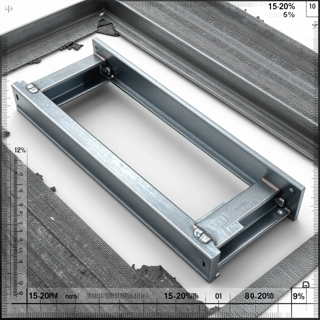
The transition from a collection of steel members to a unified structural frame involves massive thermal energy. As the heat-affected zone (HAZ) cools, the metal contracts, exerting thousands of pounds of pull on your joints. If you are building a heavy equipment stand or a structural mezzanine, you cannot simply assume the frame remained true because your initial layout was accurate. Verification is a rigorous, post-weld process of measuring, analyzing, and occasionally correcting the physical reality of the metal in front of you.
The Mechanics of Post-Weld Distortion and Structural Alignment
Structural alignment refers to the precise positioning of metal components relative to a defined geometric plane and 90-degree axes. It ensures that the finished assembly distributes weight evenly across all support points and fits into its intended workspace without mechanical interference.
When we talk about checking a large assembly, we are looking for three specific types of error: angular deviation, dimensional drift, and planar twist. Angular deviation occurs when a corner that should be 90 degrees pulls into an acute or obtuse angle. Dimensional drift is the change in the overall length or width of the frame due to cumulative shrinkage. Planar twist, often called “winding” in the shop, is when the frame is no longer flat, resulting in one corner lifting off the ground while the others remain seated.
In my experience inspecting heavy frames for the mining industry, even a 1/8-inch deviation over a ten-foot span can cause significant issues during the installation of precision machinery. The following table outlines the common tolerances I look for based on the intended use of the structure.
| Application Type | Max Angular Deviation | Max Planar Twist (per 10ft) | Diagonal Difference |
|---|---|---|---|
| General Utility Framing | +/- 0.5 degrees | 1/8 inch | < 1/4 inch |
| Structural Load Bearing | +/- 0.2 degrees | 1/16 inch | < 1/8 inch |
| Precision Machine Bases | +/- 0.05 degrees | 0.020 inch | < 1/16 inch |
Essential Tools for Large Scale Geometric Verification
Verification tools are the precision instruments used to measure the accuracy of a frame after the welding process is complete. These tools must be checked for their own calibration to ensure that the data they provide is reliable and repeatable.
For large-scale work, a standard six-inch combination square is insufficient. You need tools that can bridge the span of the material to provide a true reading. I rely on a “master square,” which is a large, high-precision steel square, usually 24 by 36 inches. Additionally, a calibrated 50-foot steel tape measure is vital. Note that I specify “steel”—fiberglass tapes can stretch under tension, leading to inaccurate diagonal readings on frames over ten feet long.
- Long-Reach Straightedges: These are used to check the “bow” or “crown” in a long rail. A six-foot or eight-foot aluminum straightedge is a standard requirement.
- Precision Plumb Bobs and String Lines: For verifying verticality and straightness over very long distances where a physical straightedge cannot reach.
- Digital Inclinometers: These tools measure the angle of a surface relative to the earth’s gravity, providing a digital readout of “level” and “plumb” to within a tenth of a degree.
- Trammel Points: These are adjustable pointers that clamp onto a long bar, allowing you to compare distances between two points with higher precision than a tape measure.
Validating Right Angles and Corner Squareness
Corner squareness is the state where two intersecting members form a perfect 90-degree angle. This is the foundation of structural integrity, as it ensures that vertical loads are transferred directly through the center of the supporting members.
The most reliable method for checking squareness on a large frame is the 3-4-5 triangulation method, a practical application of the Pythagorean theorem. By measuring three feet down one rail and four feet down the intersecting rail, the diagonal distance between those two points must be exactly five feet. On larger frames, I scale this up to 6-8-10 or 9-12-15 to increase the accuracy of the reading. If the diagonal is even 1/16th of an inch off, the angle is not a true 90 degrees.
- Mark the Reference Points: Use a fine-point scribe or a silver streak pencil to mark your distances from the exact inside corner of the joint.
- Measure the Hypotenuse: Pull your tape measure tight between the two marks. Any slack in the tape will result in a false “short” reading.
- Cross-Check Diagonals: For any rectangular frame, the two corner-to-corner diagonals must be identical. If one is longer than the other, the frame has shifted into a parallelogram.
- Verify Inside and Outside: Use a large square to check the joint itself, ensuring that the vertical member hasn’t “leaned” inward or outward during the cooling process.
Assessing Planar Flatness and Surface Twist
Planar flatness is the condition where all surfaces of a frame exist on a single, two-dimensional plane. Surface twist, or “propeller” warp, occurs when the corners of the frame are not co-planar, causing the structure to rock or sit unevenly.
Identifying twist in a large frame can be difficult with the naked eye. I use a technique called “sighting the winding sticks.” By placing two perfectly straight, identical bars across opposite ends of the frame and looking across the top of them, any deviation in height becomes immediately apparent. If the bars are not parallel to each other, the frame is twisted. This is a classic millwright’s trick that remains the most effective way to spot planar errors in a workshop environment.
- The String Test: Stretch two high-tension strings diagonally from corner to corner. They should lightly touch where they cross in the middle. If there is a gap, or if one string pushes down on the other, the frame is twisted.
- The Level Comparison: Place a high-precision spirit level or digital inclinometer on the four outer rails. If the two parallel rails show different slopes, a twist is present.
- Feeler Gauge Check: Place the frame on a known flat surface, such as a precision welding table or a leveled concrete floor. Try to slide a feeler gauge under the corners. Any gap indicates a lack of flatness.
Techniques for Correcting Dimensional Deviations
Dimensional correction is the process of physically manipulating a welded assembly to return it to its specified geometric tolerances. This is necessary when the cooling welds have pulled the frame out of square or out of plane.
In my years on the shop floor, I have learned that metal is surprisingly elastic, but it has a “memory.” If a frame is out of square, you can often use mechanical force—such as heavy-duty F-clamps, bottle jacks, or come-alongs—to pull it back into position. However, simply pulling it isn’t enough; you often have to “over-bend” the metal slightly past the 90-degree mark so that when the tension is released, it springs back to the correct position.
- Mechanical Cold Straightening: This involves using jacks or presses to physically move the metal. It is best for minor angular corrections.
- Thermal Stress Relief: Sometimes, the only way to fix a twist is to apply localized heat to the side of the member that needs to contract. This is a high-skill technique where you “shrink” the metal to pull the frame into alignment.
- Strategic Shim Usage: If a frame is slightly out of plane and cannot be moved, the final mounting points may need to be shimmed or ground down to ensure the load is distributed evenly.
- Vibratory Stress Relief: In industrial settings, we sometimes use specialized equipment to vibrate the frame, which allows the internal weld stresses to “settle” and reduces the likelihood of future movement.
Troubleshooting Common Structural Misalignments
Structural troubleshooting is the diagnostic process of identifying why a frame moved and determining the best path for correction. It requires an understanding of how heat travels through specific joint geometries.
I once worked on a large rectangular skid for a backup generator. After welding, the center of the 15-foot side rails had bowed inward by nearly a quarter of an inch. This happened because all the welding was done on the inside of the frame first, which pulled the metal toward the center. We had to use a hydraulic spreader to push the rails back out while we performed “counter-welding” on the outside to balance the stresses.
| Symptom | Probable Cause | Verification Method |
|---|---|---|
| Corner angle > 90° | Too much heat on the outside of the joint | 3-4-5 Triangulation |
| Rail “Bowing” (Crowning) | Continuous weld beads on one side of a long member | String line or 8ft Straightedge |
| One corner “Floating” | Uneven cooling or welding sequence | Winding sticks or Feeler gauges |
| Overall length is short | Cumulative shrinkage from multiple cross-members | Calibrated steel tape measure |
Structural Verification Checklist for Final Inspection
A verification checklist is a formal document used to record the final measurements of a project. This ensures that every critical dimension has been checked and that the frame meets the safety and functional requirements of the design.
Before I sign off on any large assembly, I go through a systematic “walk-around.” This isn’t just about looking at the welds; it is about confirming the geometry in a logical sequence. I start with the overall dimensions, move to the squareness of the corners, and finish with the planar flatness. By following a set order, I ensure that I don’t miss a subtle twist that could cause the frame to fail once it is loaded with several thousand pounds of equipment.
- Step 1: Length and Width Verification. Measure all outer dimensions and compare them to the original prints.
- Step 2: Diagonal Cross-Check. Record both corner-to-corner measurements. They must be within the allowed tolerance (e.g., 1/8″).
- Step 3: Vertical Plumb Check. If the frame has uprights, use a level or plumb bob to ensure they are at 90 degrees to the base.
- Step 4: Planar Twist Test. Use winding sticks or a string test to confirm all four corners sit on the same plane.
- Step 5: Surface Flatness. Run a straightedge along the mounting surfaces to check for “high spots” caused by weld reinforcement or heat distortion.
- Step 6: Center-to-Center Holes. If the frame has pre-drilled mounting holes, verify the distance between them to ensure they haven’t shifted during welding.
Conclusion: The Value of Precision in Heavy Fabrication
Building a large metal frame is a balancing act between the raw power of heat and the precise requirements of geometry. I have found that the most successful fabricators are the ones who are the most skeptical of their own work. They don’t assume a frame is square; they prove it with a tape measure and a straightedge.
Taking the time to verify your work post-weld prevents the “cascading error” effect, where a small mistake in the base frame leads to massive alignment issues as you add more components. Whether you are building a trailer, a shop crane, or a heavy-duty workbench, the integrity of your project relies on the accuracy of its bones. By mastering these verification techniques, you move from a hobbyist who “hopes” it fits to a craftsman who knows it is right.
Frequently Asked Questions
How much deviation is acceptable in a large steel frame? For most structural workshop projects, a deviation of 1/8 inch over ten feet is considered the standard tolerance. If you are building a base for a precision machine like a lathe or a CNC mill, that tolerance drops significantly, often requiring less than 0.020 inches of deviation to prevent the machine from twisting.
Why did my frame pull out of square even though I used heavy clamps? Clamps can hold a frame in place during the welding process, but they cannot stop the metal from contracting as it cools. When you release the clamps, the internal stresses stored in the welds will pull the metal. This is why checking for squareness after the frame has cooled is the only way to know the true dimensions.
What is the “3-4-5 method” and why is it better than a square? The 3-4-5 method uses the Pythagorean theorem (A² + B² = C²) to create a large-scale right triangle. A standard carpenter’s square is only 24 inches long; any tiny error in the square is magnified over a ten-foot span. By using a 3-4-5 foot (or 6-8-10 foot) triangle, you are checking the angle over a much larger distance, which significantly increases your accuracy.
How do I fix a “propeller twist” in a rectangular frame? A twist is often fixed by “heat shrinking” or mechanical force. You can clamp three corners of the frame down to a flat table and use a heavy jack to lift the fourth corner slightly past the “flat” point, then release it. If the twist is severe, you may need to apply heat to the high side of the diagonal members to pull the frame back into plane.
Does the thickness of the metal affect how much it will warp? Yes. Thinner materials (like 1/8″ wall tubing) heat up faster and distort more easily than thick-walled structural steel (like 1/2″ plate). However, thick sections also exert much more force when they contract, which can actually bend other parts of the frame if the welding sequence isn’t managed correctly.
Can I use a laser level to check for squareness? Laser levels are excellent for checking if a frame is level or plumb, but they can be tricky for checking squareness unless you have a “squaring laser” that projects two beams at a perfect 90-degree angle. Even then, you must verify the laser’s accuracy over the distance of your frame.
What are “winding sticks” and how do they work? Winding sticks are two identical, perfectly straight bars. You place one at each end of your frame and sight across the top of them with your eye. If the sticks look parallel, your frame is flat. If the sticks appear to cross or “wind,” one corner of your frame is higher than the others.
How often should I check my tape measure for accuracy? In a professional shop, we check tapes every few months. Look for a bent “hook” at the end. If the hook is loose (which it should be to account for its own thickness), ensure it isn’t bent inward or outward, as this will throw off your “inside” and “outside” measurements by 1/16th of an inch or more.
Should I check for square while the metal is still hot? No. Metal expands when hot and contracts as it cools. If you measure a frame while it is still 400 degrees Fahrenheit, your measurements will be slightly larger than they will be when the frame reaches room temperature. Always wait for the metal to be cool enough to touch before performing final verification.
What is the best way to record these measurements for a client or for safety records? Create a simple “as-built” sketch of the frame. Mark each corner with its measured angle or diagonal distance and note the planar flatness at each support point. Keeping this in a project log provides a paper trail that proves the structure was built to the required specifications.
(This article was written by one of our staff writers, James Harlan. Visit our Meet the Team page to learn more about the author and their expertise.)