How to Build a Metal Wall Holder for Angle Grinders (Guide)
I have spent over a decade in fabrication shops, and if there is one thing I have learned, it is that steel has a mind of its own. You can spend two hours measuring, scribing, and double-checking your marks, only to watch your project pull a quarter-inch out of square the moment you lay down a heavy bead of weld. It is a frustrating reality for every builder, whether you are working on a custom truck chassis or a simple storage solution for your shop. In my early days, I assumed that more clamps were the only answer to warping. I was wrong. Success in the shop comes down to understanding how heat moves through metal and how to plan your cuts to account for the physical realities of the fabrication process.
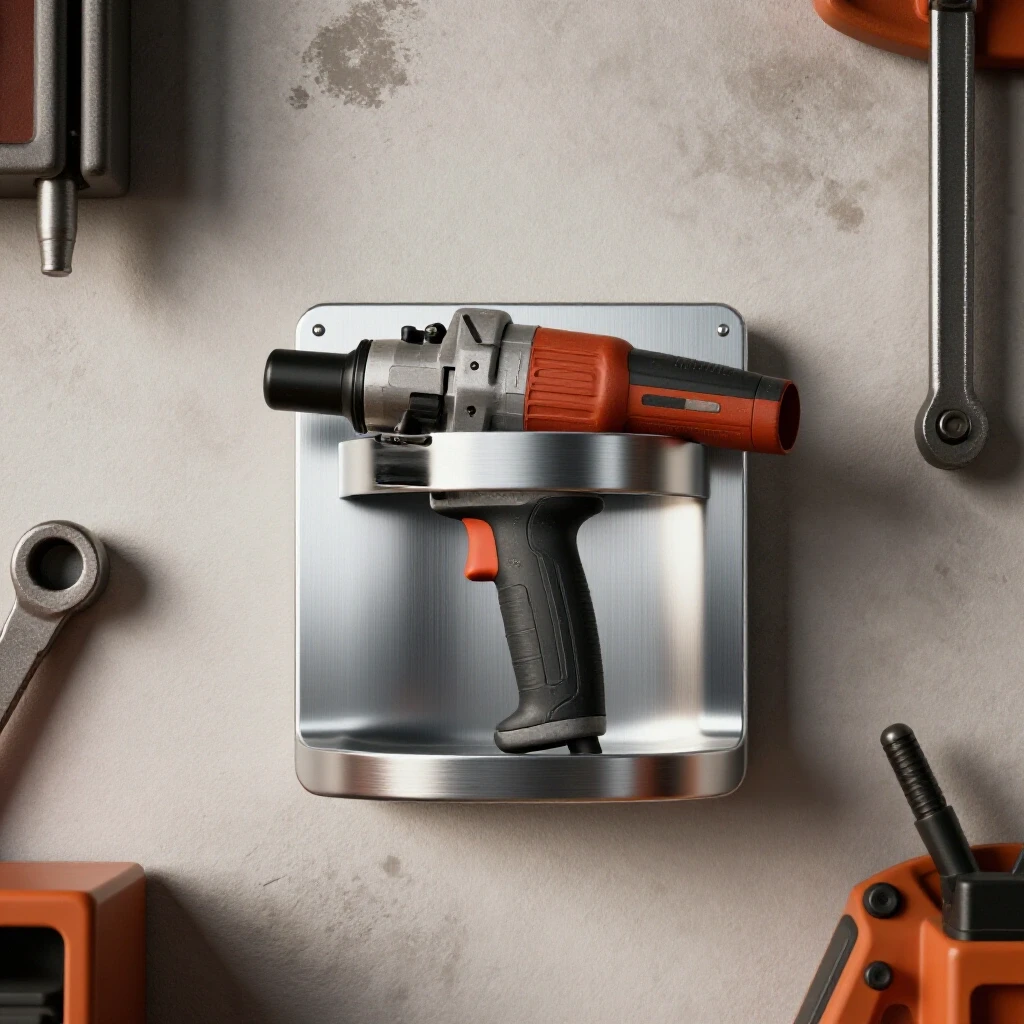
When I set out to build a heavy-duty rack for my shop’s 4.5-inch grinders, I approached it with the same rigor I use for structural fixtures. A simple wall-mounted bracket might seem like a minor project, but it is the perfect playground to practice layout precision and heat control. If you can keep a multi-slot tool holder perfectly flat and square, you can build a utility trailer or a workbench with confidence. This guide focuses on the technical side of building a durable, steel storage fixture while managing the common pitfalls of metal movement and layout errors.
Mastering the Blueprint and Material Selection
Planning your material layout involves creating a precise roadmap for every cut and hole before the first spark flies. This stage accounts for blade thickness, material overlap, and the physical space required for the tool to hang safely. Proper planning prevents wasted steel and ensures the final rack fits your shop’s wall space.
Before I touch a saw, I visualize the final assembly. For a multi-tool rack, I typically use 1/8-inch or 3/16-inch thick flat bar for the main body and 1-inch angle iron for the mounting rails. The weight of three or four grinders, plus the force of pulling them in and out of the slots, requires a rigid structure. If you go too thin, the slots will eventually sag under the weight.
I start by calculating my “cut list.” This is not just a list of lengths; it is a calculation of how much material I need, including the “kerf.” The kerf is the width of the material removed by the cutting blade. If you are using a standard chop saw with an abrasive blade, you might lose 1/8-inch of steel with every cut. If you ignore this over five or six cuts, your final piece will be nearly an inch short.
- Flat Bar (Main Plate): 3/16″ x 4″ hot-rolled steel.
- Angle Iron (Support): 1″ x 1″ x 1/8″ for the wall-side reinforcement.
- Dimensional Tolerance: My goal for this build is +/- 1/16-inch across the total length.
Understanding Kerf and Layout Allowances
When I mark my steel, I use a carbide scriber rather than a soapstone or a thick marker. A marker line can be 1/16-inch wide on its own, which introduces immediate error. By using a fine scribe line and cutting on the “waste side” of the line, I maintain the dimensions specified in my plan.
| Cutter Type | Average Kerf Width | Accuracy Level |
|---|---|---|
| Abrasive Chop Saw | 1/8″ to 5/32″ | Moderate (requires cleanup) |
| Cold Cut Saw | 3/32″ | High (clean edges) |
| Plasma Cutter | 1/16″ to 1/8″ | Variable (depends on tip) |
| Angle Grinder (Thin Cut) | 3/64″ to 1/16″ | High (manual control) |
Building Workshop Jigs for Alignment
A fabrication jig is a temporary structure or setup used to hold parts in the exact position required for assembly. Jigs eliminate the need to hold pieces by hand and ensure that every angle remains consistent throughout the welding process. They are the secret to building professional-grade shop fixtures.
For this storage project, I don’t just hold the metal pieces together and hope for the best. I use my welding table as a base and set up “stops” or “fixtures.” A fixture can be as simple as two pieces of heavy scrap metal clamped to the table to form a perfect 90-degree corner. When I slide my flat bar and angle iron into this corner, I know they are square before I ever strike an arc.
In my experience, “eyeballing” a project is the fastest way to create a trapezoid. If you are building a holder with four identical slots for grinders, you should cut a “spacer block” out of scrap wood or metal. By placing this block between your metal tabs as you weld, you ensure every slot is the exact same width. This is a common practice in chassis building that translates perfectly to shop organization projects.
- Clamp Spacing: Place a clamp every 4 to 6 inches to prevent the metal from “walking” during tacking.
- Squaring: Use a machinist’s square rather than a standard carpenter’s square for higher precision on small parts.
Controlling Metal Warping with Strategic Tacking
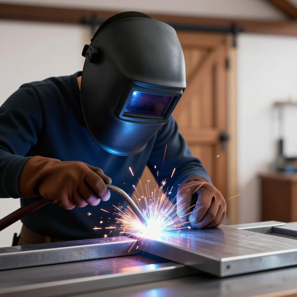
Tack welding involves placing small, temporary welds at key points to hold an assembly together before the final beads are applied. These tacks must be strong enough to resist the cooling forces of the metal but small enough to be easily removed or welded over. Proper tacking is the primary defense against distortion.
When you heat steel with a welder, it expands. As it cools, it contracts. This contraction, or “weld shrinkage,” exerts a massive amount of force on your joints. If you weld one side of a bracket completely before starting the other, the cooling metal will pull the bracket toward the weld. I have seen 1/4-inch plate bend like a piece of cardboard because of poor sequencing.
For a wall rack, I start with “opposing tacks.” If I am joining a vertical support to a horizontal plate, I place a small tack on the front, then immediately place one on the back. This balances the pull. For a 4-inch wide joint, I use at least three tacks: one at each end and one in the center.
Tack Weld Sizing and Placement
A good tack should be about 1/2-inch long for 3/16-inch material. It needs to penetrate both pieces of metal. If the tack is too cold, it will “pop” as the main weld cools and pulls on it. I always check for squareness after every two tacks. If the metal has moved, I can usually tap it back into place with a dead-blow hammer before the tacks get too cold.
- Clean the Joint: Remove all mill scale with a flap disc within one inch of the weld zone.
- Position Parts: Use your jig or clamps to hold the pieces at the 1/16-inch tolerance mark.
- Tack Sequence: Start at the center and move outward to the corners.
- Verify Alignment: Use a square to check both the horizontal and vertical planes.
Executing the Weld Sequence to Manage Heat
Weld sequencing is the deliberate order in which you apply final welds to a project to balance thermal expansion and contraction. By jumping between different areas of the assembly, you distribute heat more evenly and prevent one side from pulling harder than the other. This technique is vital for maintaining straightness.
Once the rack is tacked and verified, the temptation is to run one long, beautiful bead from end to end. Resist that urge. Long, continuous beads put an enormous amount of heat into the steel, which is the leading cause of warping. Instead, I use “back-stepping” or “stitching.”
I might weld two inches on the far left slot, then move to the far right slot. By the time I come back to the middle, the first weld has started to cool. This “skipping” method keeps the overall temperature of the workpiece lower. In my years building utility trailers, I learned that the slower you go with the sequence, the straighter the final product will be.
| Welding Strategy | Effect on Distortion | Recommended Use |
|---|---|---|
| Continuous Bead | High Distortion | Heavy structural beams only |
| Stitched Welds | Low Distortion | Thin plate and sheet metal |
| Back-stepping | Controlled Pull | Long joints in flat bar |
| Opposing Beads | Balanced Pull | T-joints and corner joints |
The Physics of Angular Shrinkage
When you weld a “T-joint” (like the supports on your grinder rack), the weld bead is shaped like a triangle. The wider part of the triangle is at the surface. Because there is more metal at the top of the weld than at the root, the top shrinks more as it cools. This creates “angular distortion,” pulling the upright piece toward the weld. To combat this, I sometimes “preset” the joint by leaning the piece 1 or 2 degrees away from the weld side, knowing it will pull back to 90 degrees as it cools.
Accurate Drilling and Mounting Preparation
Preparing a metal fixture for wall mounting requires precise hole placement and consideration of the load-bearing surface. This step involves calculating the center-to-center distance of wall studs and ensuring the mounting holes are sized correctly for heavy-duty fasteners. Accuracy here ensures the rack remains level and secure under weight.
Most garage walls use studs spaced 16 inches apart. If your grinder rack is 24 inches long, you need to ensure your mounting holes align with those studs. I never rely on drywall anchors for metal tool racks; the vibration and weight will eventually pull them out. I plan my mounting holes to be 16 inches apart, centered on the plate.
I use a center punch to mark the hole locations. Without a punch, the drill bit will “walk” across the steel, and your holes will be misaligned. For a 5/16-inch lag bolt, I drill a 3/8-inch hole. That extra 1/16-inch gives me a “fudge factor” to level the rack on the wall even if my drilling or the wall studs are slightly off.
- Pilot Holes: Always drill a 1/8-inch pilot hole before using a larger bit. It reduces heat and increases accuracy.
- Drill Speed: For steel, use a slower RPM with plenty of cutting fluid to prevent dulling the bit.
Finishing and Post-Weld Corrections
The finishing process involves removing sharp edges, cleaning up weld spatter, and applying a protective coating to prevent rust. It also includes the final inspection and any necessary mechanical straightening to correct minor heat-induced bows. A professional finish protects the metal and the tools it holds.
Even with a perfect sequence, you might find a slight bow in the main plate. This is where “mechanical correction” comes in. If the plate has a slight curve, I place it over two blocks of wood and apply pressure in the center with a large C-clamp or a hydraulic press. Steel is elastic to a point; you can often “massage” it back to straightness if you are careful.
For the edges, I use a 60-grit flap disc on an angle grinder. I round off every corner. In a busy shop, a sharp 90-degree corner on a metal rack is a safety hazard waiting to happen. Once the metal is smooth, I wipe it down with acetone to remove all oils before applying a coat of self-etching primer and a durable enamel paint.
- Deburr: Run a file or flap disc along every cut edge.
- Clean: Use a wire brush to remove silica deposits from the welds.
- Degrease: Acetone or brake cleaner is essential for paint adhesion.
- Paint: Apply two thin coats rather than one thick, runny coat.
Summary Checklist for a Successful Build
I have found that keeping a physical checklist on the workbench prevents me from skipping the small steps that lead to big errors. Here is the framework I use for every custom fabrication project:
- Verify Cut List: Account for 1/8″ kerf on all abrasive cuts.
- Scribe Layout: Use a carbide tip for 1/64″ precision lines.
- Setup Fixture: Clamp “stops” to the table to ensure a square base.
- Tack Sequence: Apply opposing tacks at 2-inch intervals.
- Check Square: Verify dimensions before final welding.
- Weld Sequence: Skip-weld to distribute heat (max 2″ beads).
- Cooling: Allow the piece to air-cool; never quench in water (causes brittleness).
- Mounting Holes: Center-punch and drill 16″ on center for studs.
- Finishing: Flap-disc all edges to a 1/16″ radius for safety.
Frequently Asked Questions
Why does my metal rack bow upward after I weld the slots?
This is caused by longitudinal shrinkage. As the weld beads along the slots cool, they contract and pull the ends of the flat bar toward the center. To minimize this, use the smallest weld bead necessary for the load and use a staggered welding sequence to balance the heat.
Can I use a MIG welder for this project, or is TIG better?
MIG is perfectly fine and often preferred for shop fixtures because it is fast. However, MIG puts more heat into the part than TIG in many cases. If you use MIG, be extra diligent about your skip-welding sequence to manage the higher heat input.
What is the best way to ensure the slots are wide enough for the grinders?
Measure the neck of your specific grinders (the area between the gear housing and the guard). Usually, a 1.5-inch slot is sufficient. I recommend cutting a “test slot” in a piece of scrap and checking the fit before cutting your main workpiece.
How do I prevent the drill bit from overheating when making mounting holes?
Use a slow drill speed (around 300-500 RPM for 3/8″ holes) and apply constant pressure. Use a dedicated cutting oil or even WD-40 to lubricate the bit. If the bit starts to smoke, you are going too fast or not using enough pressure.
Is hot-rolled or cold-rolled steel better for this?
Hot-rolled steel is cheaper and perfectly adequate for shop fixtures. However, it has “mill scale” (a dark grey coating) that must be ground off before welding. Cold-rolled steel is cleaner and more dimensionally accurate but costs significantly more.
How many tacks are enough for a 12-inch bracket?
For a 12-inch joint, I would use at least four tacks: one at each end and two spaced evenly in the middle. This ensures the metal cannot “fan out” as you begin your final welding passes.
Should I weld both sides of the support angle iron?
For a tool rack, welding one side is usually structurally sufficient, but welding both sides prevents moisture from getting trapped between the two pieces of metal, which causes rust. If you weld both sides, be sure to alternate sides to balance the pull.
What size lag bolts should I use for mounting?
I recommend 5/16-inch diameter lag bolts that are at least 2.5 inches long. This ensures you get at least 1.5 to 2 inches of thread engagement into the wooden wall stud after passing through the metal and the drywall.
How do I fix a piece that has already warped?
You can use “flame straightening” or mechanical force. For a small rack, a large bench vise or a C-clamp and two blocks of wood are usually enough to pull a minor bow out of 3/16-inch flat bar.
Why did my weld crack when I finished the project?
Cracks usually happen because the weld was too small for the stress of the shrinkage or because the metal was quenched in water. Always let your projects air-cool naturally to allow the internal stresses to normalize.
Building shop storage is more than just an organization task; it is an exercise in precision. By focusing on your layout, respecting the physics of heat, and following a disciplined welding sequence, you create a tool that is both functional and a testament to your skills as a fabricator. Every time you reach for a grinder, you will see a straight, square, and solid piece of work that was built to last.
(This article was written by one of our staff writers, Robert Kline. Visit our Meet the Team page to learn more about the author and their expertise.)