How to Build a Mini Press Brake for a Shop Press (DIY Plan)
I still remember the first time I tried to bend a set of mounting tabs for a custom utility trailer. I was using a heavy-duty vise and a three-pound sledgehammer, hoping for a clean 90-degree angle. By the third tab, my arms were tired, the metal looked like it had been chewed by a lawnmower, and not a single piece was square. That frustration is what eventually pushed me to build my own compact bending attachment for my hydraulic shop press.
In my thirteen years as a prototype technician, I’ve learned that the difference between a “garage project” and a professional-grade build usually comes down to the fixtures you use. When you are working on custom fabrication projects, you need repeatability. You need to know that if you cut four pieces of 1/8-inch plate, they will all come out with the same bend radius and the same angle.
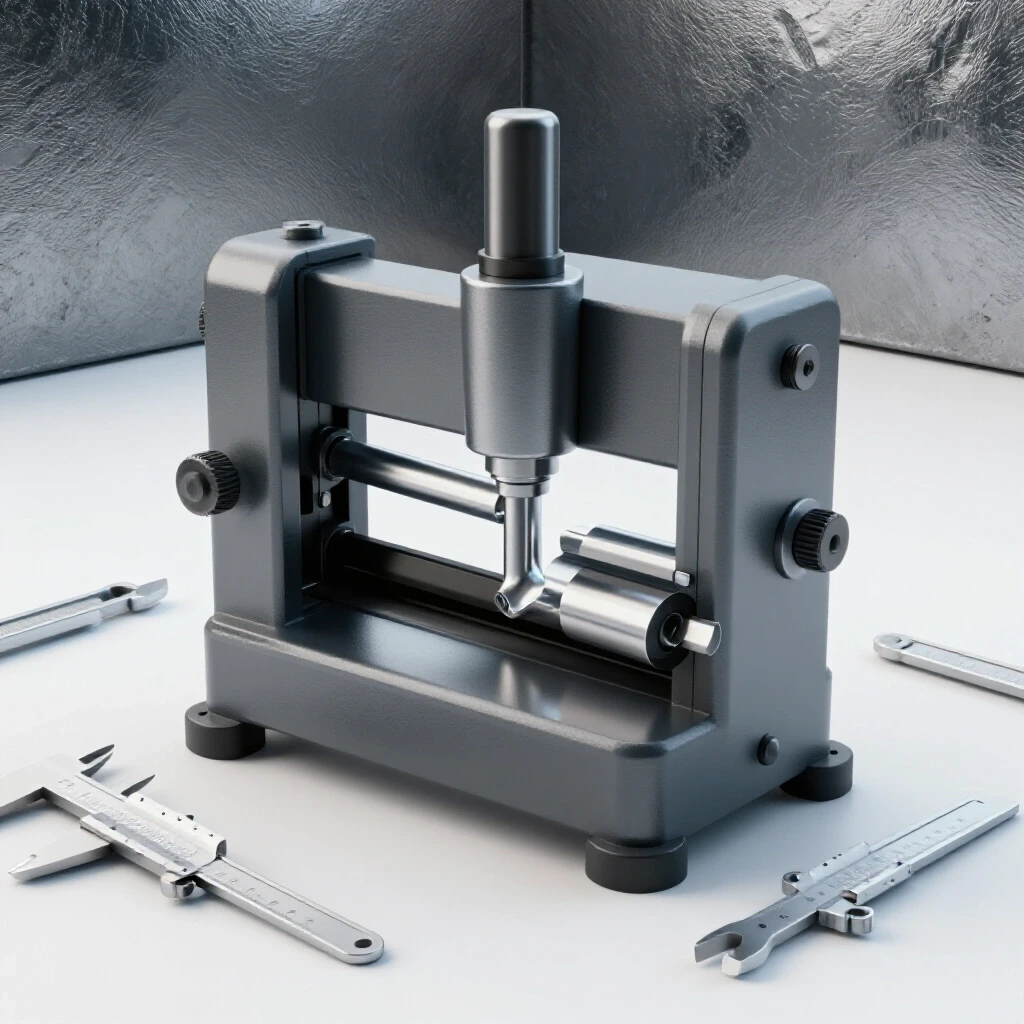
This guide focuses on the reality of the shop floor. We will look at how to source 1/4-inch to 3/8-inch mild steel plate, how to account for the width of your saw blade during the layout, and how to sequence your welds so the heat doesn’t pull your jig into a pretzel. We aren’t aiming for perfection—metal is a living thing that moves when you heat it—but we are aiming for a tool that gets you within a 1/16-inch tolerance every single time.
Designing the Foundation of Your Compact Bending Attachment
Successful custom fabrication projects begin with a clear understanding of the forces at play. For a small-scale press tool, you are designing a system that must withstand several tons of concentrated pressure without flexing or shearing. This requires selecting the right material thickness and calculating your dimensions before the first spark flies.
Design planning is the phase where you determine the physical limits of your tool. For a unit designed to handle 6-inch wide material up to 1/8-inch thick, I recommend using 3/8-inch mild steel plate for the base and the punch. This thickness provides enough “meat” for deep weld penetration and resists the elastic deformation that occurs under hydraulic load.
Selecting Material for Structural Integrity
Choosing the right steel is the most important step in ensuring your tool doesn’t fail under pressure. Mild steel plate, specifically A36 grade, is the standard for workshop jigs and fixtures because it is easy to weld and has a predictable yield strength.
For a small press jig, I prefer 3/8-inch plate for the main structural members. While 1/4-inch can work for the side plates, the V-block and the upper punch take the brunt of the force. If the material is too thin, it will eventually “bowl” or curve in the center. This distortion makes it impossible to get a straight bend across the entire width of your workpiece.
Calculating Cutting Lists and Kerf Allowances
Accuracy in your final build starts with the “kerf,” which is the width of the material removed by your cutting tool. Whether you are using a bandsaw, a cold saw, or a plasma cutter, failing to account for this 1/16-inch to 1/8-inch gap will result in a tool that is too small or out of square.
When I plan my cuts, I use a “finish dimension” mindset. If I need a 6-inch base plate, I don’t just mark 6 inches and cut. I mark 6 inches plus the width of my blade. This ensures that after the cut, the physical piece of steel in my hand is exactly 6 inches. In a small assembly, a 1/16-inch error on three different parts can compound into a 3/16-inch misalignment, which is enough to make the upper punch hit the side of the V-die.
Table 1: Metal Kerf Allowances by Cutter Type
| Cutting Tool | Typical Kerf Width | Layout Adjustment |
|---|---|---|
| Abrasive Chop Saw | 3/32″ – 1/8″ | Add 1/8″ to mark |
| Portable Bandsaw | 0.025″ – 0.035″ | Add 1/32″ to mark |
| Plasma Cutter (Handheld) | 1/16″ – 3/32″ | Add 3/32″ to mark |
| Oxy-Acetylene Torch | 1/8″ – 3/16″ | Add 3/16″ to mark |
Building Workshop Jigs for Alignment and Squaring
A press tool is only as good as its alignment. If the top punch is not perfectly centered over the bottom V-die, your bends will be lopsided, and you risk “camming” the tool, which can cause it to eject from the press under load.
Workshop jigs and fixtures are temporary or permanent structures used to hold parts in the exact position required for assembly. For this project, you will need a simple layout fixture—often just a flat welding table and some heavy-duty C-clamps—to ensure the side guides remain perpendicular to the base plate during the tack-welding process.
Setting Up the V-Die Base
The bottom of your press brake is typically a V-shape created by two pieces of angle iron or two plates welded at an angle. For a DIY version, welding two pieces of 1-inch by 1-inch angle iron (1/4-inch thick) onto a flat base plate is a reliable method.
I start by drawing a centerline on my 3/8-inch base plate using a carbide scriber. A Sharpie is too thick; the line itself can be 1/32-inch wide, which introduces error. I align the “peak” of the angle iron with this centerline. To keep them from sliding when I apply the first tack weld, I use “bridge tacks”—small welds that jump the gap between the workpiece and a scrap block of steel clamped to the table.
Constructing the Upper Punch and Guide System
The upper punch is the part that moves. It needs to be perfectly vertical. I use a piece of 3/8-inch plate with the bottom edge ground to a slight radius. A sharp edge on the punch will “score” or cut into your 1/8-inch sheet metal, creating a failure point in the bend.
To keep the punch aligned, you need guide rods or side plates. I prefer side plates because they offer more surface area to combat twisting. These plates must be welded at exactly 90 degrees to the base. If they lean even one degree, the punch will bind as it moves down. I use a machinist’s square to check this at every step, even after the first tack weld.
Mastering Weld Sequencing and Distortion Control
The biggest challenge in any custom fabrication project is heat. When you weld, the steel expands. As the weld cools, it shrinks, pulling the metal toward the bead. This is known as angular weld shrinkage, and it can easily pull a square frame out of alignment.
Weld sequencing layout is the planned order in which you apply welds to balance the heat and the resulting pull. By strategically placing welds on opposite sides of a joint, you can use the shrinkage of the second weld to pull the part back into the position it was in before the first weld moved it.
The Importance of Tack Weld Sizing
A common mistake is making tack welds too small. A tiny “sugar” tack will snap the moment the metal starts to move from the heat of the main weld. For 3/8-inch plate, your tacks should be about 1/4-inch long and have good penetration.
I space my tacks every two inches. Before I start the full beads, I check the squareness again. If the part has pulled, I can usually “cold-set” it (hit it with a hammer) or use the heat from the next tack to pull it back. Once you lay a full 6-inch bead, there is no moving it without a grinder and a lot of wasted time.
Executing the Weld Sequence
To keep the base plate flat, I never weld from one end to the other in a single pass. This “zips” the metal and creates a permanent curve. Instead, I use a “back-stepping” or “staggering” technique.
Table 2: Weld Sequencing for Distortion Control
| Sequence Step | Action | Purpose |
|---|---|---|
| 1. Center Tacks | Place 1/4″ tacks at the center of all joints | Establishes the primary pivot point |
| 2. End Tacks | Place tacks at the outer corners | Locks the overall dimensions |
| 3. Staggered Beads | Weld 1″ on the left, then 1″ on the right | Balances heat input across the part |
| 4. Opposite Side | Flip the part and repeat the sequence | Uses counter-shrinkage to keep it flat |
| 5. Cooling | Allow to air cool (do not quench in water) | Prevents brittle welds and extreme warping |
Final Assembly and Maintaining Tight Dimensional Tolerances
Once the welding is complete, the tool must be checked for dimensional tolerances. In the world of DIY fabrication, a tolerance of +/- 1/16th of an inch is usually the goal for a functional shop tool. If your punch is off by more than this, your bends will not be repeatable.
Maintaining tight dimensional tolerances involves checking the alignment of the punch within the V-die. I place the punch into the guide system and lower it until it rests in the V-block. If there is a gap on one side, it means the guide plates warped during welding. You can often correct minor errors by “chasing” the warp with a small bead of weld on the opposite side to pull it back, or by carefully grinding the guide surfaces.
Testing with 1/8-Inch Material
The true test of your compact bending attachment is how it handles a piece of 1/8-inch mild steel. I start with a scrap piece 2 inches wide. I mark a line, align it with the center of the V-die, and apply pressure with the hydraulic jack.
What I am looking for is “springback.” Metal is elastic; when you release the pressure, the bend will open up slightly. For 1/8-inch mild steel, you usually get about 1 to 3 degrees of springback. If my tool allows the punch to go deep enough into the V, I can “over-bend” the part slightly to reach a perfect 90 degrees.
Troubleshooting Common Alignment Issues
If your bends are “walking” (the line of the bend is not parallel to the edge of the plate), your V-die is likely not parallel to your guides. This is a common layout error.
- Check the V-die: Use a dial caliper to measure the distance from the guide plate to the V-die at both the front and the back.
- Check the Punch: Ensure the punch isn’t leaning forward or backward.
- Check the Base: Place the tool on a known flat surface (like a table saw top or a thick steel plate). If it rocks, the base plate has warped. You can often fix this by welding a “stiffener” (a piece of flat bar on edge) to the bottom of the base.
Advanced Tips for Accurate Square Cuts and Layouts
To get those accurate square cuts that make assembly easy, you have to look at your tools. A standard chop saw has a lot of “blade wander” because the thin abrasive disc flexes. If you are using one, don’t force the cut. Let the weight of the saw do the work.
For metal layout tips, I always suggest using a “scribe and dye” method. If you don’t have layout fluid (Dykem), a blue permanent marker works. Coat the steel, then use your square and a sharp scribe to scratch your line into the ink. This gives you a hair-thin line to follow, which is much more accurate than a thick pencil or soapstone mark.
Managing Thermal Expansion in Small Parts
When you are welding a tool that is only 6 or 8 inches wide, the entire piece of steel gets hot very quickly. This is different from welding a large trailer frame where the heat can dissipate.
In a small build, I often use “heat sinks.” These are just thick blocks of scrap copper or aluminum clamped near the weld zone. They soak up the excess heat and help prevent the 3/8-inch plate from reaching the temperature where it starts to lose its structural shape. If you don’t have copper, even a large chunk of scrap steel clamped to the base can help pull heat away.
Conclusion: Putting Your Tool to Work
Building a compact bending attachment is a rite of passage for many backyard fabricators. It moves you away from the “hammer and vise” method and into the world of precision metalwork. By focusing on material prep, kerf allowances, and smart weld sequencing, you can build a tool that rivals commercial options in terms of durability and accuracy.
The key is to take it slow. Spend 70% of your time on the layout and 30% on the actual welding. If your tacks are square and your heat is managed, the final product will be a reliable addition to your shop. Once you have this tool, you’ll find yourself designing projects specifically to use it—custom battery boxes, gussets for frames, and specialized brackets that once seemed impossible to make.
Next Steps for Your Build
- Source your 3/8-inch plate and 1/4-inch angle iron from a local steel supplier.
- Clean the mill scale off the steel using a flap disc; you cannot get a quality weld through the grey oxide layer.
- Scribe your centerlines and clamp your parts for the first set of tacks.
- Follow the staggered weld sequence to keep the base plate flat.
- Run a test bend on 1/8-inch scrap and adjust your technique for springback.
FAQ: Common Questions About Building Bending Attachments
What is the best material thickness for a DIY press brake? For a small shop press, 3/8-inch mild steel is the best balance between strength and weight. It is thick enough to resist bending under 10-20 tons of pressure but can still be cut and welded with standard garage tools.
How do I prevent the base plate from warping during welding? Use a staggered weld sequence. Instead of one long bead, weld in 1-inch increments, jumping from one side of the part to the other. This balances the heat and the cooling “pull” of the welds.
Why are my bends not coming out square? This is usually due to the punch not being centered over the V-die. Check your layout with a machinist’s square and ensure your guide plates are 90 degrees to the base. Even a 1/16-inch offset can cause an uneven bend.
Can I use this tool for 1/4-inch thick steel? This specific design is optimized for up to 1/8-inch material. Bending 1/4-inch steel requires a much wider V-die opening (usually 2 inches or more) and significantly more hydraulic force, which may exceed the limits of a small DIY jig.
What is “springback” and how do I account for it? Springback is the tendency of metal to return to its original shape after being bent. To get a 90-degree bend, you often have to bend the metal to 92 or 93 degrees. Your V-die should be deep enough to allow for this “over-bending.”
Do I need to heat the metal before bending? For 1/8-inch mild steel, no heat is required. Cold bending is actually more accurate because you don’t have to worry about the metal’s properties changing or the part warping as it cools after the bend.
How do I calculate the “bend allowance”? Bend allowance is the amount of material used in the curve of the bend. For 1/8-inch steel with a tight radius, a good rule of thumb is that the “inside” of the bend will shrink and the “outside” will stretch. Many fabricators just add 1/2 the thickness of the material to their layout for each 90-degree bend.
What kind of welding process is best for this project? MIG (GMAW) is excellent for this because it provides good penetration and is fast, which helps limit the total “heat soak” into the part. However, a stick welder (SMAW) with 7018 rods will also produce a very strong, structural tool.
How tight should the guide plates be? You want the punch to slide freely but without side-to-side “slop.” Aim for a gap of about 1/32-inch on either side of the punch. If it’s too tight, the heat from bending will cause it to bind.
How do I know if my shop press is strong enough? Most 12-ton or 20-ton shop presses are more than enough for bending 6-inch wide, 1/8-inch thick steel. You will feel the jack get firm, but you shouldn’t have to “bounce” on the handle. If you do, your V-die opening might be too narrow.
(This article was written by one of our staff writers, Robert Kline. Visit our Meet the Team page to learn more about the author and their expertise.)