How to Build a Precision Level Stand for Surface Plates (Fix)
I remember the first time I built a heavy-duty utility trailer frame in my garage. I had spent hours measuring, cutting, and squaring the main rails. I felt confident. However, as soon as I finished the final corner welds and let the metal cool, I noticed a massive problem. One corner had lifted nearly half an inch off the floor. The heat from my welder had pulled the entire structure out of alignment. That was the day I realized that in custom fabrication, the metal is alive—it moves, breathes, and fights you if you don’t have a plan to control it.
To solve this, I knew I needed a dead-level reference point in my shop. Most garage floors are sloped for drainage, which makes them terrible for layout work. I decided to construct a heavy-duty, adjustable support frame for my granite inspection block. This project taught me more about weld sequencing and distortion control than any other build. If you want to produce straight, accurate work, you need a base that doesn’t lie to you.
Designing the Foundation: Material Selection and Loading
Choosing the right steel for a stable inspection base is the first step in ensuring long-term accuracy. You need materials that offer high rigidity to prevent the frame from flexing under the weight of a heavy stone or cast iron plate.
I prefer using 2-inch or 3-inch square structural tubing with a wall thickness of at least 3/16 of an inch. Thinner walls tend to vibrate more and are harder to weld without blowing through or causing excessive warping. For the legs, I often use the same material, but I ensure the base is wider than the top to lower the center of gravity. This prevents the stand from tipping or swaying when you are leaning over it to mark a workpiece.
Calculating Material Requirements and Weight Distribution
A layout support must handle the static load of the plate and the dynamic load of the parts you place on it. You must calculate the total weight to ensure the floor and the stand can support it without sinking or bowing.
Most granite plates are heavy, often weighing several hundred pounds. I calculate the weight by multiplying the volume of the plate by the density of the material (granite is roughly 165 pounds per cubic foot). Once I have that number, I design the frame to handle at least three times that weight. This “over-engineering” isn’t just for safety; it provides the mass needed to dampen vibrations from nearby machinery, which can interfere with sensitive measurements.
Why Material Thickness Matters for Stability
Thicker steel dissipates heat more evenly during the welding process, which helps reduce the “pull” that causes frames to twist. It also provides more surface area for the threaded adjustment mechanisms we will install later.
In my experience, using 1/4-inch wall tubing for the top perimeter of the stand is ideal. This thickness allows you to grind the weld joints flat without compromising the structural integrity of the tube. It also gives you plenty of “meat” to drill and tap holes if you decide to bolt accessories or tool trays directly to the frame later.
Precision Cutting and Kerf Management
Accurate cuts are the bedrock of a square frame. If your initial pieces are even 1/16 of an inch off, that error will multiply as you assemble the stand, leading to a structure that is difficult to level.
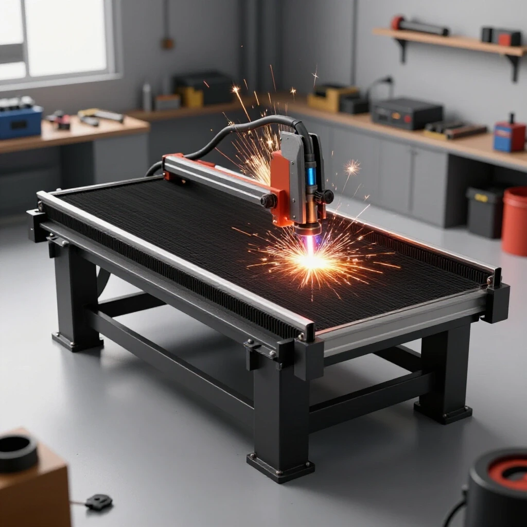
Kerf is the width of the material removed by the cutting tool, such as a saw blade or a plasma torch. If you don’t account for the kerf, your finished parts will always be shorter than your plans intended. For a standard abrasive chop saw, the kerf is usually about 1/8 of an inch. For a cold saw or a bandsaw, it might be closer to 0.040 or 0.060 inches. I always measure and mark my “cut side” to ensure the blade stays on the waste side of the line.
Table: Metal Kerf Allowances by Cutter Type
| Cutter Tool Type | Typical Kerf Width | Dimensional Tolerance | Best Use Case |
|---|---|---|---|
| Abrasive Chop Saw | 0.125 in (1/8″) | +/- 0.062 in | Rough structural cuts |
| Portable Band Saw | 0.035 – 0.045 in | +/- 0.031 in | Precise fit-ups |
| Cold Saw | 0.060 – 0.090 in | +/- 0.010 in | High-precision machining prep |
| Plasma Cutter (Hand) | 0.150 – 0.200 in | +/- 0.125 in | Plate breakdown only |
Mastering the Square Cut
To get a truly square cut, you must ensure your saw is calibrated. I never trust the built-in scales on most hobbyist chop saws. Instead, I use a machinist square to check the blade’s angle relative to the fence before every major project.
When I’m cutting the four main rails for a leveling support, I often clamp them together and cut them at the same time. This ensures that even if my cut is slightly off-angle, the pieces are at least identical in length. This “gang cutting” technique is a lifesaver when you are trying to build a perfectly rectangular top frame. If the opposing rails aren’t exactly the same length, you will never get the frame to sit square, no matter how many clamps you use.
Building the Assembly Jig and Fixturing
A jig is a temporary structure or setup used to hold parts in the correct position while they are joined. Without a jig, the forces of the cooling weld will pull your parts out of alignment almost instantly.
Since most of us don’t have a professional $10,000 welding table, we have to get creative. I often use a thick, flat piece of plate steel on a pair of heavy-duty sawmilling horses as my temporary jig. I use “F-style” clamps and magnetic squares to lock the pieces in place. Interestingly, I’ve found that over-clamping can sometimes be as bad as under-clamping. If you lock a piece too tightly, the stress builds up in the weld and can cause the metal to crack or “spring” violently when the clamps are removed.
Creating a Level Working Surface
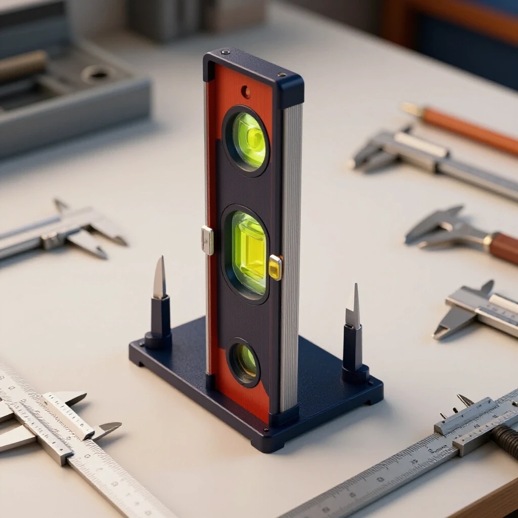
Before you start layout, you need to ensure your working surface is as flat as possible. I use a long machinist’s level to check my temporary table in multiple directions.
If the table isn’t level, I use thin metal shims (even pieces of soda cans work in a pinch) to get it close. Building an adjustable reference mount on a crooked surface is like trying to build a house on sand. You might get the stand square to itself, but you’ll struggle to get it level to the world once it’s finished. I aim for a tolerance of +/- 1/16 of an inch across a four-foot span during this phase.
The Importance of Tack Welding
Tack welds are small, temporary welds used to hold components in place before the final beads are laid. They act as “fuses” that allow you to check your work and make adjustments.
I never fully weld a joint until the entire frame is tacked together and checked for squareness. For 3/16-inch tubing, I use tacks that are about 1/4 inch long. I place them on the corners of the joints first. If I see that the frame is pulling one way, I can usually “cold-set” it (hit it with a dead-blow hammer) to move it back into place before the tacks get too strong.
Weld Sequencing and Distortion Control
Weld sequencing is the specific order in which you apply welds to a structure to balance the heat and minimize warping. As metal cools, it shrinks, and this shrinkage creates a powerful “pull” on the surrounding material.
If you weld all the way around one joint before moving to the next, that corner will shrink and pull the rest of the frame toward it. To combat this, I use a “stitching” method. I weld a small section on one corner, then move to the diagonally opposite corner. Building on this logic, you are essentially using the shrinkage of one weld to counteract the shrinkage of another. This is the most critical part of constructing a stable layout fixture.
Table: Weld Sequencing and Distortion Control
| Step | Action | Purpose | Result |
|---|---|---|---|
| 1 | Primary Tacks | Secure corners at 90 degrees | Holds basic geometry |
| 2 | Diagonal Check | Measure corner-to-corner | Confirms squareness |
| 3 | Opposing Flats | Weld outside flats in X-pattern | Balances longitudinal pull |
| 4 | Vertical Downs | Weld vertical seams | Seals joints without high heat |
| 5 | Inside Corners | Final interior beads | Completes structural bond |
Managing Heat Input
The more heat you put into the metal, the more it will move. I try to keep my weld beads short—usually no more than two inches at a time.
As a result of this approach, the metal has time to dissipate heat between passes. I also avoid “weaving” the torch unless necessary. A straight stringer bead puts less total heat into the base metal than a wide weave. If the steel starts to glow dull red far away from the weld, you are moving too slowly or using too much amperage. I often keep a wet rag nearby to cool the areas around the weld, though I never quench the weld itself, as that can make the steel brittle.
Threaded Adjustment Mechanisms for Leveling
A precision stand is only as good as its ability to be leveled. Since no floor is perfectly flat, you must incorporate threaded feet that allow for fine-tuned adjustments.
For my stands, I use heavy-duty Grade 8 bolts (usually 3/4-inch or 1-inch diameter) as the leveling legs. I weld a thick nut or a threaded “bung” into the bottom of each leg. Interestingly, I prefer a three-legged design for smaller stands. In geometry, three points define a plane, which means a three-legged stand will never wobble. For larger, heavier plates, a four-legged stand is necessary for stability, but it requires much more care to level correctly.
Fabricating Custom Leveling Feet
Standard bolts can mar a floor or slip. I like to fabricate “pucks” or footpads to go on the end of the threaded rods.
I take a piece of 3-inch round bar stock, about 1/2 inch thick, and drill a shallow hole in the center. I then grind the end of the leveling bolt into a slight radius (a ball shape). The bolt sits in the hole of the puck, allowing the foot to pivot slightly if the floor is uneven. This ensures that the weight of the stand is distributed across the entire surface of the footpad rather than just on the edge of a bolt.
Thread Engagement and Load Bearing
When you are supporting a 500-pound granite block, you need to ensure the threads in your leveling feet won’t strip or gall.
I make sure I have at least 1.5 times the diameter of the bolt in “thread engagement.” For a 3/4-inch bolt, that means the threaded nut or bung should be at least 1-1/8 inches long. If the tubing wall is too thin to provide this, I weld a “doubler plate” or a longer piece of threaded pipe inside the leg. I also apply a generous amount of anti-seize lubricant to the threads. Without it, the weight of the plate can cause the threads to “cold weld” together over time, making future adjustments impossible.
Final Assembly and Vibration Damping
The final stage involves mounting the reference surface to the frame. You cannot simply bolt a granite plate to a steel frame; the two materials expand and contract at different rates, which can cause the plate to crack.
I use a “point-contact” system. I place three small pads of hard rubber or specialized vibration-damping material between the stand and the plate. These pads should be positioned according to the manufacturer’s “support points”—usually located at a specific distance from the ends of the plate (often 20% of the length). This prevents the plate from sagging under its own weight and isolates it from shop floor vibrations.
Post-Weld Alignment and Straightening
Even with the best sequencing, some distortion is inevitable. Once the frame is fully cooled, I perform a final check with a precision level and a straightedge.
If I find a slight twist, I use “flame straightening” or mechanical force to correct it. Flame straightening involves heating a small spot on the “long” side of a warp and then cooling it quickly with water. This causes the heated area to shrink more than the surrounding metal, pulling the frame back into alignment. It’s a delicate process, but it’s a standard technique in chassis fabrication and high-end tool making. I only use this for errors larger than 1/8 of an inch; anything smaller can usually be handled by the leveling feet.
Finishing for Longevity
A workshop fixture is prone to rust from humidity and coolant. I always clean the steel with a wax and grease remover before applying a high-quality primer and enamel paint.
I leave the top surfaces of the leveling feet and the mounting points bare or lightly oiled. This allows for better contact and easier adjustments. I also like to add a lower shelf to the stand using expanded metal or thin plate. This doesn’t just provide storage; it adds a massive amount of diagonal bracing to the legs, which significantly increases the overall rigidity of the structure.
FAQ: Precision Leveling Stands and Fabrication
Why shouldn’t I just weld the stand together on my garage floor? Most garage floors have a slope of at least 1 inch every 10 feet for drainage. If you build on this surface, your frame will likely have a “built-in” twist. Always use a leveled jig or a known flat surface like a thick steel plate on horses.
What is the best way to check for squareness on a large frame? The “3-4-5 rule” is good, but measuring diagonals is better. Measure from the top-left corner to the bottom-right, then from top-right to bottom-left. If the numbers are within 1/16 of an inch, your frame is square.
Can I use casters on a precision stand? You can, but they must be “leveling casters.” These have a rubber foot that can be wound down to lift the wheel off the ground. Standard wheels vibrate and move, which ruins the accuracy of your measurements.
How do I prevent the “pull” when welding the legs to the top frame? Tack the legs on the outside corners first. Then, weld the “inside” of the joint. The inside weld will pull the leg “in,” which is easier to correct with a brace than if the leg pulls “out.”
Why do you recommend three mounting points for the plate? Three points will always contact the plate, regardless of how the stand is twisted. If you use four points, one corner will almost always have a tiny gap, leading to vibration or “rocking” of the plate.
Is 11-gauge (1/8″) tubing thick enough for a stand? It depends on the plate size. For a small 12×18 inch plate, it’s fine. For a 24×36 inch granite block, I recommend at least 3/16″ or 1/4″ wall tubing to prevent the legs from “ringing” or flexing.
How do I account for the weight of the granite when leveling? Always level the stand after the plate is installed. The weight of the stone will compress the floor or settle the stand, potentially changing your level readings.
What should I do if my threaded feet are hard to turn? This usually means the threads are galled or the load is too high. Use a floor jack to slightly lift the corner of the stand before turning the leveling bolt. Always use anti-seize.
How often should I re-check the level of my stand? In a garage environment, temperature swings can move the floor. I check my reference surface every time I start a high-precision project, or at least once a month.
Can I use C-channel instead of square tubing? Yes, C-channel is very rigid, but it is harder to keep square during welding because it is asymmetrical. Square tubing is much more “user-friendly” for DIY builders because it reacts to heat more predictably.
What is the “neutral axis” in a weld? This is the center line of a part where the forces of expansion and contraction are balanced. When you weld off-center (like on one side of a tube), you create an imbalance that causes the part to curve.
How do I stop my stand from “walking” across the floor? The weight of the plate usually holds it in place, but using rubber-bottomed pucks on your leveling feet provides enough friction to keep the stand stationary even if you are hammering on the workpiece.
(This article was written by one of our staff writers, Robert Kline. Visit our Meet the Team page to learn more about the author and their expertise.)