How to Build a Rigid Stand for Hydraulic Pipe Benders (Fix)
I still remember the first time I built a heavy-duty shop fixture. I had spent three days meticulously measuring and cutting 2×2-inch square tubing for a mobile base. I was proud of my tight tolerances and clean miters. However, as soon as I finished the final corner weld, the entire frame pulled nearly half an inch out of square. It sat on the shop floor like a rocking chair. That day taught me that fabrication is not just about where you put the metal; it is about how you manage the physics of heat and the mechanical forces of the tools you intend to mount.
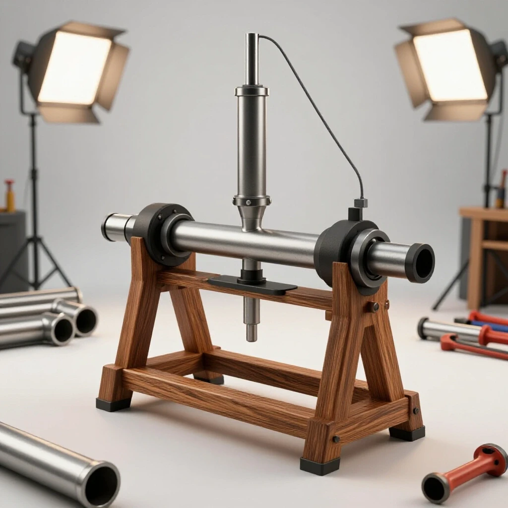
When you are building a reinforced structure designed to withstand the immense pressure of a hydraulic ram, you cannot afford a frame that flexes or twists. A hydraulic unit can exert several tons of force, and if your mounting platform is not rigid, that energy will go into deforming your stand rather than doing the work. In this guide, I will break down how to construct a rock-solid, stationary base that maintains its dimensional integrity through smart layout, strategic clamping, and controlled weld sequencing.
Designing the Foundation for High-Force Equipment
Designing a structural base requires calculating the footprint of the tool and the expected load paths to ensure the metal can handle the stress without bending. This phase involves selecting material wall thickness and planning the overall dimensions to provide a stable center of gravity during operation.
When I start a custom fabrication project, I look at the base footprint of the hydraulic unit first. Most of these units have a specific bolt pattern. I prefer using 3/8-inch or 1/2-inch thick mild steel plate for the mounting surface. This thickness prevents the plate from “oil-canning” or bowing when the hydraulic cylinder is under full load. For the legs and frame, 2×2-inch square tubing with a 3/16-inch wall thickness (7-gauge) offers a great balance between weight and torsional rigidity.
Before you buy your steel, draw a 1:1 scale layout on your shop floor or a dedicated welding table using a soapstone marker. This allows you to visualize the bracing. You need to account for the “swing” or movement of any arms associated with your equipment. If the stand is too narrow, the force of the hydraulics could tip the entire assembly over. I generally aim for a base footprint that is at least 25% wider than the tool itself to ensure a stable foundation.
Calculating Kerf and Material Allowances for Accurate Square Cuts
Kerf is the width of the material removed by a cutting tool, such as a saw blade or a plasma torch. Accurate square cuts depend on accounting for this lost material during the measurement phase to ensure that finished components meet the exact dimensions specified in the build plan.
One of the biggest mistakes I see builders make is measuring and marking their cuts without considering the blade thickness. If you are using a dry-cut chop saw, your blade might be 0.080 inches thick. Over four cuts, that is nearly 3/8 of an inch of “missing” metal. This leads to gaps in your joints that you then have to fill with weld wire, which increases heat input and causes more warping.
| Cutting Tool Type | Typical Kerf Width (Inches) | Best Use Case |
|---|---|---|
| Abrasive Chop Saw | 0.125″ – 0.150″ | Rough structural cuts |
| Dry-Cut Carbide Saw | 0.080″ – 0.095″ | Precision framing and miters |
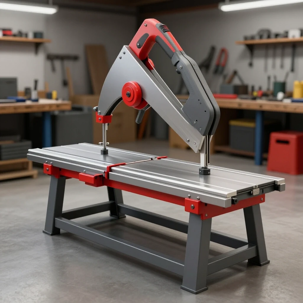
| Horizontal Bandsaw | 0.035″ – 0.042″ | High-accuracy production cuts |
| Oxy-Fuel Torch | 0.060″ – 0.100″ | Thick plate (1/2″ and up) |
| Plasma Cutter | 0.040″ – 0.060″ | Complex shapes and gussets |
To get accurate square cuts, I always mark my line and then align the blade so it “leaves the line” on the workpiece. If you cut down the center of your mark, your piece will be short by half the kerf width on both ends. When building a stand that needs to be level, even a 1/16-inch error in leg length will cause a noticeable wobble.
Why Workshop Jigs and Fixtures are Essential for Squaring
Workshop jigs and fixtures are temporary or permanent tools used to hold workpieces in a fixed position during assembly. They provide a physical stop or clamp point that prevents metal from moving, ensuring that the finished project remains square and true to the original design.
You cannot rely on your hands or a simple speed square to hold parts while you weld. The moment the arc strikes, the metal begins to expand. As it cools, it contracts with a force that can easily overcome a hand-held clamp. I use a dedicated fixture table with 5/8-inch holes, but if you don’t have one, you can build a temporary jig on a flat section of your shop floor.
I suggest welding four small “L” brackets to your table at the exact outer dimensions of your base frame. These act as hard stops. By wedging your tubing against these stops, you force the frame to stay square during the tacking process. If you are working on a concrete floor, use heavy C-clamps or F-style clamps to secure your material to a known straight edge, like a piece of 4-inch I-beam or a heavy-duty workbench.
Managing Metal Warping Solutions through Strategic Tacking
Metal warping solutions involve techniques like tack welding and heat management to control the inevitable expansion and contraction of steel. Tacking involves placing small, localized welds at key intersections to lock the geometry in place before the final, high-heat welding passes are made.
Tack welds are the “pins” that hold your project together. For a stand made of 2-inch tubing, I use 1/4-inch long tacks on all four sides of every joint. A common mistake is only tacking the top and bottom. If you do that, the joint will “hinge” and pull inward when you weld the sides.
- Tack Spacing: Place tacks at the corners first, then check for square.
- Tack Size: Make them strong enough to hold, but small enough to be consumed by the final weld bead.
- The “X” Measurement: Always measure the diagonals of your frame after tacking. If the measurements are within 1/16 of each other, you are ready to proceed. If not, you can usually “cold-set” the frame by giving it a sharp wrap with a dead-blow hammer before the final welds.
Mastering the Weld Sequencing Layout to Control Distortion
Weld sequencing layout refers to the specific order and direction in which weld beads are applied to a structure. By alternating sides and directions, a fabricator can use the shrinkage of one weld to counteract the pull of another, maintaining the overall alignment of the project.
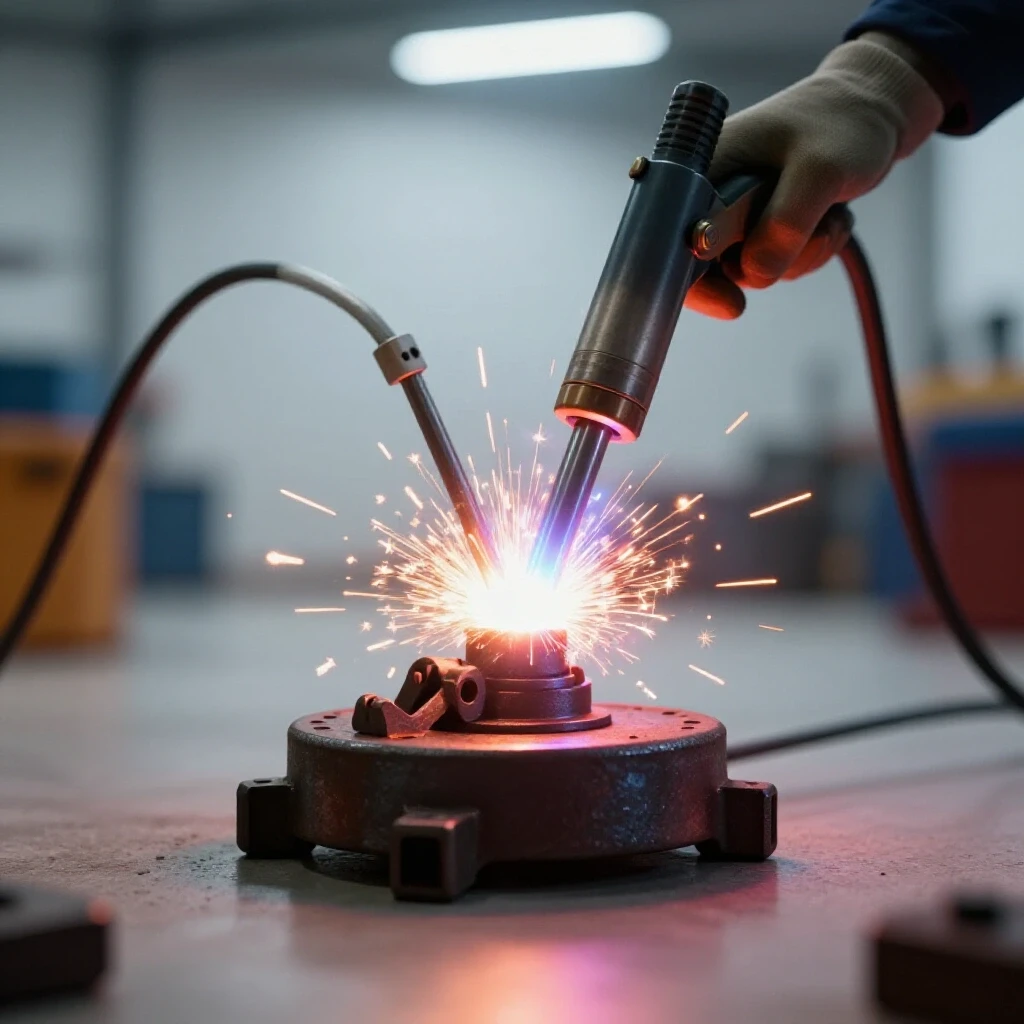
Welding creates a massive amount of localized heat. As the puddle cools, it shrinks. If you weld all the way around one joint before moving to the next, that corner will pull the entire frame toward it. To build a rigid mounting platform, you must use an alternating sequence. Think of it like tightening the lug nuts on a car tire; you never go in a circle.
I follow a “cross-pattern” sequence. If I have a rectangular base, I weld the outside of the front-left corner, then the outside of the back-right corner. Next, I do the front-right and then the back-left. By jumping across the frame, the heat is distributed evenly, and the cooling forces pull against each other rather than compounding in one direction.
The Back-Stepping Technique
For long seams, such as attaching a 1/2-inch mounting plate to the frame, I use the back-stepping method. Instead of welding from left to right in one continuous bead, I start two inches in and weld back toward the start. Then I move another two inches ahead and weld back to the previous bead. This technique significantly reduces the total heat buildup in one area, which is the primary cause of plate warping.
Structural Triangulation and Bracing for Torsional Strength
Structural triangulation is the practice of adding diagonal members to a frame to create triangles, which are inherently more rigid than squares or rectangles. This prevents the stand from twisting or “racking” when subjected to the lateral and vertical forces of a hydraulic system.
A simple four-legged stand is prone to racking. When the hydraulic ram pushes down, the legs want to splay out. To prevent this, I incorporate diagonal bracing on at least three sides. I use 1.5×1.5-inch tubing or 1/4-inch thick flat bar for these braces. By cutting the ends at 45-degree angles and welding them from the bottom of one leg to the top of the next, you turn a flexible rectangle into two rigid triangles.
For the mounting plate itself, I often add gussets. A gusset is a triangular piece of plate steel welded into a corner. If your hydraulic unit sits on a central pedestal, welding four gussets at 90-degree intervals around the base of that pedestal will prevent it from leaning or vibrating during use.
Leveling and Adjusting the Base Footprint for Uneven Floors
Leveling involves the use of adjustable feet or shims to ensure the stand remains stable and plumb, even if the workshop floor is slanted. A stable base footprint is critical for high-pressure tools to ensure that the force is directed through the frame and into the ground safely.
No garage floor is perfectly flat. If you weld a stand and it wobbles, it might not be your welding—it might be the concrete. I always finish my heavy stands with adjustable leveling feet. I weld a 1/2-inch nut into the bottom of each leg and thread in a heavy-duty bolt with a wide washer welded to the head.
- Bolt Grade: Use Grade 5 or Grade 8 bolts for leveling feet to ensure the threads don’t strip under the weight.
- Foot Diameter: A 3-inch diameter foot provides better weight distribution and prevents the stand from “walking” during operation.
- Locking: Once the stand is level, tighten a second nut against the leg to lock the foot in place. This prevents vibration from backing the bolt out over time.
Post-Weld Inspection and Correcting Heat Distortion
Post-weld inspection is the process of checking all joints for penetration and verifying that the structure has remained within dimensional tolerances. If warping has occurred, mechanical or thermal straightening techniques are used to bring the project back into alignment.
Even with the best sequencing, some distortion is inevitable. I allow my projects to air-cool completely before removing them from the clamps or jigs. Never quench a structural weld with water; this makes the steel brittle and can lead to stress fractures.
If I find a slight bow in a long rail, I use “flame shrinking.” I use an oxy-acetylene torch to heat a small spot on the side opposite the bow. As that spot cools, it shrinks and pulls the metal back toward center. It is a subtle art that requires patience, but it is a standard practice in professional fabrication shops for correcting minor alignment issues.
Material and Cost Breakdown for a Heavy-Duty Stand
Keeping a detailed log of materials and costs helps in planning future custom fabrication projects and ensures that the build stays within budget. For a stand designed to hold a 10-ton to 20-ton hydraulic unit, the following is a realistic estimate of what I typically spend.
| Item Description | Quantity/Length | Estimated Cost (USD) |
|---|---|---|
| 2″ x 2″ x 3/16″ Square Tubing | 20 Feet | $120.00 |
| 1/2″ Mild Steel Mounting Plate | 12″ x 12″ | $45.00 |
| 1.5″ x 1/4″ Flat Bar (Bracing) | 10 Feet | $35.00 |
| Heavy-Duty Swivel Casters (Optional) | Set of 4 | $80.00 |
| Grade 8 Leveling Bolts and Nuts | 4 Sets | $25.00 |
| Welding Consumables (Wire/Gas) | N/A | $20.00 |
| Total Estimated Cost | $325.00 |
This cost is significantly lower than a high-end commercial stand, and because you are building it yourself, you can customize the height to your specific ergonomic needs. I usually set my mounting height so that the working area of the tool is at waist level, roughly 36 to 40 inches from the floor, to reduce back strain during long sessions.
Final Assembly and Surface Preparation
The final steps involve cleaning the metal, removing mill scale, and applying a protective finish. This not only makes the stand look professional but also prevents rust and makes it easier to spot any cracks that might develop over years of heavy use.
I use a flap disc on a 4.5-inch angle grinder to smooth out the weld beads, but I am careful not to grind them flush. Removing too much material weakens the joint. After grinding, I wipe the entire frame down with acetone to remove oils and then apply a coat of industrial-grade primer. A high-visibility color like safety orange or grey is practical for a shop environment.
Once the paint is dry, I bolt the hydraulic unit to the plate using hardened washers. I check the torque on these bolts after the first few uses, as the vibrations can sometimes cause the mounting hardware to settle.
Key Takeaways for Successful Fabrication
Building a rigid platform for heavy tools is a test of your layout and heat management skills. By following a structured approach, you can create a fixture that will last a lifetime in your shop.
- Plan for Kerf: Always account for the 1/16 to 1/8 inch of metal lost during the cutting process.
- Fixture Everything: Use hard stops and clamps to fight the internal stresses of the welding process.
- Sequence Your Welds: Never weld a single joint to completion all at once; jump around the frame to balance the pull.
- Triangulate for Strength: Rectangles are weak; triangles are strong. Use diagonal bracing to stop torsional twist.
- Check for Square Constantly: Measure your diagonals after every major set of welds.
Frequently Asked Questions
How do I know if my square tubing is truly square before I start?
I always check my raw stock with a machinist square. Sometimes factory tubing has a slight twist or the walls aren’t perfectly 90 degrees. If the stock is twisted, I use it for shorter braces where the twist won’t affect the overall geometry as much as it would on a long leg.
What is the best way to ensure all four legs are the exact same length?
The most reliable method is to clamp all four legs together in a bundle and cut them at the same time on a bandsaw or chop saw. This ensures that even if your measurement is off by a hair, all legs will be off by the same amount, keeping the stand level.
Why does my frame pull out of square even when I use clamps?
Clamps only hold the metal physically; they don’t stop the internal molecular contraction of the cooling weld. If you release the clamps too early, the metal will spring back. Leave the project clamped until it is cool enough to touch with your bare hand.
Should I MIG or TIG weld a structural stand?
MIG is usually preferred for structural stands because it is faster and provides excellent penetration on thicker materials like 3/16-inch tubing. TIG is great for precision but can actually introduce more heat into the part because the process is slower, which can lead to more warping if you aren’t careful.
Can I use thinner 1/8-inch wall tubing to save money?
For a light-duty workbench, 1/8-inch is fine. However, for a stand supporting hydraulic forces, the 1/8-inch wall can “crush” or deform at the bolt holes over time. The 3/16-inch wall provides a much more stable “meat” for the welds and mounting hardware.
How do I fix a “rocking” stand if I don’t have adjustable feet?
If the wobble is minor (less than 1/8 inch), you can sometimes use a shim made from a scrap piece of sheet metal. If it’s worse, you may need to cut one of the welds, realign the leg, and re-weld it. This is why adjustable feet are highly recommended.
What size tack weld is appropriate for 3/16-inch steel?
I generally aim for a tack that is about the size of a pea. It should have enough penetration to hold the weight of the part but be small enough that your final weld bead can easily flow over and incorporate it without leaving a hump.
Do I need to weld the inside corners of the tubing?
For maximum rigidity, yes. However, welding the inside corners is where most of the “pulling” happens. I usually weld the outside and the two sides first, then do the inside corners last with a lower heat setting to minimize the inward draw.
How do I prevent the mounting plate from bowing when I weld it to the frame?
Use the “stitch welding” method. Weld 2 inches, skip 4 inches, and repeat. Once the first set of stitches is cool, go back and fill in the gaps. This prevents a long, continuous heat line from curling the edges of the plate upward.
Is it better to bolt or weld the hydraulic tool to the stand?
Always bolt the tool. Welding the tool directly to the stand makes maintenance impossible and can damage the internal seals of the hydraulic unit due to heat transfer. Use Grade 8 bolts and nyloc nuts to ensure everything stays tight under vibration.
What is the 3-4-5 rule for squaring?
This is a geometric principle where if one side of a triangle is 3 units long and the adjacent side is 4 units long, the diagonal must be 5 units for the corner to be exactly 90 degrees. It is a foolproof way to check square on large frames where a small square isn’t accurate enough.
(This article was written by one of our staff writers, Robert Kline. Visit our Meet the Team page to learn more about the author and their expertise.)