How to Build a Non-Slip Mobile Steel Shop Ladder (DIY Plan)
There is a specific kind of frustration that only a fabricator understands. You spend hours measuring, cutting, and deburring your steel, only to watch your perfectly square frame pull into a diamond shape the moment you lay down a heavy bead. I’ve been there more times than I care to admit. Early in my career as a prototype technician, I once built a set of mobile stairs for a heavy equipment bay. I didn’t account for the pull of the welds on the tread supports, and by the time I was finished, the whole structure rocked like a chair with one short leg.
That experience taught me that successful custom fabrication projects aren’t just about melting metal together. They are about managing the physical forces of heat and tension. When you are building a mobile platform for shop use, you need it to be dead level and rock solid. If the base is warped, the locking casters won’t sit evenly on the floor, and you’ll feel that dreaded wobble every time you climb up to reach a tool on a high shelf.
In this guide, I’m going to walk you through the process of constructing a durable, rolling shop step-up. We will focus on how to maintain tight tolerances, control weld sequencing to prevent warping, and ensure the finished product is stable enough for daily workshop use.
Planning the Material Cut List and Kerf Allowances
Planning involves calculating every piece of steel needed, accounting for the material lost during cutting (kerf), and organizing lengths to minimize waste. This stage is where you prevent the “short board” syndrome that leads to gaps in your joints and weak welds.
Before I spark the saw, I always create a detailed cut list. For a project like this, I typically use 1-inch square tubing with a 1/8-inch wall thickness. It’s light enough to move but thick enough to handle the heat of a MIG welder without blowing through. When you are planning your cuts, you must account for the kerf. The kerf is the width of the material removed by the saw blade. If you use an abrasive chop saw, that kerf can be up to 1/8-inch. If you use a cold saw or a bandsaw, it might be closer to 1/16-inch.
If you have ten cuts to make and you ignore a 1/8-inch kerf, your final piece will be over an inch shorter than your plan intended. I always mark my lines and then cut on the “waste side” of the line. This ensures the finished part matches the dimension on my blueprint exactly.
| Cutter Type | Typical Kerf Width | Best Use Case |
|---|---|---|
| Abrasive Chop Saw | 3/32″ – 1/8″ | Rough framing, fast cuts |
| Horizontal Bandsaw | 0.035″ – 0.050″ | Precision angles, batch cutting |
| Cold Saw | 0.060″ – 0.090″ | High-precision, burr-free cuts |
| Plasma Cutter | 0.040″ – 0.125″ | Plate work, irregular shapes |
Building a Dedicated Layout Fixture for Frame Alignment
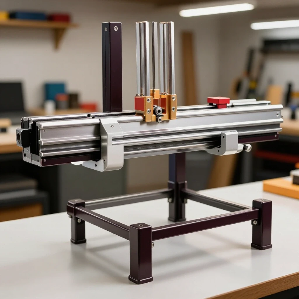
A layout fixture is a temporary or permanent jig that holds metal components in precise positions to prevent movement during the initial tacking process. Using a fixture is the only way to ensure that your base frame stays square before the final welding begins.
In my shop, I don’t trust my eyes to judge a 90-degree angle. I use a flat welding table and a set of heavy-duty steel squares. To build a reliable base for a mobile shop ladder, you should create a “perimeter jig.” This can be as simple as clamping four pieces of scrap angle iron to your table to create a frame that your project pieces sit inside.
When the tubing is locked into a fixture, it cannot “creep” as you bump it with the welding gun. I aim for a dimensional tolerance of +/- 1/16th of an inch across the diagonals. If the diagonals of your rectangular base are equal, the frame is square. If they are off by more than 1/8-inch, your casters will not track straight, and the ladder will feel unstable.
Managing Thermal Expansion and Weld Shrinkage Forces
Heat distortion occurs when metal expands during welding and contracts as it cools, pulling the structure out of alignment if not properly sequenced. Understanding this “pull” is the difference between a straight project and a twisted mess.
Metal is a dynamic material. When you apply a 2,000-degree arc to a joint, the steel expands. As the weld pool cools, it shrinks. This shrinkage acts like a tiny, powerful winch, pulling the two pieces of metal toward the side where the weld was placed. This is called angular distortion.
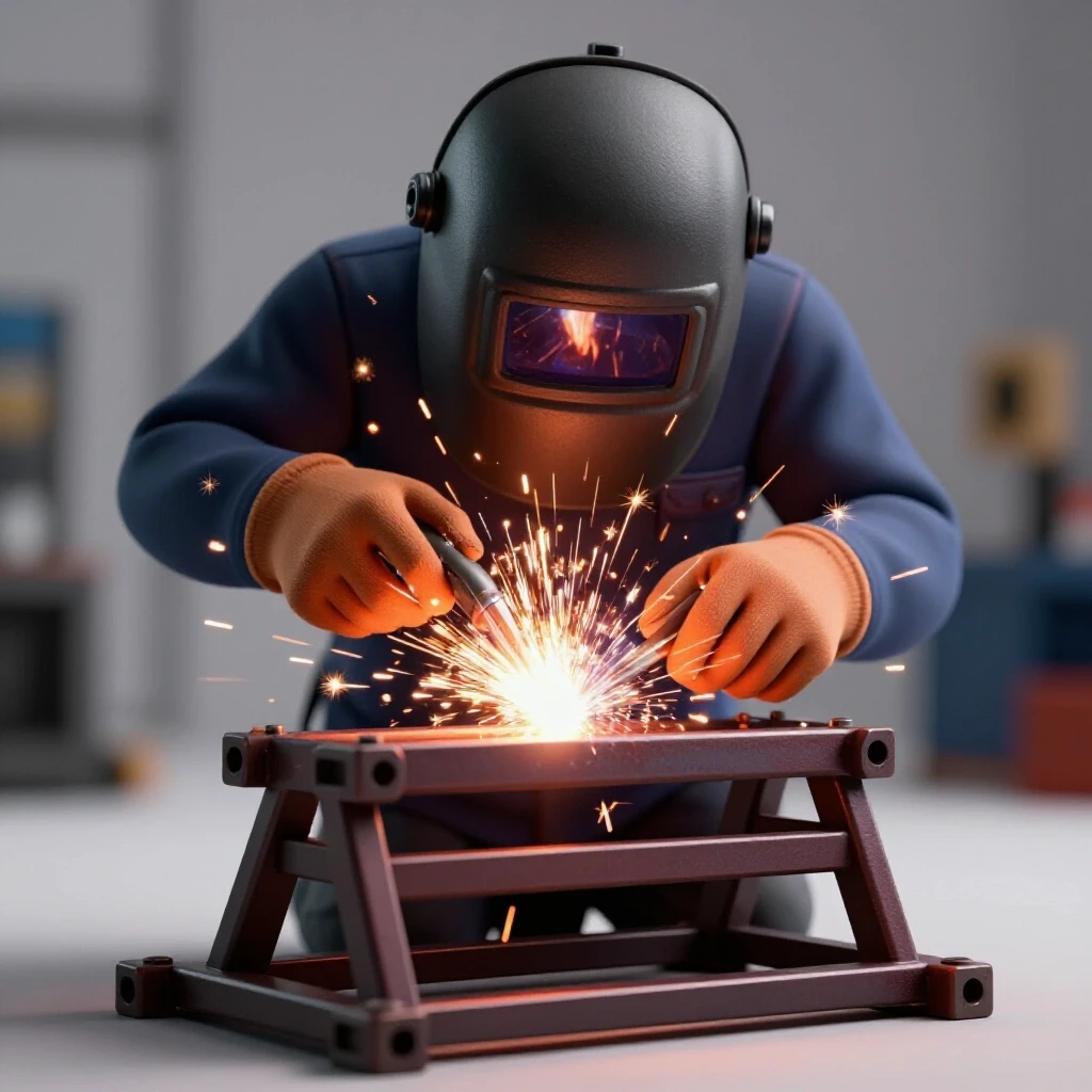
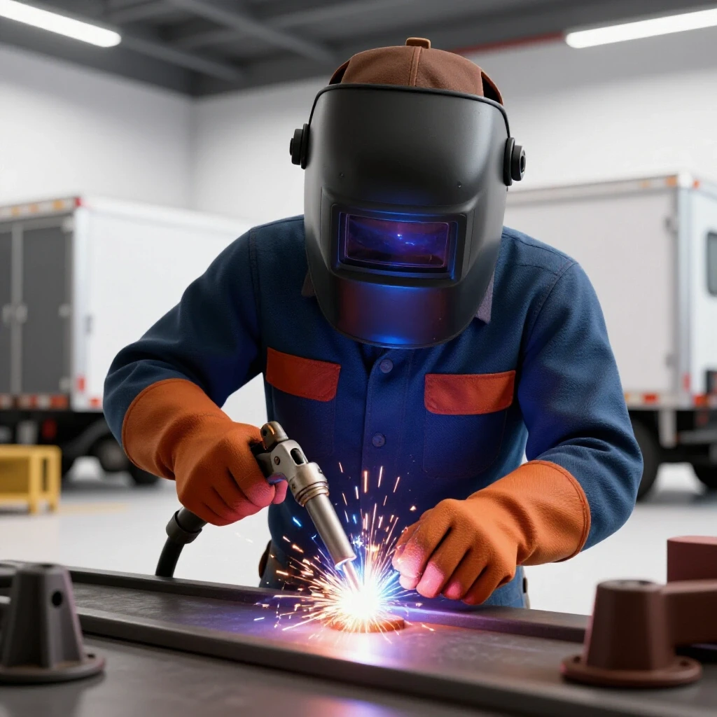
To combat this, I never weld one joint completely before moving to the next. I use a specific weld sequencing layout. I start with small, strong tack welds at every corner. A tack weld should be about 1/4-inch long and deep enough to penetrate both pieces. Once the frame is tacked, I check the square again. Only then do I begin the final passes, jumping from one corner to the opposite diagonal corner to balance the heat input across the entire structure.
Structural Tacking Strategies for Rigid Assemblies
Structural tacking is the process of placing small, strategic welds to hold an assembly together while allowing for minor adjustments before the final beads are run. It is the most critical step in maintaining the geometry of your custom fabrication projects.
When I’m setting up the uprights for the handrails or the step supports, I use the “four-point tack” method. On square tubing, I place one tack in the center of each of the four sides. This balances the tension. If you only tack one side, the cooling weld will pull the upright out of plumb by several degrees.
- Tack Size: Aim for a tack that is 2 to 3 times the thickness of the material.
- Tack Spacing: For long runs, place a tack every 3 to 4 inches.
- Sequence: Tack the corners first, then the midpoints.
- Inspection: Always use a level or a square after every four tacks to ensure nothing has shifted.
Why Weld Sequencing Prevents Frame Twisting
Weld sequencing is the planned order in which you apply weld beads to distribute heat evenly and minimize the cumulative pull of cooling metal. A proper sequence ensures that the forces of contraction cancel each other out.
Think of weld sequencing like tightening the lug nuts on a car wheel. You don’t go in a circle; you go in a star pattern. When welding the steps onto your shop ladder frame, you should weld the front left, then the back right, then the front right, then the back left. This prevents the heat from building up in one localized area, which is the primary cause of metal warping.
I’ve found that taking a break between passes also helps. If the steel becomes too hot to touch with a gloved hand, it is holding too much latent heat. This leads to “heat soak,” where the entire structure begins to expand and move unpredictably. I often use a large copper block as a heat sink near my joints to suck away excess thermal energy.
| Weld Type | Shrinkage Direction | Mitigation Strategy |
|---|---|---|
| Butt Weld | Longitudinal (Lengthwise) | Pre-set the gap 1/16″ wider |
| Fillet Weld | Angular (Pulls toward bead) | Back-step welding or double-sided tacks |
| Lap Weld | Transverse (Across the joint) | Heavy clamping to a fixture table |
| Corner Weld | Compound (Pulls inward) | Use internal bracing or gussets |
Installing Caster Mounting Plates for Maximum Stability
Caster mounting plates are flat steel sections welded to the base of the frame that provide a secure, level surface for attaching wheels. Proper alignment here ensures that the ladder remains mobile and doesn’t “crab” sideways when pushed.
For a shop ladder, you want locking casters. But even the best casters won’t work if the mounting plates are crooked. I use 1/4-inch thick plate for the mounts. This thickness prevents the plate from warping when I weld it to the thinner 1/8-inch wall tubing.
When welding these plates, I weld from the center out toward the edges. This pushes the heat away from the middle of the plate, keeping the mounting surface flat. If the plate cups, the caster swivel bearing will bind, and the ladder will be difficult to steer. I always check the plates with a straightedge after they cool. If there is a slight bow, I can usually tap it flat with a heavy hammer before bolting the casters on.
Working with Expanded Metal Grating for Non-Slip Surfaces
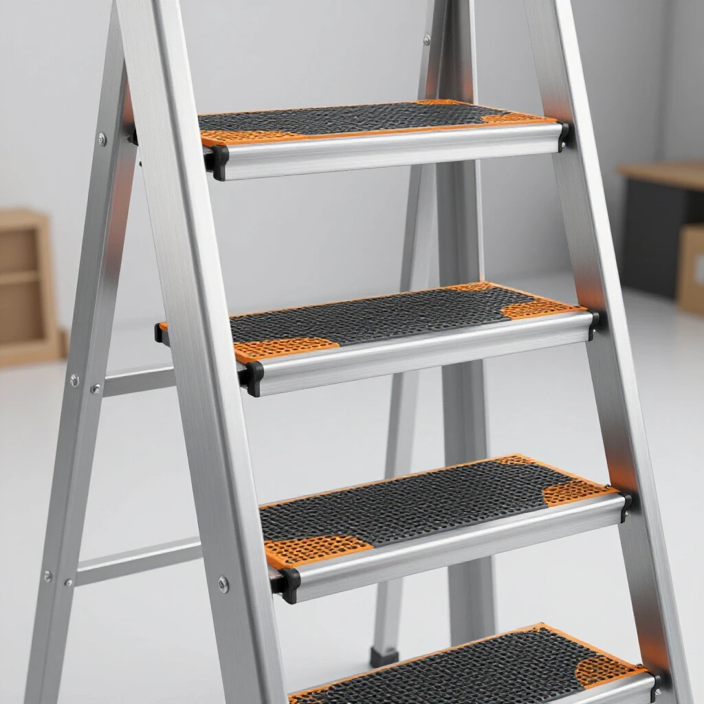
Expanded metal grating is a mesh-like steel product used for treads because it provides excellent grip and allows debris to fall through. It requires specific welding techniques to avoid burning through the thin strands of the mesh.
The treads of your shop ladder need to be safe. Expanded metal is great for this, but it can be tricky to weld to a frame. The mesh is much thinner than the square tubing. If you point your welding arc directly at the mesh, it will vanish instantly.
I use a “puddle-push” technique. I start the arc on the thicker square tubing, establish a small molten puddle, and then quickly flick the arc over to the edge of the expanded metal. I do this in short bursts. This creates a secure “plug” weld without melting the tread surface. For non-slip mobile shop ladders, I prefer a “raised” expanded metal over a “flattened” version, as the raised edges provide significantly better traction for oily work boots.
Applying Non-Slip Coatings and Final Finishing
Finishing involves cleaning the metal and applying protective layers or high-friction materials to ensure the ladder is durable and safe to use. A professional finish prevents rust and increases the longevity of your workshop jigs and fixtures.
Once the fabrication is complete, I use a flap disc on a 4.5-inch angle grinder to smooth out any sharp burrs or weld spatter. For the treads, even with expanded metal, I like to add an extra layer of protection. You can use a spray-on bedliner or a dedicated non-slip grit paint.
If you choose to use adhesive grip tape, make sure the steel is completely degreased with acetone first. Any leftover mill scale or oil from the fabrication process will cause the tape to peel within a week. I personally prefer a textured powder coat or a heavy-duty industrial enamel mixed with a fine sand additive for the most permanent non-slip surface.
Build Log: Lessons from a Frame Alignment Error
I want to share a quick story about a mistake I made on a similar project last year. I was rushing to finish a small platform for my milling machine. I skipped the layout fixture and decided to “free-hand” the tacks. I thought I could hold the pieces square with one hand and tack with the other.
As the welds cooled, the frame pulled by nearly 3/16th of an inch. It doesn’t sound like much, but when I put the casters on, one wheel was hovering 1/8th of an inch off the ground. The ladder rocked every time I stepped on it. I had to cut the welds with a zip wheel, grind the joints clean, and start over.
The lesson? Never skip the fixturing stage. It takes 20 minutes to set up a jig, but it takes two hours to fix a warped frame. Use your clamps, check your diagonals, and trust the physics of weld shrinkage.
Actionable Framework for Accurate Shop Projects
To help you stay on track, I’ve put together this checklist for your build. Follow these steps in order to maintain the highest level of accuracy.
- Calculate Kerf: Measure your saw blade width and add it to every cut length on your list.
- Deburr Everything: Use a file or grinder to remove the “flash” from the ends of your tubing for tighter fit-ups.
- Set the Jig: Clamp your base pieces to a flat table and verify that diagonals are within 1/16″.
- Balance Your Tacks: Place tacks on opposite sides of the joints to neutralize pull.
- Follow the Sequence: Never weld more than two inches at a time in one spot. Move around the project to distribute heat.
- Verify Plumb: Check that uprights are 90 degrees to the base after tacking and again after final welding.
- Flatten Mounts: Ensure caster plates are level before bolting on the wheels.
- Test for Rocking: Place the finished frame on a known flat surface before painting to check for “the wobble.”
Conclusion: Achieving Professional Results in Your Garage
Building your own shop equipment is one of the most rewarding parts of being a DIY fabricator. When you take the time to plan your cuts, use proper fixturing, and manage your weld sequencing, you end up with a tool that is often better than anything you could buy at a big-box store.
The key is patience. Don’t rush the “prep” work. The actual welding usually takes up only 10% of the project time; the other 90% is layout, fit-up, and heat management. By following these steps, you’ll create a mobile platform that is square, stable, and ready for years of service in your workshop. Now, get out there, spark up the welder, and build something that lasts.
Frequently Asked Questions
How do I prevent my square tubing from twisting when I weld the steps?
The best way to prevent twisting is to use a “back-stepping” weld technique. Instead of welding from left to right in one long bead, break the weld into two segments. Start in the middle and weld to the right, then start at the left and weld toward the middle. This balances the shrinkage forces.
What is the best thickness for caster mounting plates?
I recommend using 1/4-inch plate steel. It provides enough “meat” for a strong weld to the frame and is thick enough to resist warping from the heat of the welding process, ensuring your casters stay level.
Why does my frame move even when it’s clamped down?
Metal has immense internal tension. Even when clamped, the heat from welding can cause the metal to expand against the clamps. Once you release the clamps, the metal “springs” into a new shape. To minimize this, leave the project clamped until it is completely cool to the touch.
Can I use a flux-core welder for this project?
Yes, flux-core is fine for shop utility projects. However, it produces more heat and spatter than MIG. You will need to be even more diligent with your weld sequencing to manage the extra heat input and prevent warping.
How do I fix a frame that is already warped?
If the warp is minor, you can often “flame straighten” it by applying heat to the side opposite the weld and then cooling it quickly with a wet rag. If it’s significantly out of square, your best bet is to cut the tacks and reset the joint.
What size expanded metal is best for ladder treads?
I suggest #9 or #13 “raised” expanded metal. The #9 is thicker and more rigid, which is better for heavier builders, while the raised pattern provides the best non-slip grip.
How much gap should I leave between joints for welding?
For 1/8-inch wall tubing, a “tight” fit (no gap) is usually best for MIG welding. If you are using a stick welder, a small 1/16-inch gap can help ensure full penetration, but it increases the risk of the joint pulling during cooling.
Should I weld the casters directly to the frame?
I don’t recommend it. Welding casters directly can damage the internal bearings and grease due to the heat. Always weld a mounting plate to the frame and then bolt the casters to the plate.
How do I know if my welding table is flat enough for a layout?
You can check your table by using a long machinist’s straightedge or by stretching a piece of high-tension fishing line across the surface in an “X” pattern. If the lines touch in the center without a gap, your table is reasonably flat.
What is the most common mistake when building shop stairs?
The most common mistake is not checking the squareness of the uprights. If the handrails or vertical supports are even slightly tilted, the center of gravity shifts, making the ladder feel “tippy” when you are standing on the top step.
(This article was written by one of our staff writers, Robert Kline. Visit our Meet the Team page to learn more about the author and their expertise.)