How to Build a Vertical Wall Holder for Brake Rotors (Plan)
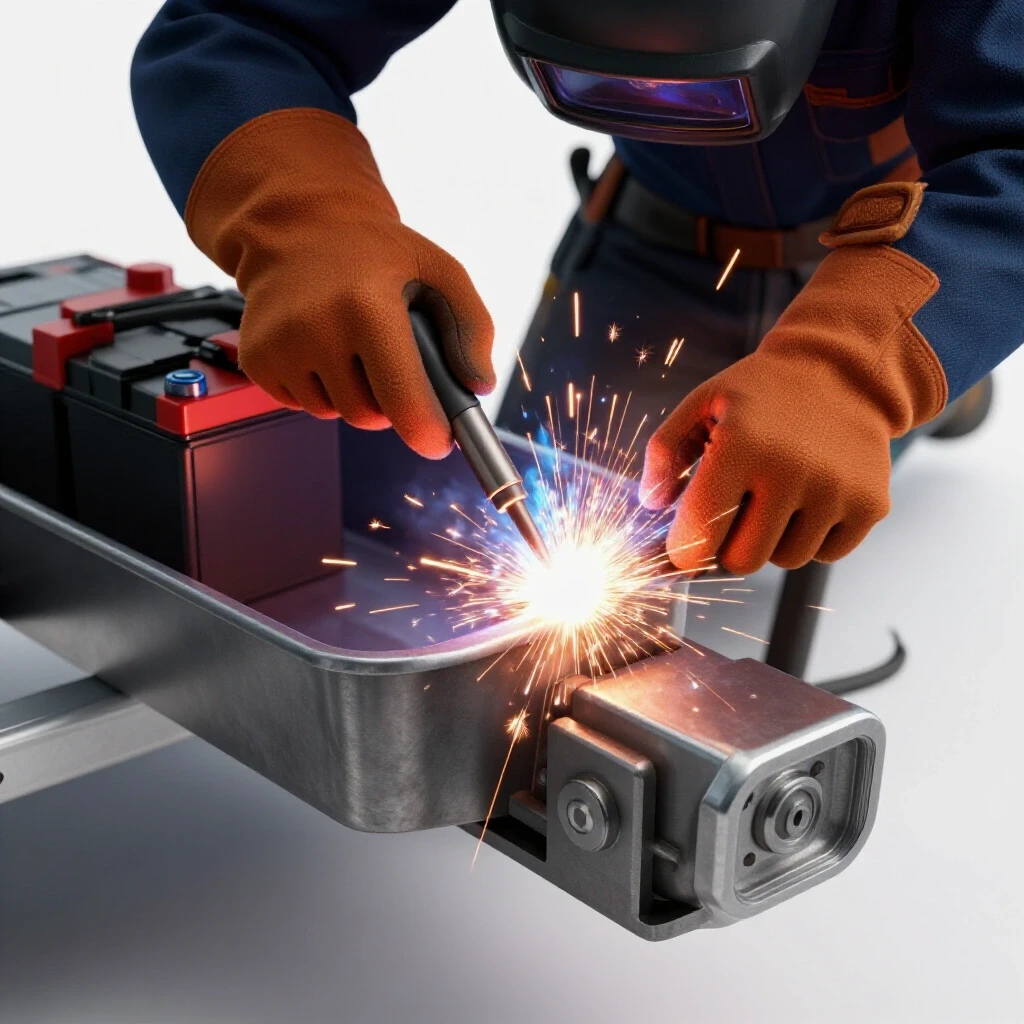
I still remember the first time a project literally moved under my hands. I was building a simple frame for a shop cart, and I had everything clamped down tight. I thought I was being careful, but as the metal cooled, I heard a sharp ping. One of my corner magnets had shifted, and the entire frame had pulled nearly a quarter-inch out of square. It was a frustrating lesson in the physics of heat. When you are fabricating a wall-mounted storage system for heavy automotive components like brake rotors, that kind of error isn’t just an eyesore; it affects how the weight sits on your wall studs and how the rotors slide into their slots.
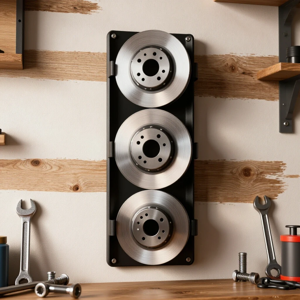
Constructing a vertical steel rack for heavy discs requires more than just sticking metal together. You are dealing with significant cantilevered weight. A single standard rotor can weigh between 15 and 25 pounds. If you plan to store five or six of them, your rack needs to handle over 100 pounds of dead weight pulling away from the wall. In this guide, I will walk you through the process of designing, cutting, and welding a robust storage solution while managing the heat-induced warping that ruins so many garage projects.
Designing the Framework and Calculating Material Allowances
Designing a storage unit for steel discs involves selecting the right profiles to handle shear and tension loads. You must account for the diameter of the rotors and the thickness of the metal to ensure a proper fit. Planning your cut list with precision prevents wasted material and ensures the final assembly remains square during the welding process.
Understanding Kerf and Precision Cutting
Kerf is the width of the material removed by a cutting tool, such as a saw blade or a plasma torch. When you plan your cuts for a vertical storage frame, failing to account for this 1/16th or 1/8th of an inch can result in a rack that is too narrow for the rotors.
I always start by marking my “true” lengths and then adding the kerf width to my total material estimate. If I am using a chop saw with a 1/8-inch abrasive blade, and I need four identical rungs for the rack, I lose half an inch of tubing just to the cuts. This is where many builders fall short, leading to components that are slightly off-dimension.
| Cutting Tool Type | Typical Kerf Width | Accuracy Tolerance |
|---|---|---|
| Cold Saw | 0.090″ – 0.120″ | +/- 0.015″ |
| Abrasive Chop Saw | 0.125″ – 0.150″ | +/- 0.060″ |
| Bandsaw (Portaband) | 0.025″ – 0.045″ | +/- 0.030″ |
| Plasma Cutter (Handheld) | 0.040″ – 0.060″ | +/- 0.080″ |
Selecting Material for High-Load Storage
Material selection for a wall-mounted rack depends on the weight of the items being stored and the desired slimness of the profile. Mild steel is the standard choice for its weldability and strength. Using 1-inch square tubing with a 1/8-inch wall thickness provides a great balance between weight and structural integrity.
Angle iron is another excellent choice for the horizontal “fingers” that hold the rotors. The 90-degree shape provides a natural cradle for the round edge of a brake disc. I typically use 1.5-inch by 1/8-inch angle iron for these components. This thickness ensures the metal won’t deflect or bend downward under the constant pressure of the heavy cast iron discs.
Layout Strategies and Workshop Fixtures
A layout is the roadmap for your fabrication project, involving the precise marking and positioning of metal components before any heat is applied. Using jigs and fixtures helps maintain alignment and ensures that every piece is perpendicular. This stage is critical for preventing the rack from twisting or leaning once it is mounted.
Building Temporary Jigs for Alignment
A workshop jig is a temporary structure or tool used to hold parts in the exact position needed for assembly. For a vertical rack, a simple jig can be made from scrap wood or metal blocks clamped to your welding table. This fixture ensures that the horizontal arms remain perfectly parallel to each other as you work.
When I build these racks, I use a “ladder” jig. I take two long pieces of straight scrap and clamp them to my table at the exact width of the rack. I then place my horizontal rungs between them. This physical restraint is the only way to ensure the arms don’t “fan out” or pull inward. Without a jig, the tension from the cooling welds will almost certainly pull the arms out of alignment by at least 2 or 3 degrees.
Squaring the Main Frame
Ensuring a project is square means that all corners are exactly 90 degrees. For a wall-mounted unit, this is vital because if the frame is “racked” or diamond-shaped, the mounting holes won’t line up with your wall studs. I rely on the 3-4-5 triangle method or a high-quality machinist’s square to check my corners.
- Measure 3 inches on one side.
- Measure 4 inches on the adjacent side.
- The diagonal distance between those two points must be exactly 5 inches.
- Scale this up to 6-8-10 for larger frames to increase accuracy.
Mastering Weld Sequencing to Control Distortion
Weld sequencing is the specific order in which you apply tacks and final beads to a joint to balance the internal stresses caused by heat. As metal melts and cools, it shrinks, pulling the pieces toward the weld. By following a strategic sequence, you can use these pulling forces to your advantage or cancel them out.
The Physics of Angular Weld Shrinkage
When you lay a bead on one side of a joint, the cooling metal acts like a tiny, powerful winch. It pulls the two pieces of steel toward the side where the weld was placed. This is known as angular distortion. In a vertical storage rack, if you weld the top of a horizontal arm first, the arm will pull upward as it cools.
To combat this, I always use a “balanced” welding approach. If I weld the top of a joint, I immediately move to the opposite side or the bottom of that same joint. This distributes the heat and the resulting shrinkage forces more evenly across the material. I expect about 1 to 2 degrees of movement per joint if I am not careful with my sequence.
Effective Tack Welding Techniques
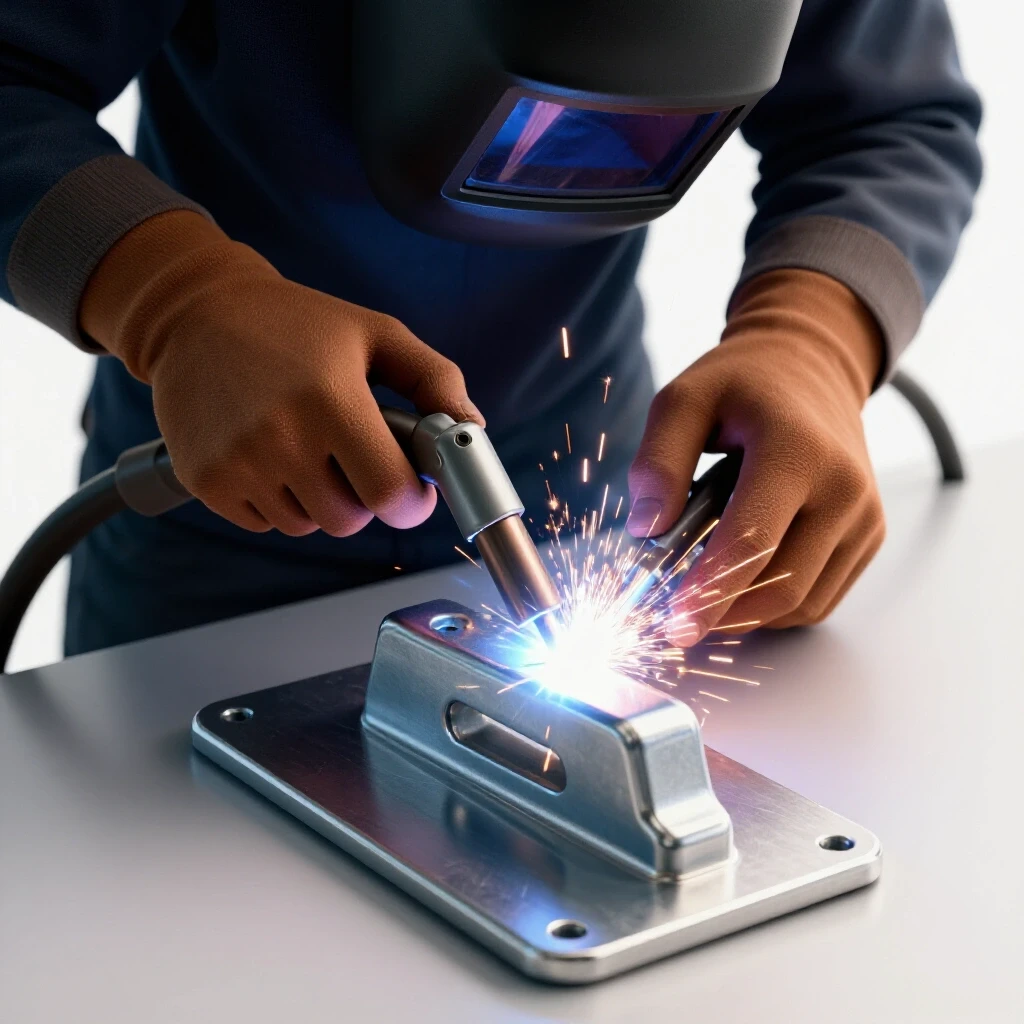
A tack weld is a small, temporary bead used to hold parts in place during the assembly process. Tacks should be strong enough to resist the pull of the main weld but small enough to be easily ground away if a mistake is made. For 1/8-inch wall tubing, a tack about 1/4-inch long is usually sufficient.
I place at least four tacks on every joint before laying a continuous bead. I start with tacks at the corners, diagonally across from each other. This “X” pattern helps lock the joint in place. If you only tack one side, the heat from the second tack will pull the first one out of alignment. Always check for square after your tacks are set but before you start the final passes.
| Joint Type | Recommended Tack Count | Tack Spacing |
|---|---|---|
| Square Tube Butt Joint | 4 (one on each face) | At corners |
| Angle Iron T-Joint | 3 (two on the flange, one on the web) | 1/2″ from edges |
| Flat Bar Lap Joint | 2 (at opposite ends) | 2″ apart |
Executing the Build and Final Assembly
The execution phase is where the planning and layout come together through the actual welding of the components. This involves managing the arc, maintaining the correct travel speed, and following your predetermined weld sequence. Consistency during this stage ensures that every joint has the same strength and visual quality.
Sequencing the Vertical Rungs
When attaching the arms that will hold the rotors, the order of operations is everything. I don’t start at the top and work my way down. Instead, I weld the top rung, then the bottom rung, and then fill in the middle pieces. This “outside-in” sequence helps trap the heat in the center of the frame, which reduces the overall bowing of the vertical rails.
- Tack all horizontal arms into the frame according to your layout marks.
- Check the distance between arms at both the base and the tips to ensure they are parallel within +/- 1/16th of an inch.
- Weld the top-most arm on the left side.
- Weld the bottom-most arm on the right side.
- Continue alternating sides and positions to keep the heat input localized and balanced.
Managing Heat Input
The amount of heat you put into the metal is directly proportional to how much it will warp. I prefer to use a “stitch” welding technique for these storage racks. Instead of running one long, hot bead around the entire joint, I weld in short bursts. This allows the metal to dissipate heat more effectively.
If the metal starts to glow a deep cherry red for more than a second after the arc stops, you are putting too much heat into the part. I often keep a wet rag or a copper heat sink nearby. Placing a thick piece of copper behind the weld area can help pull heat away from the thin-walled tubing, reducing the risk of burn-through and distortion.
Structural Mounting and Wall Anchoring
Mounting a heavy steel rack to a wall requires an understanding of shear strength and fastener ratings. The rack must be securely attached to the structural members of the building, typically wooden or steel studs. Proper anchoring ensures that the weight of the rotors doesn’t pull the rack off the wall or damage the mounting surface.
Calculating Load Paths
The weight of the rotors creates a “lever” effect on your wall anchors. The further the rotors sit away from the wall, the more force is exerted on the top mounting bolts. This is called tension. The bottom bolts primarily handle the “shear” or downward force.
For a rack holding 100 pounds, I use 5/16-inch or 3/8-inch lag bolts. These bolts must penetrate at least 2 inches into the center of the wall studs. I never rely on drywall anchors or “butterfly” toggles for a project this heavy. I always pre-drill my holes to prevent the wood studs from splitting, which would drastically reduce their holding power.
Post-Weld Straightening and Finishing
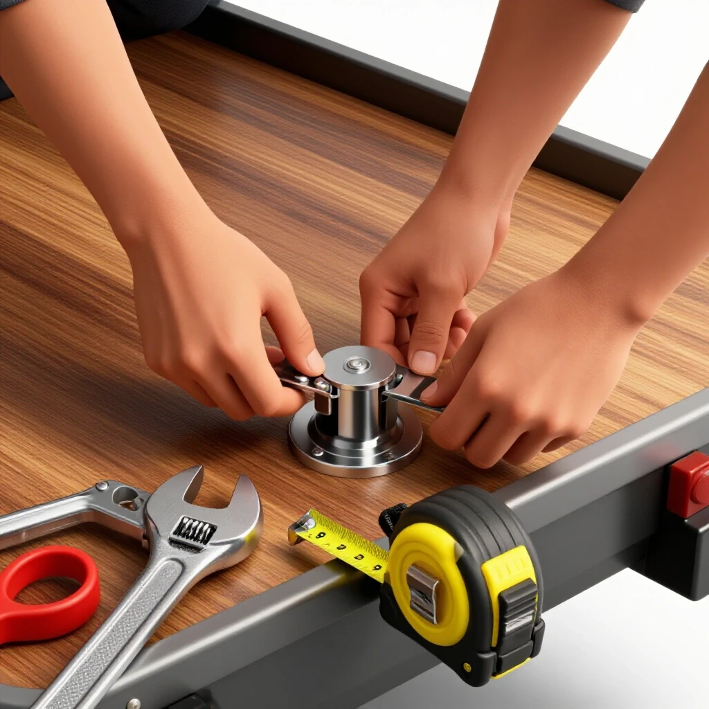
Even with the best sequencing, some minor warping is inevitable. Once the rack has cooled completely, I check it against a flat surface. If there is a slight bow, I use a large adjustable wrench or a dedicated “straightening fork” to gently leverage the metal back into alignment. This is easier to do before you apply any paint or protective coatings.
After straightening, I grind the welds smooth with a 40-grit flap disc followed by an 80-grit disc for a cleaner finish. This removes any sharp spatter that could scratch the rotors. A coat of self-etching primer and a durable topcoat will prevent the mild steel from rusting in a humid garage environment.
Summary Checklist for a Successful Build
- Account for Kerf: Add 1/8-inch to every cut length to ensure the rack isn’t undersized.
- Use a Fixture: Clamp your pieces to a flat table or use a temporary jig to maintain 90-degree angles.
- Tack Diagonally: Place at least four tacks per joint in an alternating pattern.
- Sequence Welds: Start from the outside rungs and work toward the middle to balance shrinkage.
- Control Heat: Use stitch welds and allow the metal to cool between passes to prevent bowing.
- Anchor Securely: Use lag bolts driven into structural studs; avoid mounting to drywall alone.
- Check Tolerances: Aim for a dimensional accuracy of +/- 1/16th of an inch across the entire frame.
Building a storage solution for heavy shop items is a great way to practice precision fabrication. By focusing on layout accuracy and heat management, you create a tool that is both functional and structurally sound. The key is to respect the metal’s tendency to move and to use smart sequencing to keep it in line.
Frequently Asked Questions
Why does my frame twist even when I use magnets?
Magnets are helpful for initial positioning, but they are not strong enough to resist the forces of weld shrinkage. As the weld cools, it exerts hundreds of pounds of force. You must use mechanical clamps or a dedicated fixture table to keep the metal from twisting during the cooling phase.
What is the best thickness for a rotor storage rack?
For most DIY shop applications, 1/8-inch (11-gauge) mild steel is the “sweet spot.” It is thick enough to weld easily without burning through, yet strong enough to support several hundred pounds when properly designed. Using 1/4-inch material is often overkill and adds unnecessary weight to the wall.
How do I know if my welds are strong enough for the weight?
A good weld should have proper penetration, meaning the two pieces of metal have fused into a single structure. For a 1/8-inch thick joint, your weld bead should be roughly the same width as the metal thickness. If you see a consistent “stack of dimes” appearance with no visible gaps or cracks, the joint will likely exceed the strength of the steel itself.
Can I build this rack using a 110v welder?
Yes, a 110v MIG or flux-core welder is perfectly capable of joining 1/8-inch steel. However, you must ensure you are plugged into a dedicated circuit and that your wire feed speed and voltage are set correctly. I recommend doing a few test welds on scrap material and trying to break them with a sledgehammer to verify penetration.
How do I prevent the horizontal arms from sagging over time?
Sagging is usually caused by using metal that is too thin or by poor weld penetration at the joint. By using 1.5-inch angle iron and ensuring a full-perimeter weld where the arm meets the vertical frame, you create a rigid cantilever that can handle the weight of cast iron rotors without permanent deformation.
Should I weld the rack while it is mounted on the wall?
Never weld a project while it is attached to a wall, especially if the wall contains wood studs or electrical wiring. Always perform all welding on a dedicated, fire-safe workbench. Only move the project to the wall for final fitment and anchoring after it has completely cooled and been finished.
What happens if I miss a stud while mounting?
If you miss a stud, the lag bolt will have almost no holding power. You must use a stud finder or the “tap” method to locate the exact center of the 1.5-inch wide wood member. If the rack’s mounting holes don’t align with your stud spacing (usually 16 inches apart), weld a horizontal flat bar across the back of the rack to act as a mounting plate.
How do I stop the metal from rusting?
Mild steel will begin to oxidize (rust) almost immediately if exposed to moisture. After welding and grinding, wipe the metal down with a degreaser or acetone to remove oils. Apply a high-quality primer followed by an enamel paint. This creates a barrier that protects the steel from the elements and the chemicals often found on automotive parts.
Is it better to use square tubing or round tubing?
Square tubing is generally better for beginners because it is much easier to measure, cut, and square up. Round tubing requires “notching” or “coping” the ends to fit against other tubes, which requires specialized tools or complex templates. Square tubing provides flat surfaces for easier clamping and mounting.
How much weight can a single 5/16-inch lag bolt hold?
In a standard spruce or pine stud, a 5/16-inch lag bolt with 2 inches of thread engagement can have a shear strength of several hundred pounds. However, the “pull-out” or tension strength is lower. By using at least four bolts (two at the top and two at the bottom), you distribute the load safely across multiple points.
(This article was written by one of our staff writers, Robert Kline. Visit our Meet the Team page to learn more about the author and their expertise.)