How to Build a Vibration Dampening Compressor Shelf (Guide)
There is a specific kind of frustration that only a fabricator understands. You spend three hours measuring, cutting, and cleaning your steel. You clamp everything down on the bench, verify it is square, and lay your first bead. Then, as the metal cools, you hear that dreaded “tink” sound. You check your square again, and your frame has pulled out by an eighth of an inch. When I first started building shop fixtures thirteen years ago, I ignored these small shifts. I figured a little bit of a twist wouldn’t matter for a simple wall-mounted platform. I was wrong.
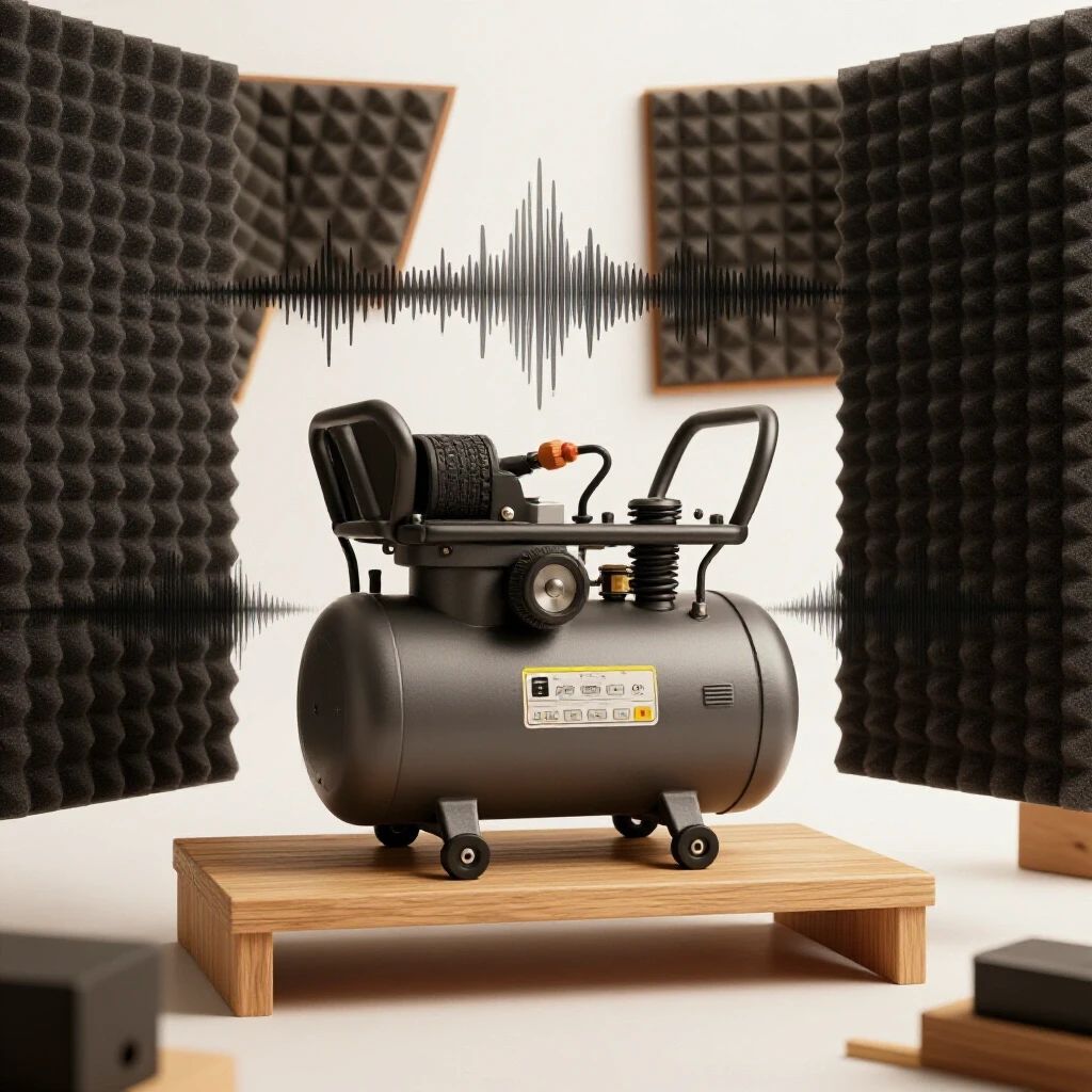
My first attempt at a heavy-duty motor support ended up vibrating so violently it rattled the tools off my workbench. The frame wasn’t flat, so the motor sat unevenly, and the weld distortion had created a “spring” effect that amplified every stroke of the piston. It was a loud, shaky lesson in the importance of layout geometry and heat management. Today, I approach every custom fabrication project with a plan to fight that thermal pull. Building a stable, quiet platform for shop equipment requires more than just sticking metal together; it requires a strategy for controlling the energy of the machine and the heat of the torch.
Designing a Rigid Foundation for Heavy Equipment
A rigid foundation is the backbone of any project meant to support moving machinery. It involves selecting steel profiles that resist twisting and designing a layout that distributes weight evenly across the mounting points. For a project like this, I typically look at 1.5-inch or 2-inch angle iron or square tubing with a 1/8-inch wall thickness to provide the necessary mass.
When I plan these builds, I start with a detailed cut list. You cannot build a square project with “close enough” cuts. If one side of your frame is 1/16 of an inch longer than the other, your welds will have to fill a gap, which increases heat and leads to more warping. I use a dedicated layout table and a high-quality square to verify every piece before the welder even gets plugged in.
Calculating Kerf and Cutting Allowances
Kerf is the width of the material removed by your cutting tool during the fabrication process. If you are using an abrasive chop saw, your kerf might be 3/32 or 1/8 of an inch, whereas a bandsaw might only take 0.035 inches. Failing to account for this means your final assembly will be shorter than your blueprints intend.
| Cutting Tool | Typical Kerf Width | Accuracy Level |
|---|---|---|
| Abrasive Chop Saw | 0.090″ – 0.125″ | Moderate |
| Cold Saw | 0.060″ – 0.080″ | High |
| Horizontal Bandsaw | 0.035″ – 0.045″ | High |
| Plasma Cutter (Handheld) | 0.150″ – 0.200″ | Low |
For a standard 24-inch by 24-inch frame, I mark my steel and then cut on the “waste” side of the line. This ensures the finished piece is exactly the length I need. If I am building a series of supports, I will often clamp a stop-block to my saw table. This allows me to repeat the same cut ten times with a tolerance of +/- 1/32 of an inch, which is vital for keeping the assembly square.
Mastering Workshop Jigs and Fixtures
A workshop jig is a temporary structure used to hold workpieces in the exact position required for assembly. In my shop, I rarely weld “in the air.” Instead, I use the flat surface of a heavy steel table and a series of blocks to lock the parts into a 90-degree relationship before I ever strike an arc.
If you don’t have a professional welding table, you can build a temporary fixture using scrap angle iron. By clamping your project pieces to a known straight edge, you prevent the initial tack welds from pulling the metal out of alignment. I have found that spending 45 minutes on a jig saves me three hours of grinding and “persuading” the metal back into shape later.
Squaring the Frame with the 3-4-5 Method
The 3-4-5 method is a geometric rule used to ensure a corner is exactly 90 degrees by measuring the hypotenuse of a triangle. If you measure 3 inches from a corner on one side and 4 inches on the other, the diagonal distance between those two points must be exactly 5 inches. For larger shop projects, I scale this up to 12, 16, and 20 inches to increase my accuracy.
In custom fabrication projects, I use this method after my first round of tacks. Even with clamps, the heat of a tack weld can pull a corner. By checking the diagonals of the entire frame, I can see if the structure is “racked” or leaning to one side. If the two diagonal measurements across the frame are within 1/16 of an inch of each other, the assembly is square enough for final welding.
Controlling Metal Warping with Strategic Tacking
Metal warping is the permanent distortion of a part caused by the uneven heating and cooling during the welding process. As the weld pool cools, it shrinks, pulling the surrounding base metal toward the center of the bead. This force is powerful enough to bend thick steel plates if they are not properly restrained.
To combat this, I use a specific tacking sequence. A tack weld should be small enough to be easily ground out if you make a mistake, but strong enough to resist the initial cooling forces. For 1/8-inch steel, I usually place a 1/4-inch tack on every corner, starting on the inside of the joint and then moving to the outside.
The Importance of Tack Weld Sizing and Spacing
Tack welds act as tiny structural anchors that hold your dimensions while you apply the final beads. If your tacks are too small, they will crack as the main weld puts stress on the joint. If they are too large, they create “humps” in your final weld that look unprofessional and can hide lack of penetration.
- Clean the joint: Remove all mill scale and oil within one inch of the weld area.
- Clamp the work: Use C-clamps or F-clamps to press the metal flat against your jig.
- Place the first tack: Start at the most critical corner to lock the dimensions.
- Check for square: Re-measure your diagonals after the first two tacks.
- Opposite corner tacking: Move to the diagonally opposite corner to balance the heat.
- Final tacking: Place tacks every 3 to 4 inches on longer spans to prevent the “smiling” effect where the middle of a tube bows upward.
Executing a Balanced Weld Sequencing Layout
A weld sequencing layout is the specific order in which you apply beads to a project to minimize overall distortion. Instead of welding one entire corner and moving to the next, you “jump” around the project to distribute the heat input evenly across the frame. This prevents one side of the assembly from getting significantly hotter than the other.
When I built a heavy-duty wall rack for my old twin-cylinder pump, I learned that welding in a circle is a recipe for a twisted frame. Now, I use a “back-stepping” or “star” pattern. If I weld two inches on the front-left corner, my next weld will be on the back-right corner. This keeps the thermal expansion balanced.
Managing Heat Input and Cooling Rates
The faster you put heat into the metal, the more it wants to move. However, if you weld too slowly, the heat soaks into the surrounding area and causes widespread warping. The goal is to find a balance where you get deep penetration without turning the entire piece of steel cherry red.
- Weld in short bursts: Limit your beads to 2 or 3 inches at a time.
- Allow for cooling: If the steel is too hot to touch with a gloved hand, wait five minutes before the next pass.
- Use heat sinks: Clamping a thick piece of copper or aluminum behind the weld can help pull heat away from the steel.
- Vary your direction: If you weld the first joint from left to right, weld the matching joint on the other side from right to left to counteract the pull.
| Welding Sequence Type | Best Use Case | Distortion Control Level |
|---|---|---|
| Continuous Bead | Short joints under 2″ | Low |
| Back-stepping | Long structural seams | High |
| Skip Welding | Thin-walled tubing | Very High |
| Symmetrical Tacking | Initial frame assembly | Essential |
Integrating Vibration Isolation Components
Vibration isolation is the process of decoupling a machine from its support structure to prevent the transfer of energy. In a shop environment, this usually involves placing elastomer mounts or rubber pads between the equipment feet and the steel shelf. This “breaks” the path that sound and movement travel through.
When I select isolators for a custom fabrication project, I look at the “durometer” or hardness of the rubber. If the rubber is too hard, it acts like a solid block and transfers all the vibration. If it is too soft, the machine will wobble and potentially stress the air lines or mounting bolts. For most mid-sized shop tools, a 40 to 60 durometer rubber is the sweet spot.
Selecting the Right Dampening Materials
Not all rubber is created equal. I have tried using old pieces of tire or conveyor belt, but they rarely provide the consistent dampening needed for a high-frequency vibration. Dedicated vibration pads are often made of a sandwich of cork and rubber or specialized neoprene.
- Isolator Studs: These are threaded bolts embedded in rubber. They allow you to bolt the machine to the rubber and the rubber to the shelf with no metal-to-metal contact.
- Grommet Mounts: These fit into a hole in your steel frame. The bolt passes through a rubber sleeve, ensuring the bolt head never touches the steel.
- Waffle Pads: These are thick mats placed under the entire base. They are great for heavy equipment but can shift over time if not restrained.
Ensuring Accuracy in Mounting and Final Alignment
Final alignment is the process of verifying that the finished project is level, plumb, and ready to accept the load. Even a perfectly welded shelf can fail if it is mounted to a wall that isn’t straight or if the mounting anchors are not rated for the weight and vibration.
I always use a laser level or a high-quality spirit level when marking the wall for my support brackets. If the shelf is slightly tilted, the oil in the machine’s pump may not sit at the correct level, leading to premature wear. Furthermore, I use Grade 5 or Grade 8 bolts for all structural connections. Standard “big box” hardware store bolts are often too soft and can shear under the constant “micro-hammering” of a vibrating motor.
Anchor Selection and Wall Loading
When mounting a heavy steel platform to a shop wall, you must consider the “pull-out” force. A 100-pound machine sitting on a 20-inch shelf exerts significantly more than 100 pounds of force on the top mounting bolts due to leverage.
- Locate Studs: Never mount a heavy vibrating load into drywall or thin siding alone. Use a stud finder to locate the center of the framing members.
- Pilot Holes: Drill pilot holes for your lag bolts to prevent splitting the wood. A split stud has almost no holding power.
- Washer Usage: Use thick fender washers to spread the load across the surface of the steel frame.
- Verification: Once mounted, grab the shelf and give it a firm shake. If you see the wall move, you need to add diagonal bracing down to a lower point on the wall.
Common Pitfalls in Custom Shop Builds
In my thirteen years of fabrication, I have made every mistake in the book. The most common error I see with newer builders is “over-welding.” There is a temptation to run a bead along every single inch of a joint. Not only is this unnecessary for the loads we see in a home shop, but it also guarantees that the project will warp.
Another mistake is ignoring the “gap.” If your pieces don’t fit tightly, you will be tempted to turn up the heat to bridge the gap. This extra heat is the enemy of a straight project. I always aim for a “light-tight” fit on my joints before I start the welder.
- Inaccurate Layouts: Measuring from the wrong end of the tape measure or forgetting to account for the thickness of the steel.
- Poor Grounding: A weak ground clamp causes an unstable arc, leading to “cold” welds that look okay but have no strength.
- Rushing the Cooling: Using water to cool a weld can make the steel brittle and cause it to crack under vibration.
- Ignoring the Torque: Failing to tighten mounting bolts to the proper specification, allowing the machine to “walk” across the shelf.
Final Review and Maintenance
Once the project is complete, I perform a “first run” test. I start the machine and place my hand on the wall next to the shelf. If I can feel the vibration in the wall, I know I need to adjust my dampeners or add more mass to the frame. Sometimes, simply adding a 1/4-inch steel plate to the top of the shelf provides the weight needed to “tame” the high-frequency shakes.
Check your mounting bolts after the first 10 hours of use. Vibration has a way of finding loose threads. I often use blue thread-locking compound on the bolts that hold the isolators in place. This provides peace of mind that the constant movement won’t vibrate the nuts right off the studs.
Frequently Asked Questions
Why does my frame always twist into a “diamond” shape? This usually happens because you are welding all the outside corners first. The shrinkage pulls the corners inward. To fix this, use the 3-4-5 method to square the frame and place heavy tacks on the inside corners first, then check square again before moving to the outside.
Can I use wood for a vibration-dampening shelf? While wood naturally dampens some vibration, it lacks the mass and rigidity of steel. Over time, the vibration will loosen the screws or nails in a wooden frame. Steel is a better choice for long-term durability and safety when supporting heavy, moving parts.
How thick should the rubber dampeners be? For most garage equipment, a thickness of 1/2 inch to 3/4 inch is ideal. If the rubber is too thin, it will “bottom out” under the weight. If it is too thick, the machine may become unstable and tip during start-up.
What is the best way to cut square tubing for a frame? A horizontal bandsaw is the gold standard for accuracy. If you only have a grinder with a cut-off wheel, use a “wrap-around” template (like a piece of straight-edged paper) to mark all four sides of the tube. This ensures your cut stays square as you work your way around the piece.
Do I need to weld both sides of the angle iron? For a shelf carrying 100-200 pounds, a solid weld on the outside and a couple of 1-inch “stitch” welds on the inside are usually sufficient. Welding every single surface often adds more heat than is necessary for the structural load.
How do I prevent the shelf from “ringing” like a bell? This is caused by the resonance of the steel. You can stop this by “deadening” the metal. Gluing a piece of heavy rubber matting or even a piece of plywood to the underside of the main platform will shift the resonant frequency and stop the noise.
Should I paint the steel before or after assembly? Always weld on bare, clean steel. You can prime and paint the assembly after all the welding is done and the metal has cooled. Just be sure to wipe it down with acetone or a degreaser first to remove any oils or fingerprints.
What size lag bolts should I use for wall mounting? I recommend at least 3/8-inch diameter lag bolts that penetrate the wall studs by at least 2.5 inches. For a four-bolt mounting pattern, this provides a massive amount of shear strength and pull-out resistance.
Is it better to bolt or weld the main frame? Welding creates a more rigid, one-piece structure that won’t loosen over time. However, bolting allows you to disassemble or adjust the shelf later. For a vibration-prone project, a welded frame is generally superior because there are no bolts to rattle loose.
How do I know if my welds are strong enough? A good weld should have a consistent ripple pattern and should “wet into” both pieces of metal without leaving a sharp undercut or a rounded “cold” edge. If you see a smooth transition between the bead and the base metal, you likely have good fusion.
Can I use a regular rubber mat instead of isolator mounts? A mat is better than nothing, but it doesn’t “decouple” the bolt. The vibration will travel through the mounting bolt, into the shelf, and into the wall. True isolator mounts use rubber to separate the bolt from the frame entirely.
What happens if I don’t account for kerf? If you have four pieces of tubing and you lose 1/8-inch on every cut, your final frame could be 1/2-inch smaller than you planned. This might not seem like much, but it can mean your equipment feet no longer line up with the mounting holes you drilled.
(This article was written by one of our staff writers, Robert Kline. Visit our Meet the Team page to learn more about the author and their expertise.)