How to Inspect and Repair Cracked Steel Welds Safely (Fix)
I remember standing over a custom-built engine stand about twelve years ago, watching a hairline fracture creep across a gusset I had welded just months prior. It was frustrating because I thought I had done everything right—the beads looked clean, the penetration seemed deep, and the steel was prepped. That moment taught me that a weld failing isn’t just a mistake; it is a diagnostic data point that tells a story about stress, heat, and technique.
In my eighteen years as a millwright and diagnostic specialist, I have learned that the most dangerous thing in a shop isn’t a broken tool—it is a tool you think is fixed but isn’t. When a steel joint gives way, your first instinct might be to just run another bead over the top. That is a mistake that leads to “stacking” failures. Instead, we need to approach a fractured joint the same way we approach a noisy spindle or a motor controller fault: by isolating the variables and finding the root cause before we ever pick up the torch.
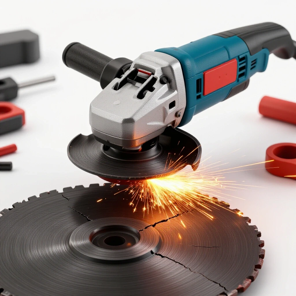
This guide is for the fabricator who is tired of guesswork. We are going to look at how to systematically find, analyze, and remediate failures in steel projects. We will focus on the shop-level tools you already have, like angle grinders and MIG or TIG setups, to ensure your repairs are as solid as the original material.
The Systematic Framework for Weld Failure Diagnostics
This framework involves a three-step process: observation, isolation, and variable control to ensure you aren’t just treating a symptom. By mapping the failure, you can determine if the issue was metallurgical, such as hydrogen embrittlement, or mechanical, such as excessive vibrational stress from a nearby motor.
Before you touch a grinder, you have to be a detective. I start every repair by asking: “Why did this fail today and not yesterday?” If a weld on a lathe stand cracks, I don’t just look at the metal; I check the leveling feet. If the machine has a 0.005-inch wobble, that vibration is a hammer hitting your weld thousands of times an hour.
To isolate the problem, I use a diagnostic log. I record the material thickness, the original welding process used, and the environment the part lived in. Was it near a door where cold drafts could cause rapid cooling? Was it subject to “tool chatter” that sent high-frequency harmonics through the frame? Identifying these variables prevents you from making the same mistake twice.
- Observation: Look for the “start” and “stop” points of the crack.
- Isolation: Determine if the crack is in the weld metal itself or the heat-affected zone (HAZ).
- Variable Control: Check for external factors like machine misalignment or improper shielding gas flow.
Visual and Chemical Methods for Spotting Surface Fractures
Detecting failures in steel requires a combination of high-intensity lighting, magnification, and simple chemical indicators to reveal what the naked eye might miss. These methods allow a fabricator to see the true extent of a fracture, ensuring that a repair covers the entire damaged area rather than just the visible center.
Sometimes a crack is obvious, but often it is a “spiderweb” of tiny lines hidden under mill scale or paint. I always start with a stiff wire brush or a flap disc to get down to shiny metal. Once the area is clean, I use a basic dye penetrant kit. This is a three-step chemical process: a cleaner, a bright red dye, and a white developer.
When you spray the developer over the dye, the red liquid is pulled out of the crack by capillary action. It creates a bright red line on a white background, showing you exactly where the crack ends. This is critical because a crack often extends 1/4 inch to 1/2 inch further than you think it does. If you don’t find the “toes” of the crack, the fracture will simply continue to grow under your new weld.
- Cleaning: Remove all paint, oil, and rust within 2 inches of the failure.
- Dye Application: Let the penetrant sit for at least 10 minutes to soak into the fracture.
- Developer: Apply in thin coats; the red “bleed” will indicate the crack’s path.
Why Steel Bonds Fail: Root Cause Analysis
Understanding the root cause of a fracture involves analyzing the relationship between heat input, cooling rates, and mechanical load. Most shop-level failures stem from either “cold lap,” where the weld sits on top of the metal without fusing, or “stress risers” caused by sharp corners and poor joint design.
In my experience, many cracks in intermediate shops come from “hot cracking” or “cold cracking.” Hot cracking happens as the weld is solidifying, often because the bead was too thin or the cooling was too fast. Cold cracking, or delayed cracking, can happen days after the weld is finished, often due to hydrogen being trapped in the weld pool.
I once worked on a large belt sander frame that kept cracking at the motor mount. After checking the alignment, I realized the welder had been using a shielding gas flow rate that was too low—only about 10 CFH. This caused atmospheric contamination, leading to porosity. Porosity acts like a perforated line on a piece of paper; it makes the metal easy to tear. By bumping the gas to 25 CFH and cleaning the base metal better, the cracking stopped.
| Defect Type | Likely Cause | Diagnostic Sign |
|---|---|---|
| Longitudinal Crack | High travel speed / narrow bead | Crack runs down the center of the bead |
| Toe Crack | Excessive heat / undercut | Crack at the edge where weld meets base metal |
| Porosity | Gas coverage / dirty metal | Tiny “pinholes” or “Swiss cheese” appearance |
| Cold Lap | Low voltage / poor technique | Weld looks like it is “dripping” onto the plate |
Preparing the Joint for a Clean Remediation
Proper preparation for a repair involves more than just cleaning; it requires “veeing” out the crack to ensure full penetration and using “stop-drilling” to halt crack propagation. This stage is where the actual fix is won or lost, as it creates the foundation for the new metallurgical bond.
The biggest mistake I see is “capping.” This is when a fabricator just welds a new bead over a crack. The crack is still there, acting as a wedge that will eventually split the new weld. To do this right, you must use a grinding wheel to create a V-groove along the entire length of the crack. You want to grind deep enough to reach the bottom of the fracture.
Another professional trick I use is “stop-drilling.” I take a small drill bit—usually 1/8 inch—and drill a hole exactly at each end of the crack. This rounds out the sharp tip of the fracture, which is a major stress riser. By turning a sharp point into a circle, you dissipate the stress and prevent the crack from traveling further while you are working.
- Identify the ends of the crack using dye or magnification.
- Drill 1/8-inch holes at both ends of the fracture.
- Grind a 60-to-90-degree V-groove between the holes.
- Remove all burrs and debris with a dedicated stainless steel wire brush.
Executing the Repair with Precision
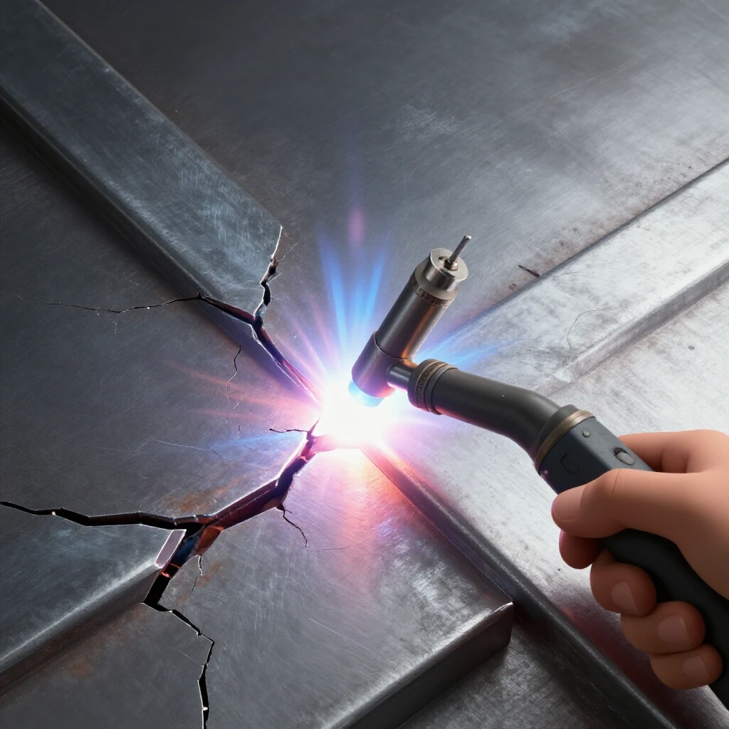
Rewelding a failed joint requires a different approach than the original weld, often involving a “multi-pass” technique to manage heat and ensure a deep bond. This step focuses on controlling the weld puddle to avoid the same stresses that caused the initial failure, such as excessive shrinkage or lack of fusion.
When I start the actual repair, I prefer a “stringer bead” over a “weave” pattern. Weaving can put too much heat into the metal, which enlarges the heat-affected zone and makes the surrounding steel brittle. I start my arc in one of the stop-drilled holes, fill it, and then move steadily along the V-groove.
If the metal is thicker than 1/4 inch, I use multiple passes. The first pass, or “root pass,” should be done with slightly higher voltage to ensure it bites into the bottom of the groove. The subsequent “filler passes” build the strength back up. I always allow the metal to cool enough that I can touch it with a gloved hand between passes. This prevents the “grain growth” in the steel that leads to future brittleness.
- Amperage/Voltage: Set 10% higher than normal for the root pass to ensure penetration.
- Travel Speed: Maintain a consistent “push” or “pull” angle of 10-15 degrees.
- Interpass Cleaning: Use a wire brush between every bead to remove silica or slag.
Managing Machine Vibration and Tool Chatter
Mechanical vibrations and tool chatter are often the “silent killers” of steel welds, as they introduce cyclic loading that fatigues the metal over time. Identifying these harmonic issues involves checking for spindle backlash, motor mount stability, and the overall rigidity of the fabrication.
If you are repairing a weld on a piece of machinery, like a mill or a lathe, you have to look at the “harmonics.” I’ve seen welds on tool rests crack because the operator was dealing with excessive tool chatter. Chatter isn’t just a bad finish on your part; it is a high-frequency vibration that can reach thousands of cycles per second.
Check your machine’s backlash. If your lead screws have more than 0.003 or 0.005 inches of play, the “slap” of the table can create impact loads on the frame. I use a dial indicator to measure this play. If the machine isn’t rigid, no weld—no matter how perfect—will hold up forever. Sometimes the “fix” for a cracked weld is actually tightening a gib or replacing a worn-out bearing.
- Backlash Tolerance: Aim for less than 0.002 inches on precision equipment.
- Spindle Play: Check for radial and axial movement using a 0.0005-inch indicator.
- Damping: Consider adding rubber isolation mounts if the machine vibrates excessively.
Tracking and Documenting the Repair Process
Maintaining a repair log is a vital part of professional diagnostics, as it allows you to track the success of your methods over time. By recording the specific settings, materials, and environmental conditions of a fix, you create a database that helps you solve similar “gremlins” in the future.
I keep a simple notebook in my top toolbox drawer. Every time I have to fix a fractured joint, I write down the date, the machine, the symptoms, and the fix. This is how I discovered that a certain brand of “bargain” welding wire was causing porosity in my shop three years ago. I noticed that every repair I did with that spool ended up cracking again within six months.
Your log should also include measurements. If you are aligning a motor, write down the “before” and “after” shim thickness. If you are fixing a weld, note the gas flow (CFH) and the wire feed speed. This data-driven approach removes the “magic” from the process and replaces it with engineering.
- Date and Machine ID.
- Symptom (e.g., “3-inch crack in motor mount”).
- Root Cause (e.g., “Vibration from worn-out V-belt”).
- Repair Specs (e.g., “60-degree V-groove, 75/25 Gas, 19.5 Volts”).
- Follow-up date (Check the repair in 30 days).
Advanced Diagnostic Tools for the Modern Shop
Modern diagnostic tools, such as infrared thermometers and smartphone-based vibration analyzers, provide precise data that traditional visual inspection cannot. These tools allow a fabricator to monitor heat distribution during a repair and identify specific vibration frequencies that may be causing structural stress.
We live in a great era for troubleshooting. I now use an infrared (IR) thermometer to check for “hot spots” on machines while they are running. If a bearing housing is 40 degrees hotter than the rest of the machine, that heat is transferring to the frame, causing thermal expansion that can stress your welds.
I also use vibration analysis apps on my phone. By resting the phone on a machine frame, I can see a graph of the vibration frequencies. If I see a huge spike at 60Hz, I know I have an electrical or motor balance issue. If the spike is at a much higher frequency, it’s likely tool chatter or a failing bearing. Addressing these “invisible” forces is the key to a permanent repair.
- IR Thermometer: Monitor interpass temperatures to stay within the 300-500°F range for mild steel.
- Vibration App: Identify resonant frequencies that might be fatiguing the metal.
- Digital Calipers: Measure material thickness accurately to set your welder’s parameters.
Common Pitfalls in Steel Remediation
Avoiding common errors, such as “slugging” a joint or ignoring the heat-affected zone, is essential for maintaining the integrity of a repaired part. These mistakes often stem from a desire to finish the job quickly, but they usually result in a failure that is more difficult to fix the second time.
One of the biggest mistakes I see is “slugging.” This is when someone drops a piece of scrap metal or a bolt into a large gap and welds over it. This creates a massive internal stress point and almost guarantees a future crack. If the gap is too large, you need to build up the edges with “buttering” passes before joining them.
Another pitfall is ignoring the “toe” of the weld. The toe is where the weld face meets the base metal. If there is a sharp undercut there—a little “valley” where the metal was eaten away—that is where the next crack will start. Always ensure your weld profile is smooth and blends into the base metal. If it doesn’t, a light sanding with a flap disc to smooth the transition can save the joint.
- Slugging: Never use “filler” chunks; build the joint with weld metal.
- Undercutting: Watch your work angle to ensure the puddle fills the edges.
- Over-welding: More is not always better; a massive bead can cause more distortion.
Troubleshooting Weld Porosity and Contamination
Porosity is a frequent contributor to weld failure, appearing as small voids that weaken the structural integrity of the steel. Identifying the source of porosity—whether it be a gas leak, wind interference, or surface contaminants—is a primary step in ensuring a repair doesn’t fail for the same reasons as the original.
If you find “bubbles” in your repair weld, stop immediately. Porosity is usually caused by a loss of shielding gas. I check my regulator first (I usually run 20-25 CFH for MIG). If that’s fine, I check the “O-rings” in the MIG gun. A tiny tear in an O-ring can suck in air, contaminating the weld.
Contamination from oil or paint is the other culprit. Even if the surface looks clean, oil can be trapped in the “pores” of the steel. I use a dedicated degreaser or acetone before welding. If the steel was previously galvanized, you must grind off the zinc coating entirely, or the weld will be brittle and “pop” as you are laying it down.
| Symptom | Checkpoint | Solution |
|---|---|---|
| Surface Pinholes | Shielding gas flow | Increase flow or check for drafts |
| Internal Voids | Surface cleanliness | Grind deeper; use acetone wipe |
| Black Soot | Torch angle | Adjust to a 15-degree “push” angle |
| Brittle Beads | Material type | Ensure you aren’t welding on “unknown” alloy |
Final Verification and Testing the Repair
After a repair is completed, it must be verified through non-destructive testing and functional checks to ensure it can handle the intended workload. This phase involves both a visual critique of the new bead and a “stress test” under controlled conditions to confirm the fix is permanent.
Once the weld has cooled naturally—never quench a repair with water, as it makes the steel brittle—I do a final visual inspection. I’m looking for a consistent ripple pattern and a smooth transition to the base metal. If the part is non-critical, like a shop cart or a tool stand, I’ll give it a “ring test.” Striking the metal with a small hammer should produce a clear, sustaining ring. A dull “thud” often indicates an internal void or a crack that wasn’t fully removed.
Finally, I put the part back into service but monitor it closely. I check the repair after the first hour of use, then after the first day. If I see any “crazing” or tiny lines appearing in the paint or the metal, I know my root cause analysis missed something, and I go back to the diagnostic log to find the missing variable.
- Visual: No undercut, no overlap, consistent width.
- Ring Test: Listen for a clear harmonic resonance.
- Operational Check: Monitor for heat or vibration at the repair site.
Frequently Asked Questions
How do I know if a crack is too big to repair? In a hobbyist or intermediate shop setting, if the crack has caused the base metal to warp or “potato chip” significantly, the structural integrity of the entire part may be compromised. If the crack has traveled through more than 50% of a critical joint, it is often safer to cut the entire section out and replace it with new steel rather than trying to “patch” the fracture.
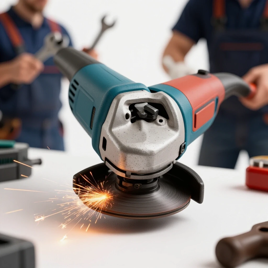
Can I use a regular 4.5-inch angle grinder for all my prep work? Yes, a standard angle grinder is the workhorse of repair. Use a hard grinding wheel for “veeing” out the crack and a 40-grit or 60-grit flap disc for cleaning the surface. Avoid using “thin” cutoff wheels for grinding, as they can shatter if put under side-load.
What is the “stop-hole” method exactly? A crack is a concentrated point of stress. By drilling a small hole at the very tip of the crack, you replace that sharp point with a radius. This distributes the stress around the circle, preventing the crack from growing while you are grinding and welding.
Why shouldn’t I cool the weld with water to speed things up? Rapid cooling (quenching) changes the crystalline structure of the steel, often forming “martensite,” which is very hard but extremely brittle. This makes the repair prone to “shattering” under impact. Always let your repairs air-cool.
How do I tell the difference between a crack and a scratch? Use the dye penetrant method. A scratch is shallow and won’t hold enough dye to “bleed” through the developer. A crack has depth and will continue to push dye out, creating a growing red mark on the white developer.
Is it okay to weld over old paint if I’m in a hurry? No. Paint burns and creates gas, which gets trapped in the molten metal, causing porosity. It also creates toxic fumes. Always grind back to bare, shiny metal at least one inch away from the weld zone.
What is “undercut” and why is it bad? Undercut is a groove melted into the base metal at the edge of the weld that isn’t filled by the weld metal. It acts as a “perforation” that makes the metal much weaker at that specific point, often leading to a new crack.
What gas should I use for repairing mild steel with a MIG welder? For most shop repairs, a “C25” mix (75% Argon and 25% CO2) is the best all-around choice. It provides a stable arc and good penetration with minimal splatter.
How deep should I grind the V-groove? You should grind until you can no longer see the line of the crack at the bottom of the groove. If the metal is 1/4 inch thick, you should be grinding at least 3/16 of an inch deep, or even all the way through if you can use a backing bar.
What if the crack is in a corner that I can’t get a grinder into? In tight spots, you can use a die grinder with a carbide burr bit. These are excellent for “carving” out cracks in corners or inside tubes where a large grinding wheel won’t fit.
Does it matter what direction I weld in? For repairs, “dragging” the torch (pulling) often provides deeper penetration, while “pushing” provides a flatter bead and better visibility. For structural repairs on thicker steel, a slight “drag” is usually preferred to ensure the root is solid.
How can I tell if my machine vibration is what caused the crack? If the crack is located near a motor mount or a bearing housing, and you can feel a “numbing” vibration when you touch the frame, the vibration is likely the culprit. Use a vibration-damping mat or check for unbalanced pulleys.
(This article was written by one of our staff writers, Paul Whitaker. Visit our Meet the Team page to learn more about the author and their expertise.)