How to Install Threaded Rivet Nuts in Thin Tubing (Tutorial)
In my eighteen years navigating the floors of industrial fabrication mills, I have learned that the most frustrating problems are often the ones you cannot see. I remember a specific contract involving a high-frequency vibration sensor housing for a local power plant. We were working with thin-walled stainless steel tubing that had to remain structurally sound without the heat distortion of traditional joining methods. If the internal threads weren’t perfectly seated, the entire sensor array would experience harmonic resonance, leading to tool chatter in the mounting brackets and eventually, a total system failure.
Developing a systematic approach to installing blind threaded fasteners in these thin-walled sections is much like diagnosing electrical gremlins or isolating the root cause of welding porosity. It requires a commitment to mechanical baselines and a refusal to rely on guesswork. When you are dealing with materials that do not offer enough thickness for traditional tapping, you have to rely on mechanical deformation. Understanding the physics behind that deformation is the difference between a secure, permanent mount and a loose component that ruins an expensive assembly.
Establishing the Mechanical Baseline for Blind Threaded Inserts
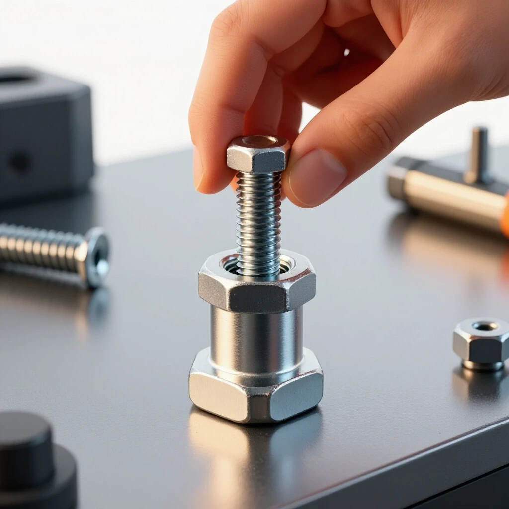
Blind threaded inserts are specialized fasteners designed to provide load-bearing threads in materials too thin to be tapped. They function through a controlled mechanical collapse, where an installation tool pulls a threaded mandrel to deform the unthreaded shank of the insert against the back of the workpiece.
This process creates a secondary flange on the blind side of the material, effectively sandwiching the tubing wall between the original flange and the newly formed bulge. The integrity of this joint depends entirely on the relationship between the hole diameter, the material thickness, and the stroke length of the installation tool. Just as I would check the backlash of 0.002 inches on a lathe carriage to ensure precision, I must verify the grip range of the fastener against the actual wall thickness of the tubing before the first pull.
Precision Hole Preparation and Clearance Standards
Proper installation starts with a hole diameter that provides minimal clearance for the insert body. This ensures the flange sits flush and the expansion occurs uniformly against the internal wall of the tubing. If the hole is even slightly oversized, the insert may spin during the final bolt torquing, a failure that is difficult to rectify once the assembly is closed.
In my experience, using a standard twist drill can sometimes result in an “out-of-round” hole, especially in thin-walled tubing. I prefer using a high-quality step drill or a reamer to achieve a precise diameter. This minimizes the risk of the insert shifting during the deformation phase. The goal is a “slip-fit” where the insert enters the hole with no lateral play but without requiring significant force.
| Insert Thread Size | Recommended Hole Diameter (Inches) | Drill Bit Size (Decimal Equivalent) | Tolerance Range (+/-) |
|---|---|---|---|
| 6-32 | 0.189 | #12 (0.1890) | 0.002 |
| 8-32 | 0.221 | #2 (0.2210) | 0.002 |
| 10-32 | 0.250 | 1/4 (0.2500) | 0.003 |
| 1/4-20 | 0.332 | Q (0.3320) | 0.003 |
| 5/16-18 | 0.413 | 13/32 (0.4063) | 0.004 |
| 3/8-16 | 0.500 | 1/2 (0.5000) | 0.004 |
Calibrating the Installation Tooling for Consistency
Tool calibration involves setting the stroke length or pulling force to match the specific grip range of the fastener. This prevents under-setting, which leads to spinning, or over-setting, which damages the mandrel threads. Much like setting the feed-per-tooth calculations (IPT) on a mill to avoid tool chatter, setting the stroke on a rivet nut tool is about managing the forces applied to the material.
Most professional-grade manual tools use a threaded adjustment sleeve to limit how far the handles can close. To calibrate this, I always use a scrap piece of the exact tubing I am using for the project. I thread the insert onto the mandrel until the head of the insert touches the tool’s nosepiece. I then adjust the stroke so that the handles bottom out exactly when the insert has formed a full, firm bulge on the backside of the scrap piece.
Analyzing Grip Range and Material Thickness
The “grip range” is the specific range of material thickness an insert is designed to accommodate. If you try to use an insert designed for 0.080 to 0.130 inches on a tube with a wall thickness of only 0.040 inches, the fastener will not collapse correctly. The bulge will form too far away from the material, leaving the insert loose.
When I am troubleshooting a fabrication layout, I use digital calipers to measure the wall thickness of the tubing at several points. Tubing can have slight variations in wall thickness due to the manufacturing process, especially near the welded seam. I ensure that the chosen fastener’s grip range sits comfortably in the middle of these measurements. For example, if the wall thickness is 0.065 inches, I choose a fastener with a grip range of 0.020 to 0.080 inches.
Executing the Mechanical Deformation Sequence
The actual installation involves threading the insert onto a mandrel, placing it in the hole, and applying axial force. This force collapses the unthreaded portion of the shank into a “bulge” that locks the fastener in place. The process must be smooth and continuous to ensure the threads inside the insert remain perpendicular to the tubing surface.
- Thread the Insert: Wind the insert onto the tool mandrel until the flange is snug against the nosepiece. Ensure at least 90% of the insert’s threads are engaged with the mandrel to prevent stripping.
- Insert into Workpiece: Place the fastener into the pre-drilled hole. Ensure the tool is held at a perfect 90-degree angle to the tubing surface. Any tilt will cause the insert to set unevenly.
- Actuate the Tool: Squeeze the handles or trigger firmly. You will feel an initial resistance as the shank begins to collapse, followed by a “hard stop” once the bulge is fully formed against the back wall.
- Unthread the Mandrel: Use the tool’s release mechanism or knob to back the mandrel out of the newly installed threads. Avoid pulling the tool away until the mandrel is completely free.
Managing Mechanical Tolerances and Alignment
In complex machinery, such as a custom lathe stand or a motor mount, the alignment of multiple threaded inserts is critical. If one insert is off by 0.010 inches, the mounting bolt will cross-thread or put lateral stress on the assembly. This is similar to how a spindle backlash issue can ruin a precision bore.
To maintain alignment, I often use a transfer punch to mark hole locations through the mounting bracket itself. Once the holes are drilled, I install the inserts one by one, checking the alignment of the bracket after each installation. This systematic verification prevents the “tolerance stack-up” that occurs when multiple small errors combine to create a major alignment fault.
Diagnostic Tools for Installation Verification
To ensure a professional-grade result, I rely on a specific set of diagnostic tools. These help me verify that the mechanical bond is sufficient for the intended load and that the threads are undamaged.
- Digital Calipers: Used for measuring wall thickness and hole diameters to within 0.001 inches.
- Thread Pitch Gauge: Verifies that the mandrel and the insert match perfectly before installation.
- Torque Watch: Allows me to test the “spin-out” resistance of a sample installation by applying a specific torque value to a test bolt.
- Telescoping Gauges: Useful for checking the internal diameter of the tubing to ensure there is enough clearance for the collapsed bulge of the insert.
- Go/No-Go Thread Plug Gauges: These are the gold standard for verifying that the internal threads of the insert were not distorted during the pulling process.
Understanding the Physics of the “Bulge” Formation
When the tool pulls the mandrel, it creates a compressive force on the shank of the insert. Because the shank is thinner than the threaded section, it is designed to fail—or “upset”—at a specific point. This upset creates the blind-side flange.
The geometry of this bulge is what provides the pull-out strength. In thin tubing, the bulge should be wide and flat. If the tool stroke is too short, the bulge will be conical, providing very little surface area to resist being pulled back through the hole. Conversely, if the stroke is too long, you risk “bottoming out” the threads or even snapping the mandrel, which can be as frustrating as dealing with magnetic arc blow during a critical weld.
Comparative Analysis of Installation Forces
Different materials require different levels of force to achieve a proper set. Aluminum inserts deform easily, while stainless steel requires significant axial load. This table outlines the typical force requirements and considerations for common materials used in thin-walled tubing applications.
| Material Type | Required Pull Force | Thread Strength | Corrosion Resistance | Best Use Case |
|---|---|---|---|---|
| Aluminum (6061) | Low | Moderate | High | Lightweight frames, electronics |
| Steel (Zinc Plated) | Medium | High | Moderate | General machinery, brackets |
| Stainless Steel (304) | High | Very High | Excellent | Food grade, marine, high-heat |
| Brass | Low | Moderate | High | Decorative, low-load electrical |
Integrating Blind Fasteners into Structural Repair
When I am called to a site to resolve a structural alignment fault on a machine that has seen years of vibration, I often find that original tapped holes in thin plates have stripped out. Instead of attempting to weld the hole shut—which can introduce internal stresses and warping—I often turn to these mechanical inserts.
The process involves reaming the damaged hole to the next standard insert size. This not only removes the compromised material but also provides a fresh, precision-sized opening for the new fastener. By using a systematic diagnostic approach—measuring the remaining wall thickness and selecting a high-strength stainless steel insert—I can restore the machine to its original specifications with minimal downtime.
Advanced Verification: The Torque-to-Yield Method
For high-stakes applications, such as mounting a motor controller that is subject to back-EMF faults and resonant vibrations, I use a torque-to-yield verification on a test piece. I install an insert into a sample of the tubing and then use a torque wrench to tighten a grade 8 bolt into it.
I record the torque value at which the insert begins to spin in the hole. I then set my assembly torque to 60-70% of that failure value. This provides a safety margin that ensures the fastener will remain secure even under the dynamic loads of a running machine. It is the same level of rigor I apply when checking voltage drop limits on a heavy-duty power circuit.
Avoiding Common Mechanical Pitfalls
Even with the right tools, small errors in technique can lead to subpar results. One common mistake is “double-pumping” a manual tool. If the first squeeze doesn’t fully set the insert, releasing the handles and squeezing again can sometimes cause the mandrel to re-seat at a slight angle, cross-threading the insert.
Another pitfall is failing to deburr the hole. A small burr on the inside of the tubing can prevent the bulge from seating flat against the wall. This creates a tiny gap that allows the insert to rock back and forth. Over time, this motion will enlarge the hole, much like how spindle play can lead to excessive tool chatter and ruined workpieces. Always use a deburring tool on both the entry and exit sides of the hole if possible.
Case Study: Resolving Resonant Vibration in a Cooling Manifold
I once worked on a large industrial cooling system where the thin-walled copper-nickel manifolds were constantly developing leaks at the mounting points. The original design used sheet metal screws, which had vibrated loose, enlarging the holes and causing the manifold to shift. This shift created a misalignment in the plumbing, leading to stress cracks.
We diagnosed the issue as a combination of vibrational damage and poor fastening. My solution was to move to a systematic installation of blind threaded inserts. We reamed the damaged holes to 0.332 inches and installed 1/4-20 stainless steel inserts with a wide-area flange. The increased surface area of the flange dampened the vibrations, and the secure machine threads allowed us to use vibration-resistant bolts with thread-locking compound. The manifold has remained leak-free for three years.
Maintenance and Tool Care for Longevity
The mandrels on installation tools are consumable items. They take an immense amount of stress with every pull. I inspect my mandrels under magnification every 50 installations, looking for signs of thread stretching or hairline fractures.
Just as you would maintain a lathe alignment checklist, you should have a maintenance routine for your insertion tools. 1. Lubricate the Mandrel: Use a drop of high-pressure anti-seize on the mandrel threads to reduce friction during the pull. 2. Check Nosepiece Squareness: Ensure the nosepiece hasn’t become pitted or uneven, which would cause the insert to set at an angle. 3. Clean Internal Cams: For pneumatic or hydraulic tools, ensure the internal pulling mechanism is free of metal shavings and old grease. 4. Verify Stroke Consistency: Use a dial indicator to ensure the tool is pulling the same distance every time the trigger is pulled.
Conclusion: The Value of a Systematic Approach
Mastering the installation of threaded inserts in thin-walled tubing is about more than just pulling a trigger. It is about the diagnostic preparation that happens before the tool even touches the metal. By treating the process with the same analytical rigor you would use to troubleshoot a complex electrical fault or a weld defect, you ensure that every joint you create is a permanent, reliable part of the machine.
The transition from “guessing” to “knowing” comes from measuring your variables—hole diameter, material thickness, and tool stroke. When these three factors are aligned, the mechanical bond is nearly as strong as the parent material itself. This methodical approach reduces downtime, eliminates the frustration of spinning fasteners, and results in a professional finish that stands up to the rigors of any industrial environment.
FAQ: Precision Installation of Blind Threaded Inserts
How do I know if I have the correct stroke length set on my tool? The best way to verify stroke length is to perform a test pull on a scrap piece of the same material. Once the insert is set, the “bulge” on the back should be firm and tightly compressed against the material. If you can see any gap between the bulge and the tubing wall, or if the insert can be turned by hand, the stroke is too short. If the mandrel is difficult to unthread or the threads inside the insert look flattened, the stroke is too long.
What should I do if the tubing wall is thinner than the minimum grip range of my insert? Installing an insert into material thinner than its rated grip range will result in a “loose” fit because the bulge cannot pull up tight against the wall. In this scenario, you can use a precision-machined washer as a spacer on the blind side (if accessible) or on the flange side to effectively increase the material thickness. However, the best practice is to source a fastener specifically designed for ultra-thin “gauge” materials.
Can I use these inserts in curved tubing, or do they only work on flat surfaces? They work very well in curved tubing, but you must be mindful of the flange seating. On small-diameter tubes, the flat flange of the insert will only touch the “high points” of the curve. For a more secure fit, you can use a radius-bottomed nosepiece on your tool or slightly file a radius into the underside of the insert flange to match the tubing’s contour.
Why do my mandrels keep snapping when I install stainless steel inserts? Stainless steel requires significantly more pulling force than aluminum or mild steel. If your mandrels are snapping, you may be over-setting the insert (too much stroke) or using a low-grade mandrel. Ensure you are using “impact-rated” or high-tensile mandrels and apply anti-seize to the threads to reduce the torque required to unthread the tool after the pull.
How much torque can a standard 1/4-20 rivet nut typically handle? A standard steel 1/4-20 insert in 0.065-inch wall tubing can typically handle between 70 and 100 inch-pounds of torque before the “spin-out” threshold is reached. However, this varies greatly based on the hole tolerance and the material hardness. Always perform a torque-to-yield test on a sample if the application is mission-critical.
Is it necessary to use a specialized tool, or can I use a bolt and a nut to set these? While a “bolt and nut” DIY method can work in an emergency, it is not recommended for professional or precision work. The DIY method does not allow for consistent stroke control and often applies rotational torque to the insert during the pull, which can damage the internal threads or cause the insert to spin prematurely. A dedicated tool provides a pure axial pull, which is essential for a proper mechanical set.
How do I prevent the insert from spinning when I tighten the final bolt? The most effective way to prevent spinning is to ensure your hole diameter is within the tightest possible tolerance (+0.002 to +0.005 inches). Additionally, using “knurled” body inserts provides extra mechanical “teeth” that bite into the sidewalls of the hole. For maximum security, some fabricators use a tiny amount of high-strength retaining compound on the shank of the insert before installation.
What is the difference between a “large flange” and a “countersunk” insert? A large flange insert provides a wide surface area on the entry side, which is excellent for distributing loads and dampening vibrations in thin tubing. A countersunk insert is designed to sit flush with the material surface, but it requires the tubing wall to be thick enough to accept a countersink prep, which is rarely possible on thin-walled sections. For most tubing applications, the large flange is the superior choice for structural integrity.
(This article was written by one of our staff writers, Paul Whitaker. Visit our Meet the Team page to learn more about the author and their expertise.)