How to Map Shop Process Times to Identify Delays (DIY Guide)
After twenty years of running a fabrication shop, I have learned that the biggest enemy of a productive day isn’t a broken bandsaw or a dull drill bit. It is the invisible loss of time. I spent the first decade of my career working fourteen-hour days, yet I often felt like I only accomplished four hours of actual “value-added” work. The rest of the time was spent hunting for a 9/16-inch wrench, moving a heavy welding table to reach the scrap bin, or waiting for a single-phase motor to cool down.
When I finally shifted my mindset toward manufacturing operations, I realized that my shop layout and my work habits were designed for a hobbyist, not a professional producer. To scale up, I had to stop guessing and start measuring. This guide is a deep dive into the manual methods I used to audit my own shop, reorganize my floor space, and integrate advanced machinery like CNC plasma tables without losing my mind or my profit margins.

Auditing Material Travel and Floor Space Usage
Material flow analysis involves tracking the physical path a raw component takes through your shop from arrival to finished product. It highlights unnecessary movement and physical barriers that slow down production and increase physical fatigue for the operator. By visualizing these paths, you can rearrange your equipment to minimize the distance heavy steel or wood must travel.
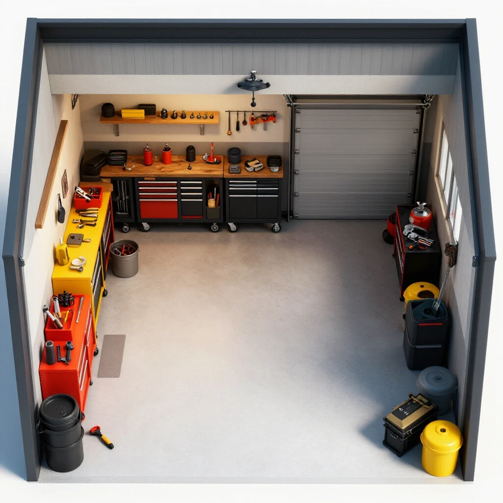
In my early days, I kept my raw steel rack at the back of the shop because it was out of the way. However, every time I needed to cut a frame, I had to carry 20-foot sticks through a narrow aisle, past the welding station, to the cold saw at the front. I was essentially running a marathon every week just moving material. A professional advanced workshop layout should prioritize a “linear” or “U-shaped” flow.
I recommend using a simple “Spaghetti Diagram.” Take a printout of your shop floor plan and draw a line for every trip you make during a standard project. If the lines cross over each other repeatedly, you have a bottleneck. I found that moving my saw closer to the roll-up door reduced my material handling time by 30%.
Defining Machine Zoning and Access Boundaries
Machine zoning is the practice of grouping tools based on their function and the mess they create. It ensures that “dirty” processes like grinding do not interfere with “clean” processes like CAD/CAM work or final assembly. Proper zoning also includes maintaining clear access paths for maintenance and safety.
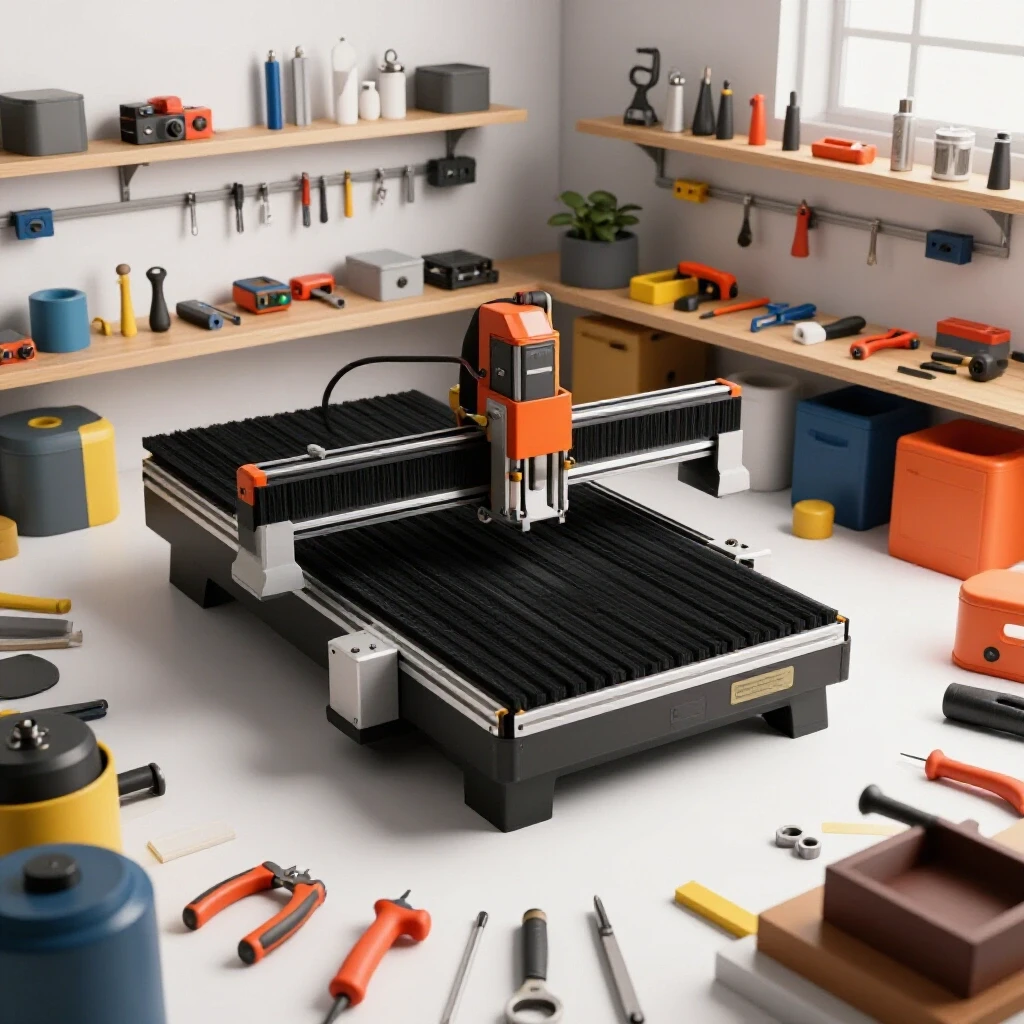
I follow a strict 3-foot minimum access zone rule. Every piece of machinery, especially a CNC plasma table setup, needs at least 36 inches of clear space around its perimeter. This isn’t just for safety; it is for workflow. If you have to shuffle boxes to change a slat on your water table, you are wasting time.
| Layout Feature | Linear Flow Pattern | U-Shaped Flow Pattern |
|---|---|---|
| Material Entry | One end of the shop | Same side as exit |
| Tool Placement | Sequential along a wall | Around the perimeter |
| Best For | Narrow, long shops | Square or wide shops |
| Travel Distance | Minimal for long parts | Minimal for small parts |
| Footprint | High | Compact |
Quantifying Manual Labor Intervals for Better Throughput
Measuring production cycles requires documenting the exact duration of each fabrication step using simple manual tools. By logging prep, cutting, and assembly times, you can pinpoint exactly where a project stalls and which tasks require more efficient tooling or better staging. This data removes the guesswork from your daily schedule.
To do this effectively, I use a basic notebook and a stopwatch. I break every project down into four categories: Setup, Processing, Handling, and Cleanup. Interestingly, most fabricators find that “Processing” (the actual cutting or welding) only accounts for about 25% of the total time. The rest is “waste” that can be optimized.
- Setup: Time spent finding files, changing consumables, or adjusting jigs.
- Processing: The time the machine is running or the arc is on.
- Handling: Moving parts from the saw to the welding table.
- Cleanup: Clearing chips or slag before the next step.
Building on this, I started logging these times for every repetitive part I made. I discovered that my “setup” time for the CNC plasma table was nearly twenty minutes because my computer was across the room. By moving the controller closer and standardizing my tooling files, I cut that down to five minutes.
Identifying Bottlenecks Through Direct Observation
A bottleneck is any point in your process where the flow of work is restricted, causing a pile-up of parts. In a small shop, this is often a single-purpose machine or a specific manual task like hand-grinding. Identifying these delays requires watching the work happen in real-time without making excuses for the slow parts.
When I integrated my first CNC system, I thought it would solve all my problems. Instead, it created a bottleneck at the deburring station. The machine cut parts faster than I could clean them. By measuring the “deburr time” per part, I realized I needed to invest in a vibratory tumbler or better abrasive tools to keep up with the automation.
Optimizing Electrical Infrastructure for High-Output Machinery
Upgrading to professional-grade machinery often requires 3-phase power, which provides more consistent torque and efficiency for motors. Understanding how to use rotary phase converters or static converters allows home-based shops to run industrial equipment on standard single-phase residential service. This transition is a major milestone in scaling a fabrication shop.
Most residential shops have 240V single-phase power. However, industrial-grade welders and CNC mills often run on 3-phase power. I faced this when I bought an old industrial air compressor. I had to choose between a Rotary Phase Converter (RPC) and a Variable Frequency Drive (VFD).
A rotary phase converter uses a dedicated motor to generate a third “leg” of power. It is robust and can power multiple machines at once. A VFD is better for single motors where you need speed control. For a scaling shop, a rotary converter is usually the backbone that allows you to buy cheaper, used industrial equipment that hobbyists can’t run.
Balancing Phase Loads and Electrical Safety
Phase balancing is the process of ensuring that the voltage across all three legs of a 3-phase system is as equal as possible. Unbalanced loads can cause motors to overheat, lose torque, and eventually fail. This is critical when running sensitive electronics alongside heavy inductive loads like motors.
I recommend using a multimeter to check your voltages while the machine is under load. You want your legs to be within 5% of each other. In my shop, I had to adjust the capacitors on my converter to get the “manufactured leg” to stay stable when my CNC gantry started moving. If the voltage drops too low, your stepper or servo motors might lose steps, ruining a costly piece of material.
| Converter Type | Pros | Cons | Ideal Use Case |
|---|---|---|---|
| Static Converter | Inexpensive, quiet | Only 2/3 rated power | Small, light-duty motors |
| Rotary (RPC) | Runs multiple tools | Loud, uses idle power | Main shop power source |
| Digital/VFD | Clean power, speed control | One unit per motor | CNC spindles, lathes |
Designing High-Volume Air Management and Dust Collection
Effective air management involves calculating the Cubic Feet per Minute (CFM) required to remove particulates and fumes at the source. It requires balancing duct size, static pressure loss, and filtration stages to ensure a safe, clean environment during high-output operations. Poor air quality is a silent production killer that leads to fatigue and equipment wear.
When you scale up, a single-stage shop vac isn’t enough. You need a multi-stage cyclone system. The “cyclone” separates the heavy chips before they hit the filter, which maintains your CFM levels for longer periods. In my shop, I designed my ductwork using 6-inch main lines that taper down to 4-inch drops. This keeps the air velocity high enough (around 4,000 feet per minute) to prevent dust from settling inside the pipes.
Calculating Static Pressure and Duct Efficiency
Static pressure is the resistance the air faces as it moves through your ducts, filters, and bends. High static pressure reduces the actual CFM reaching your tool, meaning your “2,000 CFM” collector might only be pulling 800 CFM at the machine. Calculating this involves looking at the length of your pipe runs and the number of 90-degree elbows.
I learned the hard way that “flex hose” is the enemy of efficiency. Every foot of ribbed flex hose has about three times the resistance of smooth metal ducting. As a result, I replaced almost all my flex lines with rigid spiral pipe. This simple change increased the suction at my sanding station by nearly 40%, keeping the fine dust out of the rest of the shop.
- Target Velocity: 3,500–4,000 FPM for wood chips; 4,500–5,000 FPM for metal dust.
- Filter Rating: Aim for HEPA or 1-micron filters to capture the most dangerous fine particles.
- Maintenance: Check static pressure gauges weekly to know when to pulse or clean your filters.
Integrating CNC Systems into the Production Workflow
Transitioning to automated cutting involves more than just buying a machine; it requires a systematic approach to gantry leveling, torch height control, and file preparation. Successful integration focuses on reducing the “setup-to-cut” time through standardized CAD/CAM procedures and material handling. Automation should simplify your life, not add more layers of frustration.
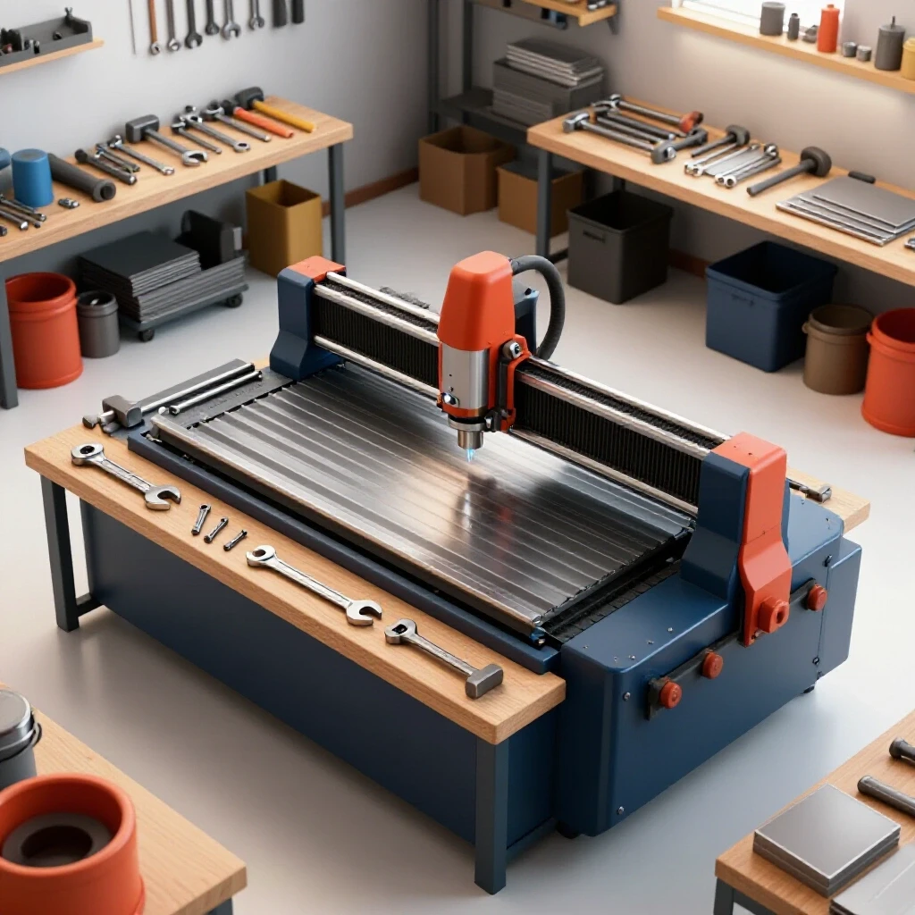
When I set up my CNC plasma table, I spent the first month chasing “ghosts” in the cuts. The gantry wasn’t perfectly level, and the torch was diving into the metal. I had to go back to basics. I used a precision machinist’s level and a dial indicator to ensure the rails were parallel within 0.005 inches over the full 4-foot span.
Efficiency in CNC workflows also depends on your software stack. I found that creating a library of “standardized lead-ins” and “cut charts” for different thicknesses of steel saved me hours of trial and error. Instead of guessing the feed rate for 3/16-inch plate every time, I just select my “3/16 Steel” preset and hit start.
Managing CAD/CAM and Tooling Files
CAD (Computer-Aided Design) and CAM (Computer-Aided Manufacturing) are the bridge between your idea and the physical part. Organizing these files is just as important as organizing your physical tool chest. If you spend thirty minutes looking for the right version of a drawing, your automation isn’t saving you any time.
I use a simple numbered filing system for my projects. Every file is named with the date, the material type, and the version number. This prevents the “Final_Final_v2” naming trap. Additionally, I keep a physical “Cut Log” next to the machine where I record the air pressure, amperage, and tip size used for every successful run. This manual tracking is the foundation of a professional workflow.
- Level the Frame: Use heavy-duty leveling feet and anchor them to the concrete.
- Square the Gantry: Use the 3-4-5 triangle method to ensure the X and Y axes are perfectly perpendicular.
- Calibrate Steps: Run the machine a set distance (like 12 inches) and measure the actual travel with a scale.
- Test Torch Height: Ensure the initial sensing and the arc voltage control are responding correctly.
Creating a Visual Workflow Matrix for Your Shop
A workflow matrix is a physical or digital chart that tracks the status of every project as it moves through the different “zones” of your shop. It provides an immediate visual representation of where work is stalled and helps you prioritize tasks based on machine availability. For a micro-manufacturer, this is the simplest way to manage multiple projects at once.
I keep a large whiteboard on my shop wall. It is divided into columns: Design, Prep, CNC, Welding, Finishing, and Shipping. Every project gets a magnetic tag. If I see five tags in the “Welding” column and none in “CNC,” I know I need to stop cutting and start melting metal. This prevents me from over-producing parts that just sit on the floor and take up space.
Tracking Performance Metrics and Maintenance
Maintenance is often the first thing to be ignored when a shop gets busy, but it is the most common cause of unexpected delays. I use a “Machine Safety and Maintenance Checklist” for every major tool. For the CNC plasma, this includes checking the air dryer for moisture and cleaning the rack and pinion gears every Monday morning.
I also track my “Scrap Rate.” If I am ruining more than 5% of my material due to machine errors or layout mistakes, I stop and recalibrate. High-volume fabrication requires high-volume consistency. By tracking these metrics manually in a simple spreadsheet, I can see trends over months that I would miss day-to-day.
- Machine Spacing: Ensure 3-foot clearance for all moving gantries and material loading.
- Air Quality: Monitor the color of your desiccant beads in the air line daily.
- Power Balance: Check your rotary converter voltage under load once a month.
- Tooling Life: Track how many pierces you get per plasma electrode to predict change-outs.
Low-Barrier Next Steps for Workshop Evolution
The transition from a hobby shop to a professional fabrication space doesn’t happen overnight. It is a series of small, calculated improvements. If you are feeling overwhelmed, start by simply carrying a notebook for one week. Write down every time you have to stop what you are doing to go find a tool or move a piece of scrap.
Once you have that data, pick the biggest time-waster and fix it. Maybe it is moving your welder closer to the assembly table, or finally installing that 3-phase converter so you can use a more powerful grinder. These small changes build the “lean” foundation you need to successfully integrate automation and scale your throughput.
Remember, the goal isn’t to work harder; it is to make the shop work for you. By mapping your process times and identifying where the minutes are leaking away, you can reclaim your time and focus on the high-level fabrication work you actually enjoy.
FAQ: Frequently Asked Questions
What is the most common cause of delays in a fabrication shop?
In my experience, the most frequent delay is “material handling.” This includes the time spent moving raw stock, searching for specific pieces, or clearing a path to a machine. By reorganizing your layout to follow a linear flow, you can often cut your production time by 20% without buying a single new tool.
How do I know if I need a rotary phase converter?
If you want to use industrial-grade machinery (like a heavy-duty mill, lathe, or large air compressor) that requires 3-phase power, and you only have standard residential service, a rotary phase converter is your best option. It is more reliable than a static converter and allows you to run multiple machines simultaneously.
Why is static pressure important in dust collection?
Static pressure is the resistance in your ductwork. If your pipes have too many bends or are too small, the air can’t move fast enough to carry dust away. This leads to clogged pipes and poor air quality. Keeping your duct runs straight and using smooth, rigid pipes helps maintain high airflow (CFM).
How often should I level my CNC plasma table?
You should check the level of your machine during the initial setup and again after any major move or heavy impact. In a home-based shop, concrete floors can settle over time. I check mine every six months with a precision level to ensure the gantry isn’t binding, which can cause motor wear and jagged cuts.
What is a “Spaghetti Diagram” and how do I make one?
It is a simple map of your shop where you draw lines representing your movement during a task. To make one, print your floor plan, grab a pen, and trace your steps as you build a project. The areas where the lines are thickest are your “high-traffic” zones and are usually where your biggest bottlenecks are located.
Can I run a CNC machine on a phase converter?
Yes, but you must be careful. CNC electronics are sensitive to voltage fluctuations. You need a “CNC-rated” rotary phase converter or a high-quality digital phase converter that provides balanced voltage across all three legs to prevent damage to the machine’s controllers and drives.
What is the 3-foot rule in shop layout?
This is a safety and efficiency guideline that suggests keeping at least 36 inches of clear space around every machine. This allows enough room for the operator to move freely, provides access for maintenance, and ensures that you aren’t tripping over cords or scrap while the machine is running.
How do I calculate the CFM I need for my shop?
Start by looking at the requirements for your largest tool (usually a planer or sander). Most small shop tools need between 400 and 800 CFM at the machine. To account for losses in the ductwork, you typically need a collector rated for 1,000 to 2,000 CFM to ensure you have enough suction at the end of the line.
What is the difference between stepper and servo motors on a CNC?
Stepper motors move in fixed “steps” and are generally more affordable but can lose their position if they hit an obstacle. Servo motors use a “closed-loop” system with encoders to constantly check their position. Servos are faster and more accurate for high-output fabrication but come with a higher capital cost and a steeper learning curve.
How do I track “setup time” effectively?
Start your stopwatch the moment you stop one task to begin preparing for the next. This includes finding the drawing, loading the material, and setting the tool offsets. If your setup time is longer than your actual cut time, look for ways to standardize your files or organize your tooling to reduce that gap.
(This article was written by one of our staff writers, Edward Sinclair. Visit our Meet the Team page to learn more about the author and their expertise.)