How to Perform First Article Inspections in Shop (Tutorial)
I remember standing over a heavy equipment trailer frame ten years ago, feeling a knot in my stomach. I had spent three days cutting and tacking the steel, but as I stood back, something looked off. When I finally pulled out my tape measure and square to check the first major sub-assembly, I realized the main rails were out of parallel by nearly half an inch. I had ignored the critical step of verifying my first few joints and measurements before moving forward. That mistake cost me two days of grinding and several hundred dollars in wasted material. Since then, I have treated the verification of the very first part of any project as the most important moment in the shop.
In my 14 years as a fabricator and engineer, I have learned that structural failures rarely happen because of a single massive error. They happen because of small, uncorrected mistakes that stack up. Whether you are building a workbench, a vehicle rack, or a structural frame in your garage, checking your work early is the only way to ensure the final product is safe. This process is about more than just checking a length; it is about validating your entire setup, from your gas flow to your weld penetration.
Foundations of Initial Part Verification
Initial part verification is the process of comparing your first physical piece against your design drawings. This ensures that your material choice, cutting accuracy, and layout are correct before you commit more time and resources to the rest of the project. It acts as a final gatekeeper against design errors.
When I start a project, I begin by looking at the material stress thresholds. For most shop projects, we use A36 structural steel. This material has a yield strength of about 36,000 PSI. If my first part shows signs of deformation or if my design places a load too close to that limit, I know I need to stop. I check the material for any mill scale issues or surface rust that might interfere with weld quality.
Understanding the load path is also vital. A load path is the route a force takes through a structure to the ground. If my first joint is misaligned, that path is broken. I use this initial check to confirm that my joints are tight and that the fit-up allows for full weld penetration. A gap that is too wide can lead to a weak joint, while a gap that is too tight can cause the metal to warp as it heats up.
Essential Tools for Manual Dimensional Checks
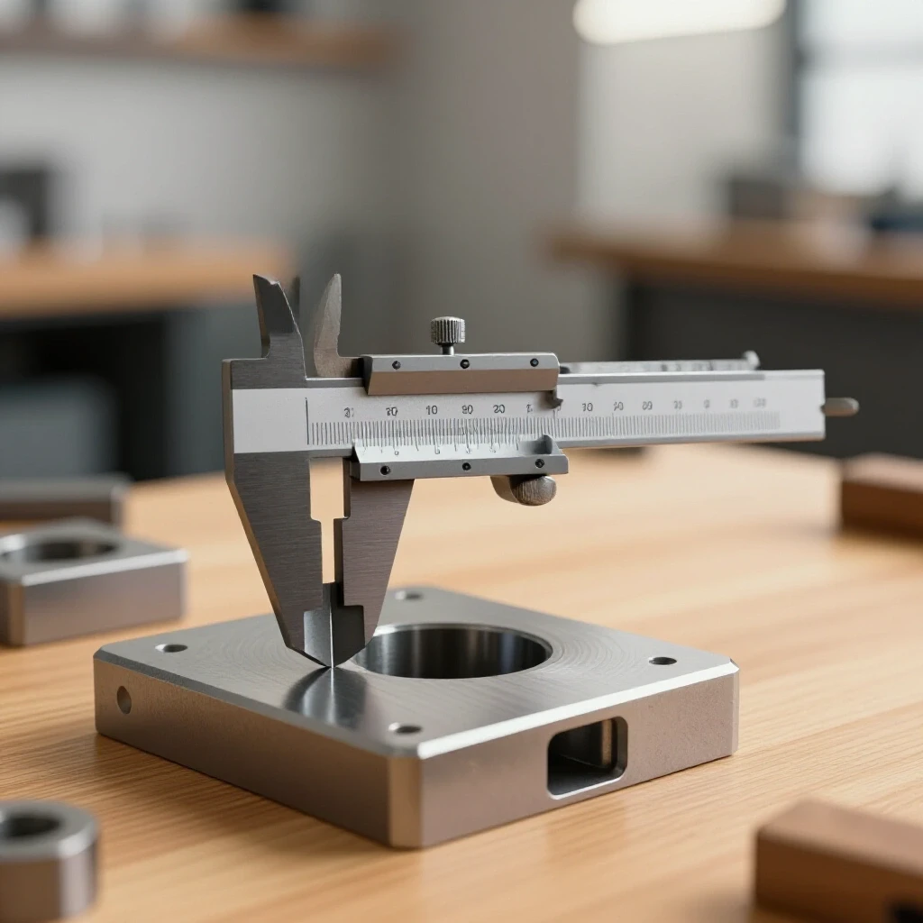
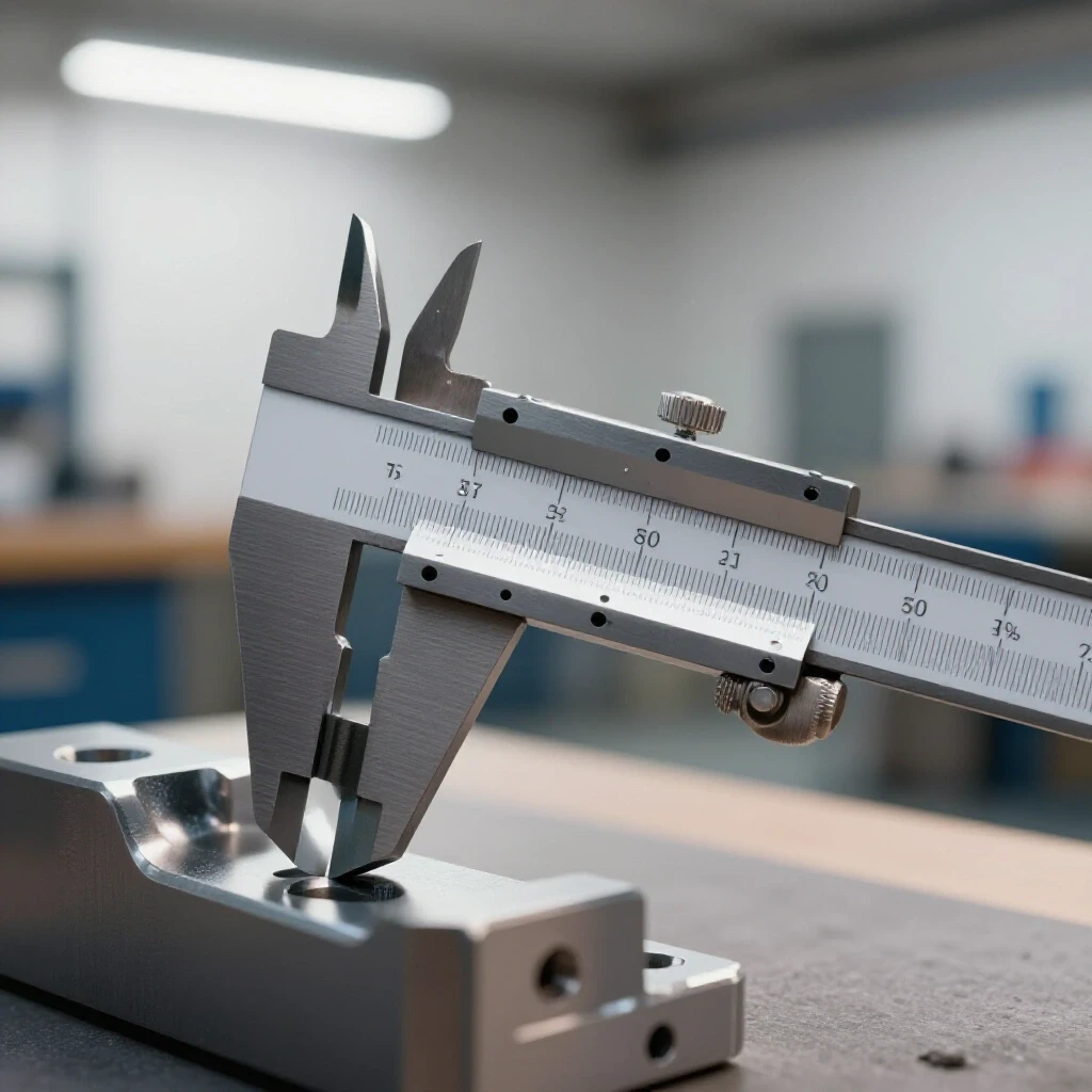
Using manual instruments like digital calipers, micrometers, and height gauges allows you to confirm that your workpiece meets the required tolerances. These tools are the front line in preventing “tolerance stack-up,” where small errors grow into major assembly failures. Reliable measurements are the backbone of shop safety.
You do not need expensive automated systems to verify your work. I rely on a specific set of manual tools that have never let me down. These tools help me catch errors that the naked eye would miss.
- Digital Calipers: I use these for checking material thickness and small hole diameters. I look for accuracy within 0.001 inches.
- Micrometers: When I need to check the diameter of a pin or a shaft, a micrometer gives me precision down to 0.0001 inches.
- Height Gauges: These are excellent for marking out hole locations on a vertical surface to ensure they match the print.
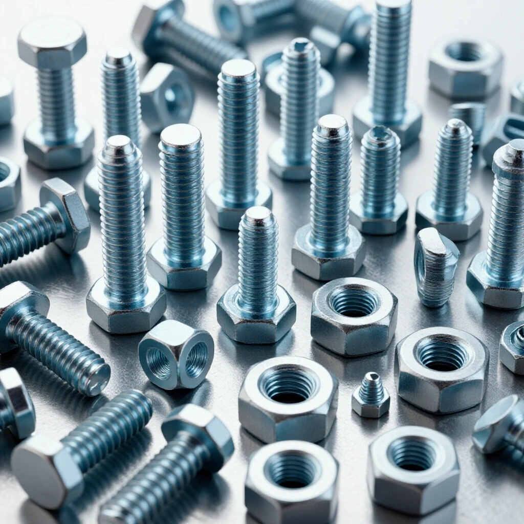
- Thread Plugs and Ring Gauges: These verify that any tapped holes or threaded rods are the correct size and pitch.
- Combination Squares: A high-quality square is essential for checking that your first corner is exactly 90 degrees.
By checking the first part with these tools, I can adjust my saws or jigs before I cut the rest of my material. If my first cut is 1/16th of an inch too short, every subsequent part will be wrong unless I catch it now.
Why Weld Porosity Destroys Structural Integrity
Weld porosity refers to tiny gas bubbles trapped in the cooling metal, which create voids that weaken the joint. Identifying these defects during the initial check prevents structural failure under load, ensuring the assembly can handle its intended weight. Porosity is often a sign of a deeper system failure.
In my shop, I treat porosity as a major red flag. It usually means my welding gas flow rate is wrong or there is a draft in the room. I aim for a gas flow of 15 to 20 CFH (cubic feet per hour) for MIG welding indoors. If I see “Swiss cheese” holes in my first weld, I stop immediately.
Porosity acts like a perforated line on a piece of paper. Under stress, the metal will tear along those tiny holes. This is a common cause of structural metal load capacity failure. To prevent this, I include a “gas check” on my workshop safety checklist. I also ensure my base metal is cleaned with a flap disc to remove oil or paint, which are leading causes of gas bubbles in the weld pool.
| Weld Defect | Common Cause | Visual Indicator | Solution |
|---|---|---|---|
| Porosity | Low gas flow or wind | Small holes on surface | Increase flow to 15-20 CFH |
| Undercut | Excessive heat or speed | Groove at the weld toe | Lower voltage or slow down |
| Lack of Fusion | Low heat or bad angle | Weld “sitting” on top | Increase heat; check angle |
| Slag Inclusion | Poor cleaning (Stick/Flux) | Dark spots inside weld | Clean between passes |
Analyzing the Heat-Affected Zone (HAZ)
The heat-affected zone is the area of base metal that didn’t melt but had its properties changed by welding heat. Checking this area during your first piece verification helps you understand if you are over-softening the metal or causing brittle fracture risks. The HAZ is often the weakest point of a completed project.
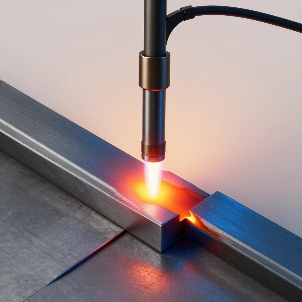
Every time you weld, you are heat-treating the metal next to the joint. If you use too much heat, you can make the metal brittle or too soft. I look for excessive discoloration around my first weld. While some blue or straw color is normal, a wide band of dark purple or grey can indicate that I have stayed in one spot too long.
This area is where brittle fractures usually start. A brittle fracture is a sudden break that happens without much bending. It is dangerous because it gives no warning. By inspecting the HAZ of my first part, I can adjust my travel speed or wire feed settings to keep the heat input within a safe range. This is especially important for garage fabrication safety, where we often work with thinner materials that are easy to overheat.
Establishing a Reliable Shop Safety Layout
A safe workshop layout minimizes hazards like fire, tripping, and flash burns. Integrating safety into your first-piece check means verifying that your ventilation, gas lines, and PPE are functioning correctly before you proceed with a full day of fabrication. A messy shop leads to messy, unsafe work.
When I am verifying my first part, I also verify my environment. I check that my welding curtains are positioned to protect others from “arc flash.” I ensure my welding helmet is set to the correct shade. For most of my work, I use Shade 10 to 13 filters depending on the amperage.
I also look at my ventilation. Welding fumes are toxic, and a small shop can fill up with smoke quickly. I use a smoke extractor or a high-volume fan to pull air away from my face. If I notice smoke lingering around my first weld, I know my ventilation needs adjustment. This is a key part of my workshop safety checklist that I perform before the real work begins.
Practical Steps for Manual Part Inspection
Verifying the first part is a systematic process. I follow a specific order to ensure I don’t miss anything. This routine has saved me from dozens of structural failures over the years.
- Visual Inspection: I look for obvious defects like cracks, heavy spatter, or visible warping.
- Dimensional Check: I use my calipers and squares to verify the part matches the drawing.
- Joint Alignment: I check that the pieces are centered and that there is no “hi-lo” (one piece sitting higher than the other).
- Weld Profile: I use a fillet gauge to ensure the weld is the correct size. A weld that is too small won’t hold the load, and one that is too large causes unnecessary distortion.
- Cleanliness Check: I ensure all slag and spatter are removed so I can see the true condition of the metal.
If the first part passes these five steps, I feel confident moving on to the rest of the build. If it fails even one, I stop and find the root cause. It is much easier to fix a mistake on one bracket than on twenty.
Structural Load Testing and Safety Margins
Load testing involves applying weight to a prototype or first part to see how it reacts under stress. Using safety margins, like a 4:1 factor, ensures that your project can handle unexpected forces without collapsing or permanently deforming. Never design a project to work at its absolute limit.
In engineering, we use a safety factor to account for unknowns. If I expect a shelf to hold 100 pounds, I design it to hold 400 pounds (a 4:1 safety factor). When I verify my first part, I sometimes perform a “destructive” or “non-destructive” load test.
For a non-destructive test, I might apply the intended working load and measure if the part deflects (bends) and then returns to its original shape. If it stays bent, the metal has reached its “yield point,” and the design is unsafe. For critical joints, I might even use a simple dye penetrant kit. You spray a red dye on the weld, wipe it off, and then apply a white developer. If there is a tiny crack, the red dye will bleed through the white powder, showing me a failure I couldn’t see with my eyes.
Managing Metal Distortion and Warping
Metal expands when it gets hot and shrinks as it cools. This movement can pull your project out of alignment, even if your initial measurements were perfect. Controlling this distortion is a major part of validating your first assembly.
I have learned that the sequence of welding matters as much as the weld itself. On my first part, I experiment with “back-stepping” or “stitching” my welds. Instead of one long bead, I do several short ones in different areas. This spreads the heat more evenly.
If my first part warps more than 1/8th of an inch over a four-foot span, I know I need better fixturing. I might need to clamp the part to a thick steel table or use temporary “strongbacks” to hold it straight. Verifying the straightness of the first part tells me if my clamping strategy is working.
Troubleshooting Common Fabrication Errors
When a part doesn’t meet the requirements, you have to be a detective. I look at three things: the machine, the material, and the operator (me). Often, the issue is something simple that was overlooked during setup.
- Machine Issues: Is the wire tension correct? Is the polarity set right for the gas I am using?
- Material Issues: Is the steel actually the thickness it was labeled? (Sometimes 11-gauge is sold as 10-gauge).
- Operator Issues: Was my travel angle too steep? Did I move too fast?
By analyzing the first failure, I turn a mistake into data. This data allows me to adjust my technique for the rest of the project. This is how you move from being a hobbyist to a skilled fabricator.
Final Verification Checklist for the Shop
Before I call the first part “good” and start the production run, I run through this final checklist. It ensures that both the part and the shop are ready for the work ahead.
- Are all dimensions within the allowed tolerance (e.g., +/- 1/16″)?
- Is the weld profile consistent with no visible porosity or undercut?
- Is the shielding gas tank showing enough pressure for the whole job?
- Are all safety guards on grinders and saws in place?
- Is the fire extinguisher charged and within reach?
- Does the part fit into the next stage of the assembly without forcing it?
Taking ten minutes to go through these questions prevents hours of rework later. It also builds a habit of excellence that keeps you and your projects safe.
Frequently Asked Questions
What is the most common mistake during a first-piece check? The most common mistake is rushing. Fabricators often want to see the finished product and skip measuring the first part thoroughly. This leads to “accumulated error,” where small mistakes in each part make the final assembly impossible to put together.
How do I know if my weld penetration is deep enough on the first part? For a first-piece check, you can perform a “cut and etch” test if you have scrap material. Weld two pieces together using your settings, cut through the weld with a saw, and polish the cross-section. Applying a mild acid (like naval jelly) will reveal the “nugget” of the weld, showing you exactly how deep the heat penetrated the base metal.
Why is my metal warping even when I use clamps? Clamps can only do so much against the physical force of shrinking metal. If your first part is warping, try reducing your heat input or using a “tack and check” method. Place small tacks every few inches and re-measure everything before laying down the final beads.
What should I do if my first part is slightly out of square? If it is only a tiny bit off, you might be able to correct it with “heat shrinking” or by clamping it in the opposite direction before welding the other side. However, if it is significantly off, it is safer to cut the tacks, grind the joints clean, and start over. Never try to “weld over” a bad fit-up.
What gas flow rate is best for a home garage? In a typical garage with the door cracked for ventilation, 15 to 20 CFH of a 75/25 Argon/CO2 mix is standard for MIG welding. If you have a strong breeze, you may need to increase it to 25 CFH or use a wind shield, as the wind will blow away your shielding gas and cause porosity.
How do I check for cracks if I don’t have fancy equipment? A simple visual check under a bright light with a magnifying glass can catch many surface cracks. You can also use the “ring test” for larger cast parts—hit the part lightly with a hammer. A solid part will ring clearly, while a cracked part will often produce a dull thud.
Why does the heat-affected zone (HAZ) matter so much for safety? The HAZ is where the metal’s internal structure has changed. If you get it too hot, the steel can become as soft as butter or as brittle as glass. In a structural project, the metal will almost always fail in the HAZ before it fails in the weld itself.
What is the best way to measure a long frame for squareness? Use the “3-4-5” rule or measure the diagonals. If you measure from the top-left corner to the bottom-right, and then from the top-right to the bottom-left, the two numbers should be identical. If they are different, your frame is a trapezoid, not a rectangle.
Can I use a standard tape measure for first-piece verification? For large frames, a tape measure is fine, but be aware of the “hook” at the end. Make sure it moves freely to account for internal and external measurements. For anything requiring precision under 1/32nd of an inch, you should move to calipers or a steel rule.
What should I do if my material thickness varies from the plan? If your material is thinner than the design calls for, you must recalculate your load capacity. Using 1/8″ steel when the plan calls for 3/16″ reduces the strength of the structure significantly. It is usually better to wait and get the correct material than to risk a structural failure.
(This article was written by one of our staff writers, James Harlan. Visit our Meet the Team page to learn more about the author and their expertise.)