How to Reduce Tool Chatter on Metal Lathes (DIY Tutorial)
There is a specific sound that every experienced machinist dreads. It is a high-pitched, ear-piercing scream that signals a failure in the cutting process. When you hear that resonance, you know that your surface finish is being ruined, your carbide inserts are chipping, and your lathe is under unnecessary stress. I have spent 15 years in shops where a deadline is breathing down my neck, only to have a simple turning operation turn into a fight against physics.
Early in my career, I spent three days trying to turn a long, slender shaft for a hydraulic assembly. No matter what I did, the middle of the part looked like a threaded rod rather than a smooth cylinder. I tried changing speeds. I tried different tools. I even tried holding a piece of rubber against the part while it spun. Nothing worked until I stopped guessing and started measuring. That was the moment I realized that vibration in metalworking is not a ghost; it is a mechanical variable that can be isolated and controlled.
Systematic troubleshooting is the only way to move past the frustration of poor surface finishes and destroyed tools. Instead of turning knobs at random, we need to look at the lathe as a series of connected parts. If one part is loose or out of alignment, the whole system vibrates. My goal is to help you break down these vibrations into manageable pieces so you can get back to clean, precise cuts.
The Physics of Harmonic Instability in Metal Turning
Vibration during a cut is essentially a self-excited harmonic loop where the tool and the workpiece bounce off each other at a high frequency. This occurs when the cutting forces exceed the structural stiffness of the machine setup. Understanding this relationship allows you to identify whether the issue is the machine, the tool, or the material.
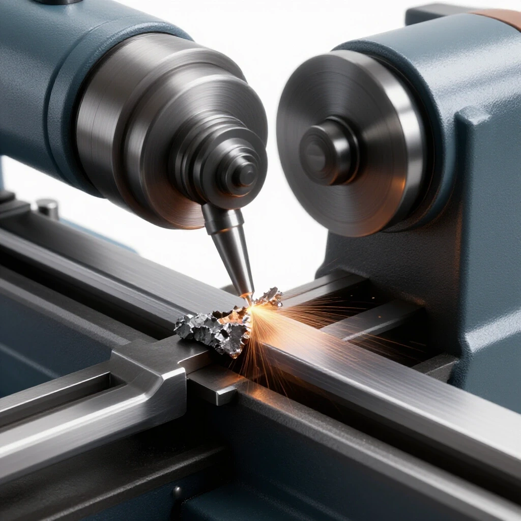
When a cutting tool enters a piece of metal, the material resists. This resistance creates pressure. If the tool or the workpiece deflects even a tiny amount, that pressure changes. As the pressure drops, the tool snaps back into position, only to hit the material again. This cycle repeats hundreds or thousands of times per second. This is what we call chatter. It leaves behind a pattern of waves on the metal surface. These waves then “teach” the tool to vibrate even more on the next pass.
To stop this, we must break the cycle. We do this by increasing rigidity or by changing the frequency of the vibration. In my experience, most shop owners try to fix this by simply slowing down the spindle. While that can help, it often masks a deeper mechanical issue like a loose gib or a worn bearing.
Mechanical Baselines: Eliminating Excess Movement in the Lathe
Before you change your cutting settings, you must ensure the machine itself is a solid foundation. Mechanical troubleshooting starts with the parts of the lathe that are supposed to stay still but might be moving under load. If your carriage or cross-slide has internal play, no amount of speed adjustment will result in a clean cut.
The first place I look is the gib adjustment. Gibs are the tapered or flat strips of metal that take up the play in the dovetail ways of your cross-slide and compound rest. Over time, these wear down. I recommend a “shake test” with a dial indicator. Mount the indicator on the bed and push against the cross-slide. If you see more than 0.001 inches of movement, your gibs are too loose.
Next, check the spindle bearings. If the spindle has any radial or axial play, the entire workpiece will wobble. For a standard hobbyist or small professional lathe, you want to see less than 0.0005 inches of runout on the internal taper of the spindle. If you find more, you may need to adjust the bearing preload.
Comparison of Mechanical Rigidity Factors
| Component | Common Symptom of Failure | Diagnostic Target |
|---|---|---|
| Spindle Bearings | Consistent vibration at all speeds | < 0.0005″ Runout |
| Cross-Slide Gibs | Vibration increases with depth of cut | < 0.001″ Play |
| Compound Rest | Tool “dives” into the work | Lock bolts must be torqued |
| Tailstock | Tapered finish or chatter on long parts | Alignment within 0.001″ |
Tooling Geometry and Setup Optimization
The way you hold your cutting tool is often the primary source of instability. In my 15 years of diagnosing shop errors, I have found that tool overhang is the single most common mistake. A tool that sticks out too far acts like a diving board, bouncing every time it hits a hard spot in the metal.
The rule of thumb I follow is the 3:1 ratio. The length of the tool sticking out of the holder should never be more than three times its thickness. If you are using a 0.500-inch shank tool, try to keep the overhang under 1.5 inches. If you must go longer, you have to reduce your cutting pressure significantly to compensate for the loss of stiffness.
Tool height is another critical factor. If the tool is below center, it tends to “rub” and then “dig,” which causes a rhythmic bounce. If it is too far above center, the flank of the tool rubs against the workpiece, creating heat and friction-induced vibration. I use a dedicated height gauge or a thin piece of shim stock held against the workpiece to ensure the cutting edge is exactly on the centerline or perhaps 0.001 to 0.002 inches above it.
Tooling Variables and Their Impact
- Rake Angle: A positive rake angle reduces cutting pressure, which can help stop vibration in softer materials.
- Nose Radius: A large nose radius creates more contact area between the tool and the metal. While this improves finish, it also increases the chance of resonance. If you have chatter, try a tool with a smaller nose radius (e.g., 0.015 inches instead of 0.032 inches).
- Lead Angle: A tool that enters the cut at a 90-degree angle pushes the force back into the spindle. A tool with a 45-degree lead angle pushes some of that force sideways, which can sometimes stabilize a flimsy setup.
Workpiece Dynamics: Managing Long and Slender Parts
The material you are cutting has its own resonant frequency. Long, thin parts are notoriously difficult to machine because they lack the mass to resist the tool’s pressure. When the length-to-diameter ratio exceeds 3:1, you can no longer rely on the chuck alone to hold the part steady.
For long parts, a tailstock with a live center is mandatory. However, even a tailstock can introduce issues if it is not aligned. If the tailstock is even 0.003 inches off-center, it will put a “bow” in the workpiece. This tension creates a spring-like effect that feeds into tool vibration. I always use a test bar to verify that my tailstock is perfectly concentric with the spindle before starting a long run.
If the part is longer than six times its diameter, you must use a steady rest or a follow rest. A steady rest stays fixed to the lathe bed and supports the part at a specific point. A follow rest moves with the carriage, supporting the part directly opposite the cutting tool. These tools act as mechanical “dampers” that soak up the energy before it can turn into a harmonic scream.
Speed and Feed Interplay: Breaking the Harmonic Cycle
Once the machine is tight and the tool is set correctly, you must look at your operational variables. Surface Feet Per Minute (SFM) and Inches Per Revolution (IPR) are the two levers you can pull to change the frequency of the cut. If the system is vibrating, you need to move the frequency away from the “sweet spot” of the resonance.
Common wisdom says to slow down when you hear chatter. This is often true. By reducing the RPM, you lower the frequency of the impacts. However, sometimes the opposite is required. Increasing the feed rate (IPR) can actually stabilize a cut. A heavier feed rate puts more “load” on the tool, which can act like a stabilizer, pinning the tool into the material so it cannot bounce.
I often tell my students to think of it like a car on a washboard road. Sometimes slowing down makes the bumps feel worse, but speeding up lets you “float” over the top. In machining, increasing the depth of cut or the feed rate can sometimes provide the necessary pressure to stop the tool from oscillating.
Diagnostic Matrix for Speed and Feed Adjustments
- High-pitched squeal: Reduce spindle speed by 20% or increase feed rate by 10%.
- Low-frequency “rumble”: Check for loose machine components or increase spindle speed.
- Torn surface finish: Increase speed and ensure the tool is on the center line.
- Chipping inserts: Reduce the depth of cut and check for tool overhang.
DIY Damping Techniques and Shop-Made Solutions
Sometimes, even a perfectly adjusted lathe will chatter due to the specific shape of a workpiece. In these cases, we have to get creative with damping. Damping is the process of absorbing or dissipating the energy of the vibration. This is where the “art” of troubleshooting meets the science.
One of the most effective DIY tricks I have used is the “weighted wrap.” If you are turning a hollow tube that is ringing like a bell, wrap a heavy chain or a piece of lead-shot-filled hose around the outside of the part. This adds mass and changes the resonant frequency. The energy that would have gone into making noise is instead spent moving the heavy wrap.
Another method involves the tool itself. If you have a boring bar that is vibrating, you can use a “tuned mass damper.” I have seen machinists drill a hole in the end of a custom boring bar and fill it with sand or lead shot. This internal “loose” mass moves out of phase with the vibration, effectively cancelling it out.
Checklist for Effective Damping
- Lead Weights: Secure lead tape or weights to the non-cutting side of the workpiece.
- Rubber Pads: Place a thick rubber pad between the tool post and the compound rest (only for light finishing cuts).
- Sand Filling: For hollow parts, fill the interior with dry sand and plug the ends to absorb internal harmonics.
- Belt Tension: Ensure your lathe drive belts are not “flapping.” A loose belt can introduce a secondary vibration that looks like tool chatter.
Case Study: The Case of the Resonant Boring Bar
I once had a job involving a deep internal bore in a piece of 4140 alloy steel. The hole was 8 inches deep, but only 1.5 inches in diameter. I was using a long carbide-shank boring bar, which should have been stiff enough. However, as soon as I reached the 4-inch mark, the lathe started screaming. The finish looked like a topographic map.
I started my systematic diagnostic process. First, I checked the spindle runout—it was 0.0002 inches, which was perfect. Next, I checked the gibs on the cross-slide and found they were slightly loose. I tightened them until I felt a slight drag. The noise improved but didn’t go away.
Finally, I looked at the tool height. I realized that as the bar reached deeper into the hole, the cutting pressure was causing the bar to flex downward. This moved the cutting edge below center, which worsened the chatter. I adjusted the tool holder so the bar started 0.005 inches above center. When the cutting pressure hit, the bar flexed down to exactly the centerline. The chatter vanished instantly. This experience taught me that troubleshooting is often about predicting how the machine will move under load, not just how it looks while sitting still.
Step-by-Step Lathe Calibration Checklist
To maintain a chatter-free environment, I follow this monthly calibration routine. Keeping a log of these measurements helps you spot trends before they become failures.
- Clean the Ways: Remove all chips and old oil from the dovetails.
- Check Gib Play: Use a dial indicator to measure movement in the cross-slide and compound. Adjust to 0.001″ or less.
- Inspect Belts: Look for cracks or flat spots that could cause rhythmic vibrations.
- Verify Center Height: Use a dead center in the tailstock to check that your tool post is holding tools at the correct elevation.
- Spindle Preload: Spin the spindle by hand (with the motor off). It should feel smooth but not “free-wheeling.” If it spins for a long time after a push, the preload might be too loose.
- Tailstock Alignment: Turn a 6-inch piece of scrap between centers without a steady rest. Measure both ends with a micrometer. If the diameters differ, your tailstock is out of alignment.
Conclusion: Mastering the Machine
Solving vibration issues on a manual lathe is a test of patience and logic. It is rarely a single “magic” fix. Instead, it is the result of tightening three or four different areas by a small amount. When you eliminate the play in the gibs, optimize your tool overhang, and find the right balance of speed and feed, the machine rewards you with a silent, effortless cut and a mirror-like finish.
The next time you hear that high-pitched ring, do not get frustrated. See it as a signal from the machine telling you that something is out of balance. Stop the lathe, grab your dial indicator, and start working through the variables. With a systematic approach, you can turn any manual lathe into a precision instrument.
Frequently Asked Questions
Why does my lathe chatter more on certain materials like aluminum?
Aluminum is softer than steel, but it is also more prone to “built-up edge” (BUE). When bits of aluminum weld themselves to the tool tip, the geometry changes, leading to rubbing and vibration. Using a sharper tool with a higher rake angle and proper lubrication usually solves this.
Can a dull tool cause vibration?
Yes. A dull tool does not “cut” the metal; it “pushes” it. This increased pressure causes the tool and the workpiece to deflect more, which triggers the harmonic cycle of chatter.
How do I know if my spindle bearings are the problem?
If you get chatter even on short, thick workpieces with very little tool overhang, the spindle bearings are likely the culprit. Check for heat around the spindle nose after a long run; excessive heat usually indicates a bearing issue.
Does the type of tool post matter?
Absolutely. A traditional “lantern-style” tool post is much less rigid than a modern “quick-change” wedge-style tool post. If you are struggling with rigidity, upgrading to a solid wedge-style holder is one of the best investments you can make.
What is the ideal feed rate to avoid chatter?
There is no single “ideal” rate, but a common mistake is feeding too slowly. A feed rate that is too light (less than 0.002 IPR) can cause the tool to rub rather than cut. Try increasing your feed to at least 0.005 IPR to see if the vibration stabilizes.
Can I use a dampening material inside the lathe bed?
Some old-school machinists fill the hollow legs or the base of their lathe with dry sand or concrete to increase the mass of the machine. This helps absorb floor vibrations and can make the entire setup more stable.
Why does the vibration change as the tool moves closer to the chuck?
The workpiece is most rigid near the chuck. As the tool moves away, the “lever arm” of the workpiece increases, making it easier to deflect. If chatter starts mid-way through a cut, it is a clear sign that you need more workpiece support, like a steady rest.
What is “backlash” and does it cause chatter?
Backlash is the play in the lead screws. While backlash itself doesn’t always cause chatter, it can allow the carriage or cross-slide to “climb” the cut if the forces are not controlled. Always “take up” the backlash by turning the handle in the direction of the cut before starting.
How does the depth of cut affect harmonics?
A deeper cut increases the load. Sometimes, a very shallow “finishing” cut is more prone to chatter because there isn’t enough pressure to keep the tool seated. Increasing the depth of cut can often “pin” the system and stop the noise.
Should I lock the carriage during a facing cut?
Yes. Whenever you are moving one axis (like the cross-slide for facing), you should lock the other axes (like the carriage). This eliminates one more source of potential movement and vibration.
(This article was written by one of our staff writers, Paul Whitaker. Visit our Meet the Team page to learn more about the author and their expertise.)