How to Repair and Reinforce Sagging Steel Farm Gates (Guide)
I have spent over a decade in prototype shops and my own garage, and I can tell you that few things are as frustrating as a heavy steel gate that drags through the dirt every time you try to open it. It is a classic engineering failure of leverage and gravity. Most factory-made farm gates are built light to save on shipping costs, which means they eventually succumb to structural deflection. When that frame starts to sag, it is not just an eyesore; it puts massive stress on your hinge posts and makes the latching mechanism useless.
In my experience building utility trailers and custom chassis, I have learned that steel is a living material. It moves when you heat it, and it bends when you load it. Restoring a drooping gate requires more than just a quick bead of weld. You have to understand the forces at play, plan your cuts to account for the kerf (the width of the material removed by the blade), and sequence your welds so the heat actually helps pull the frame back into a square position. This guide breaks down my personal process for turning a tired, warped barrier into a rigid, functional piece of equipment that will stay true for years.
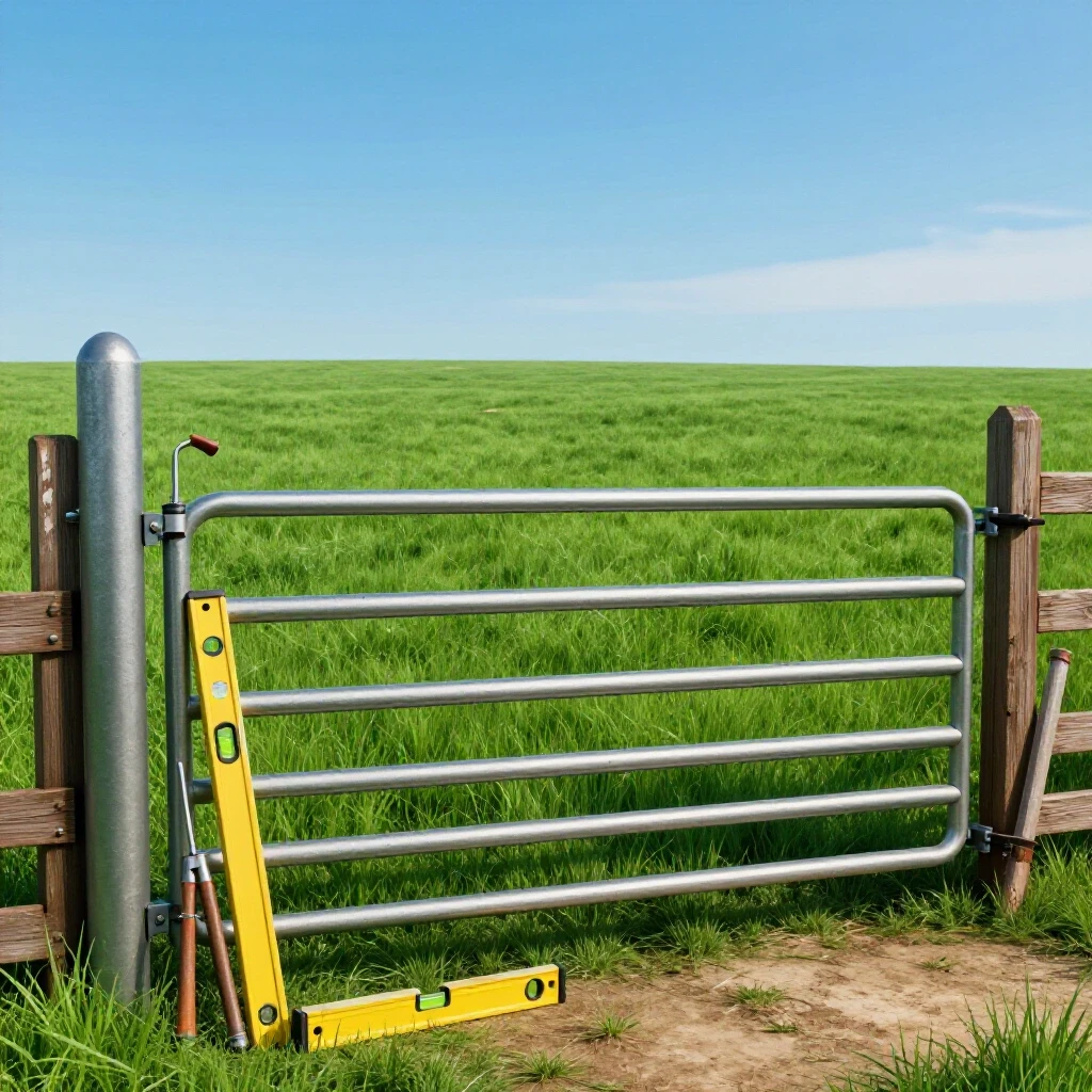
Measuring Deflection and Assessing Structural Fatigue
Deflection is the vertical distance a gate drops from its intended horizontal plane, usually measured at the latch end. Assessing fatigue involves checking the hinge post, hinge pins, and the frame’s corner joints for cracks or bends that compromise the gate’s ability to stay square under its own weight.
Before I even reach for my welder, I spend time with a string line and a level. I start by checking the hinge post. If the post is leaning, no amount of steel reinforcement on the gate itself will fix the sag. I use a four-foot level to check for plumb on two sides of the post. If the post is solid, I move to the gate frame. I stretch a string from the top hinge corner to the bottom latch corner. This diagonal line reveals exactly how much the frame has “racked” or turned into a parallelogram.
Most gates fail because the vertical members are too thin to resist the twisting force of the horizontal rails. I look for “necking” or stretching in the steel near the top hinge. If I see cracked paint or flaking rust, that is a sign the metal has exceeded its elastic limit—the point where it can no longer spring back to its original shape. I document these measurements in my build log to ensure my reinforcements are sized correctly for the load.
- Measure the gap at the latch: A 1/2-inch sag at the hinge can result in a 3-inch drop at the end of a 12-foot gate.
- Check hinge pin alignment: Ensure pins are perfectly vertical within +/- 1/16th inch.
- Inspect factory welds: Look for “cold” welds that may have detached from the tubing.
Selecting Materials for Rigid Reinforcement
Choosing the right steel profile is the difference between a long-term fix and a temporary patch. Angle iron provides high rigidity against bending, while flat bar is lighter but better suited for tension-only applications like diagonal strapping across the frame.
When I plan a reinforcement, I look at the weight-to-strength ratio. Adding too much heavy steel can actually make the sag worse by increasing the dead load on the hinges. For most 1.5-inch to 2-inch tube gates, I prefer using 1″ x 1″ x 1/8″ angle iron for compression braces. If I am looking for a lighter tension-based solution, a 1″ x 3/16″ flat bar works well.
The goal is to create a triangle within the rectangular frame. Triangles are structurally stable because they cannot change shape without changing the length of one of their sides. I avoid using thin-wall conduit or “rebar” because rebar is difficult to weld cleanly and lacks the predictable yield strength of structural A36 steel.
Material Comparison for Gate Bracing
| Material Type | Weight per Foot | Best Use Case | Rigidity Rating |
|---|---|---|---|
| 1″ x 1/8″ Angle Iron | 0.80 lbs | Compression (Diagonal) | High |
| 1″ x 3/16″ Flat Bar | 0.64 lbs | Tension (Diagonal) | Medium |
| 1/2″ Steel Rod | 0.67 lbs | Tension (Adjustable) | Low |
| 1″ Square Tubing (14ga) | 1.03 lbs | Perimeter Repair | Very High |
Calculating Kerf and Planning Accurate Square Cuts
Kerf is the width of the slot left by a cutting tool, such as a chop saw blade or an angle grinder disc. Planning accurate cuts requires subtracting this value from your measurements to ensure that the final pieces fit tightly against the existing frame without large gaps.
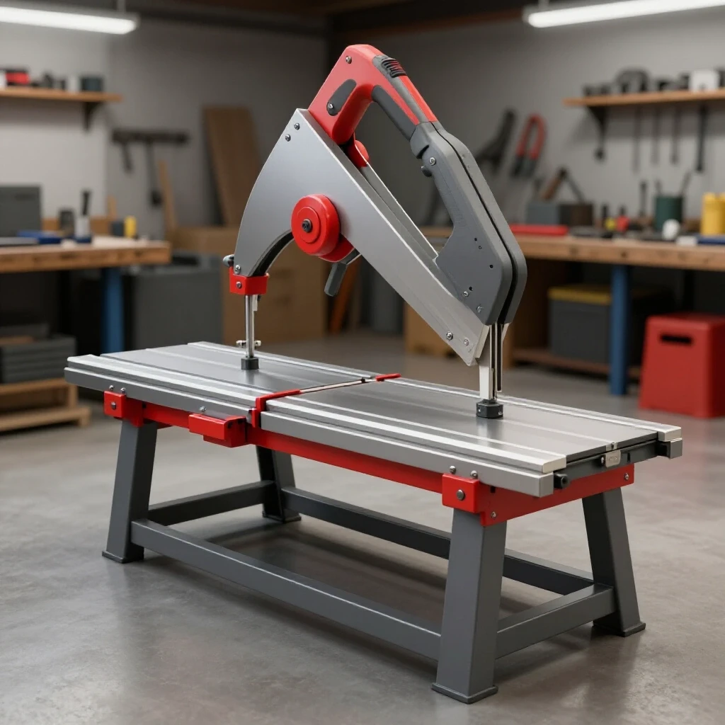
In my shop, I use a standard 14-inch abrasive chop saw which typically has a 3/32-inch or 1/8-inch kerf. If I measure a diagonal brace to be exactly 48 inches and I cut right on the line, my piece will end up 47 and 7/8 inches long. That 1/8-inch gap is a “weld killer.” It forces you to fill the space with extra heat, which leads to more warping.
I always mark my steel with a fine-point soapstone or a scribe. I “leave the line,” meaning I cut on the waste side of my mark. For the diagonal cuts needed to fit a brace into a corner, I use a protractor to find the angle. Most farm gates are not perfectly square to begin with, so I often use a piece of cardboard to make a template of the corner angle before I touch the steel.
- Measure the internal diagonal of the gate section.
- Subtract 1/16-inch for a “snug fit” tolerance.
- Mark the angle based on the rise and run of the frame.
- Account for the 1/8-inch blade thickness.
Setting Up Workshop Jigs and Layout Fixtures
A jig is a temporary structure or tool used to hold parts in the correct position during the fabrication process. Layout fixtures ensure that the gate remains flat and square while you apply heat, preventing the “potato chip” effect where the frame twists along its length.
You don’t need a professional welding table to get good results. When I’m working on a large gate, I often use my concrete garage floor or a pair of heavy-duty sawhorses. The key is to create “stops.” I’ll bolt or clamp scrap blocks of wood or steel to my work surface to trap the gate in a square position.
I use the “3-4-5 rule” to verify squareness: measure 3 feet on one side, 4 feet on the adjacent side, and the diagonal should be exactly 5 feet. Once the gate is squared and clamped down, I can fit my reinforcement braces. If the gate is already sagging, I use a floor jack or a come-along to pull the frame slightly past square (about 1/4-inch over-correction) before clamping. This accounts for the metal’s tendency to “relax” once the clamps are removed.
- Use at least four heavy C-clamps or F-clamps.
- Space supports every 3 to 4 feet to prevent bowing.
- Ensure the work surface is level within 1/8-inch across the span.
The Science of Weld Sequencing and Distortion Control
Weld sequencing is the specific order in which you lay down your welds to manage the internal stresses caused by heating and cooling. Distortion control uses the natural shrinkage of cooling metal to pull a structure into the desired shape rather than away from it.
Every time you lay a bead, the cooling metal shrinks by about 3% to 5% in volume. This creates a powerful “pull” on the joint. If I weld the entire top side of a brace first, it will pull the gate into a bow. To combat this, I use the “back-stepping” technique and staggered tacks.
I start with small tacks, no larger than 1/4-inch, at each corner. I check for square again. Then, I move in a “cross-pattern,” similar to tightening lug nuts on a car wheel. I weld two inches on the top left, then move to the bottom right. This keeps the heat input balanced across the entire frame. For thin-walled farm gates, I keep my MIG welder set to a lower voltage and a faster wire speed to avoid burning through the tubing.
Weld Sequence and Heat Management
| Step | Action | Purpose |
|---|---|---|
| 1 | Corner Tacks | Secures the geometry without high heat. |
| 2 | Opposite Side Tacks | Balances the initial “pull” of the metal. |
| 3 | Short Beads (1-2″) | Minimizes the heat-affected zone (HAZ). |
| 4 | Cooling Period | Allows the structure to stabilize before final beads. |
Installing Tension Rods and Turnbuckle Supports
Tension rods are adjustable steel cables or bars used to pull the bottom latch corner of a gate upward toward the top hinge corner. This method allows for future adjustments as the gate or the hinge post settles over time.
Sometimes, a rigid brace isn’t the best option, especially if the ground is prone to shifting. In these cases, I install a tension system. I weld a heavy-duty mounting tab at the top hinge corner and another at the bottom latch corner. I use a 1/2-inch galvanized turnbuckle and 1/4-inch steel cable or a solid threaded rod.
The beauty of a tension rod is the ability to “tune” the gate. As the gate hangs, I tighten the turnbuckle until the latch aligns perfectly. I always apply a bit of anti-seize lubricant to the turnbuckle threads. This prevents them from rusting solid, allowing for easy adjustments two or three years down the line.
- Weld tabs made from 1/4-inch flat bar.
- Ensure the diagonal runs from the top hinge to the bottom latch.
- Tighten until the gate is 1/8-inch higher than the latch post to allow for initial settling.
Correcting Heat Warp and Final Straightening Techniques
Heat warp occurs when uneven cooling causes the steel to bend or twist after welding. Final straightening involves using controlled heat or mechanical force to bring the gate back into its intended alignment.
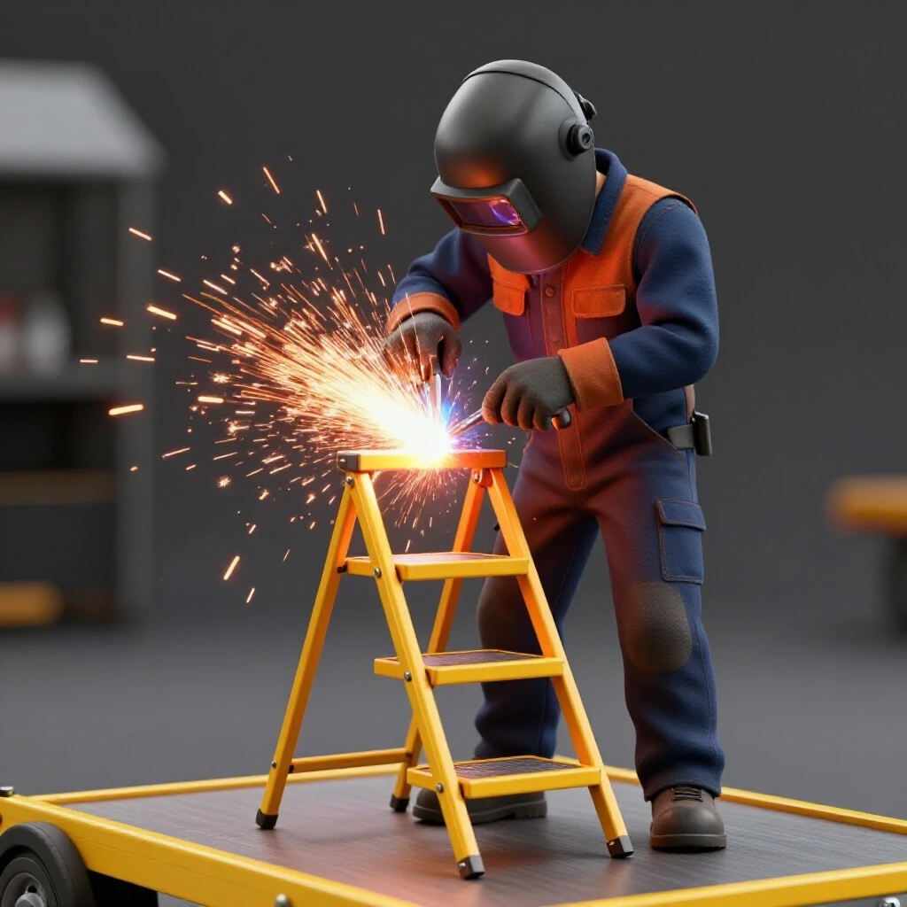
Even with the best sequencing, you might find a slight twist in the frame. This is where I use “flame shrinking” or mechanical leverage. If a rail is bowed upward, I can heat a small triangular “V” on the top of the rail with an oxy-acetylene torch. As that spot cools, it shrinks more than the surrounding metal, pulling the rail back down.
However, for most DIY builders, mechanical force is safer. I’ll often put the gate back in my “stops” and use a long lever (like a 6-foot pry bar) to gently nudge the frame back into plane. I check my progress frequently with a straightedge. A gate that is flat within 1/16-inch over an 8-foot span is a professional-grade result.
- Check for “twist” by looking down the edge of the gate (sighting).
- Use a heavy hammer and a wood block to “settle” welds (stress relieving).
- Avoid over-correcting; steel has a “memory” and may move slightly over 24 hours.
Essential Tools for Gate Restoration Projects
A successful repair depends on having the right tools for both the layout and the fabrication phases. Using the correct equipment reduces errors in cutting and ensures that your welds penetrate deeply enough for a structural bond.
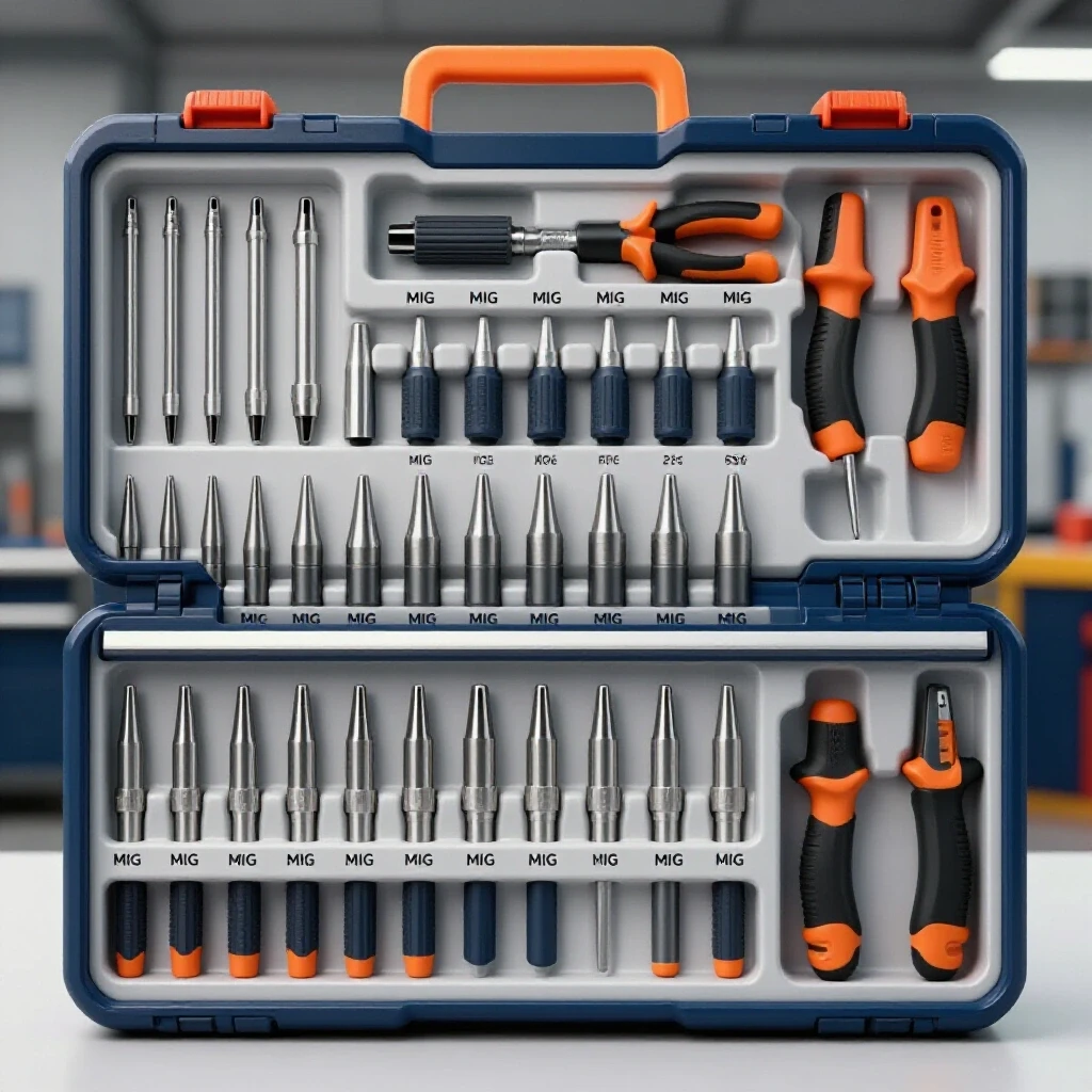
I keep a specific kit for these projects. Beyond the welder, the most important tool is a high-quality angle grinder with a variety of discs. I use “flap discs” (60 or 80 grit) for cleaning the steel before welding and “thin-cut” wheels for precise trimming. A digital angle finder is also a lifesaver when you’re trying to fit a brace into a frame that isn’t perfectly 90 degrees.
- MIG Welder: 140-amp minimum for 1/8-inch steel.
- Angle Grinder: For cleaning rust and beveling edges.
- Magnetic Squares: To hold braces in place for initial tacking.
- C-Clamps: At least four 6-inch clamps for layout.
- String Line: For checking long-distance deflection.
- Wire Brush: To clean the weld area (essential for galvanized gates).
Safety Considerations When Welding Galvanized Steel
Many farm gates are galvanized (zinc-coated) to prevent rust. Welding on galvanized steel releases zinc oxide fumes, which can cause “metal fume fever,” a flu-like illness that is extremely unpleasant.
Whenever I work on a galvanized gate, I use an angle grinder to strip the coating back at least one inch from the weld zone. I do this until I see bright, shiny steel. I always work in a well-ventilated area, preferably outdoors or with a high-volume fan at my back to push the fumes away. I also wear a P100-rated respirator under my welding helmet. It is a small step that makes a huge difference in long-term health.
- Grind off all zinc coating before striking an arc.
- Wear a respirator with organic vapor/particulate cartridges.
- Use a dedicated “galvanized” welding wire if available (E71T-GS for flux-core).
Final Assembly and Hinge Maintenance
The final step is re-hanging the gate and ensuring the hinges can handle the newly reinforced weight. A rigid gate is only as good as the pivot points it rotates on.
After I finish the welding and cleaning, I inspect the hinge pins one last time. I often find that the original pins are bent. I replace them with heavy-duty 3/4-inch or 1-inch pins if possible. I also apply a thick layer of marine-grade grease to the pins. This reduces friction and prevents the “squeak” that often precedes a hinge failure.
When I hang the gate, I start with the top hinge. I let the gate hang naturally, then align the bottom hinge. If the gate still has a slight sag, I can often compensate by adjusting the hinge nuts. I aim for a latch gap of 1/4-inch to 1/2-inch. This provides enough clearance for the gate to swing freely even if the ground heaves slightly in the winter.
Conclusion
Restoring a sagging steel gate is a masterclass in practical fabrication. It forces you to deal with the realities of leverage, the physics of heat distortion, and the importance of an accurate layout. By following a structured process—measuring the deflection, selecting the right reinforcement materials, and using a disciplined weld sequence—you can turn a failing piece of farm equipment into a rigid structure that lasts for decades.
The biggest takeaway from my years in the shop is that preparation is 90% of the job. If you spend the time to square your frame and clamp it properly before you ever pull the trigger on your welder, the metal will work with you rather than against you. Take it slow, manage your heat, and always keep your string line handy.
FAQ: Frequently Asked Questions About Steel Gate Repair
What is the best way to stop a gate from sagging permanently?
The most effective permanent fix is a diagonal compression brace made of angle iron, running from the bottom hinge corner to the top latch corner. This creates a rigid triangle that prevents the frame from racking.
Can I weld a galvanized gate without stripping the coating?
No. Welding through galvanization causes porous, weak welds (porosity) and releases toxic zinc fumes. Always grind the coating down to bare steel before welding.
Why did my gate warp even more after I welded the brace?
This usually happens due to improper weld sequencing. If you weld one side completely without alternating, the cooling metal pulls the frame in that direction. Use small tacks and staggered beads to balance the heat.
How much over-correction should I put in a sagging gate?
I typically pull the sagging corner about 1/4-inch higher than square before clamping and welding. This accounts for the natural “spring back” and weld shrinkage that occurs when the clamps are released.
What size welder do I need for farm gate repairs?
A standard 120V MIG welder (140 amps) is usually sufficient for the 1/8-inch or 14-gauge steel found in most farm gates. If you are using flux-core wire, ensure it is rated for outdoor use and galvanized surfaces.
Is flat bar or angle iron better for bracing?
Angle iron is superior for compression (pushing) because it resists bending. Flat bar is excellent for tension (pulling) and is easier to fit in tight spaces.
How do I calculate the angle for my diagonal brace?
You can use a digital angle finder or the “rise over run” method. Measure the height and width of the inner frame, then use a protractor to mark the cut line on your bracing material.
Should I use a turnbuckle or a solid brace?
Use a solid brace (angle iron) for a “set it and forget it” fix on a stable post. Use a turnbuckle and tension rod if your hinge post is prone to shifting or if you want the ability to adjust the gate height later.
What is “kerf” and why does it matter for my cuts?
Kerf is the thickness of the material removed by your saw blade. If you don’t account for it, your braces will be slightly too short, leading to large gaps that are difficult to weld and prone to warping.
How do I check if my gate is square without a giant square?
Use the 3-4-5 rule. Measure 3 feet along the horizontal rail and 4 feet up the vertical rail. The diagonal distance between those two marks should be exactly 5 feet if the corner is 90 degrees.
(This article was written by one of our staff writers, Robert Kline. Visit our Meet the Team page to learn more about the author and their expertise.)