How to Select the Right MIG Welding Wire Type (Buying Tips)
I remember standing in a quiet workshop three years ago, looking at a heavy steel engine hoist I had just finished. On the surface, the beads looked decent, but something felt off. I had used a spool of wire I found in the back of a cabinet without checking its classification or diameter. When I ran a simple load test with a hydraulic jack, I heard a sharp, metallic “crack” that echoed through the garage. That sound is the nightmare of every fabricator. It represents a failure in structural integrity, wasted material, and a potential safety hazard.
In my 14 years as a mechanical engineer and shop floor fabricator, I have learned that the bond between two pieces of metal is only as strong as the filler material you choose. Selecting the correct consumable for your Gas Metal Arc Welding (GMAW) projects is not just about making things stick together. It is about managing the heat-affected zone, ensuring the tensile strength matches your base metal, and preventing internal defects like porosity or cold lap. If you are building a trailer, a work table, or a structural frame, the wire you load into your feeder determines whether your project survives the stresses of real-world use.
Understanding Tensile Strength and Metal Stress Tolerances
Tensile strength is the maximum amount of pulling stress a material can withstand before breaking or failing. In the world of solid wire selection, this is usually indicated by the first two digits of the classification, such as “70” in ER70S-6, which represents 70,000 pounds per square inch (PSI).
When I design a structural joint, I always look at the yield strength of the base metal first. Most common A36 structural steel has a yield strength of about 36,000 PSI and a tensile strength between 58,000 and 80,000 PSI. If you use a filler metal with a lower tensile strength than your base metal, the weld becomes the weakest link in the chain. This is a recipe for a brittle fracture. I prefer to see a slight over-match or an exact match in strength to ensure the load path remains continuous across the joint.
| Wire Classification | Tensile Strength (PSI) | Common Base Metal Match | Typical Application |
|---|---|---|---|
| ER70S-3 | 70,000 | A36, A500 Grade B | Clean, new sheet metal |
| ER70S-6 | 70,000 | A36, Hot-rolled steel | General fabrication with mill scale |
| ER80S-D2 | 80,000 | 4130 Chromoly | High-strength structural frames |
| ER4043 (Aluminum) | 21,000 | 6061-T6 (General) | Non-structural aluminum hobbyist work |
| ER5356 (Aluminum) | 35,000 | 5052, 6061 (Structural) | Marine and structural aluminum |
Building on this, you must consider the safety factor. In garage fabrication safety, we often use a 2:1 or even 4:1 safety margin. If a shelf is meant to hold 500 pounds, I design it to hold 2,000 pounds. This margin accounts for minor welding defects or unexpected vibrations. Choosing a wire with a verified 70,000 PSI rating provides the baseline data needed to calculate these margins accurately.
Why Wire Diameter Dictates Structural Load Capacity
Wire diameter refers to the thickness of the solid electrode, typically ranging from 0.023 to 0.045 inches for most workshop applications. Selecting the right diameter is critical because it controls the current density and the depth of penetration into the base metal.
I once saw a fabricator try to weld 3/8-inch plate using 0.023-inch wire. He thought he could just move slower to get more metal into the joint. Instead, he ended up with “cold lap,” where the filler metal sits on top of the base metal without actually fusing to it. The thin wire didn’t carry enough current to melt the thick plate. For structural metal load capacity, you need the heat to reach the root of the joint.
- 0.023 to 0.025 inch: Best for thin gauge sheet metal (20-gauge to 1/8-inch). It keeps the heat low to prevent warping.
- 0.030 inch: The “all-purpose” choice for most hobbyists. It handles 1/8-inch to 1/4-inch material well.
- 0.035 inch: My personal favorite for structural frames. It provides excellent penetration on 1/4-inch to 1/2-inch steel.
- 0.045 inch: Primarily for heavy plate work. Requires a high-amperage machine and steady hand to manage the large puddle.
Interestingly, using a wire that is too thick for thin material is just as dangerous. It requires higher voltages that can easily blow holes through the metal or create an oversized heat-affected zone (HAZ). A large HAZ softens the surrounding metal, making it prone to bending or cracking right next to the weld bead.
Decoding Chemical Composition for Workshop Safety
The chemical composition of a welding wire includes deoxidizers like silicon and manganese that help clean the weld pool as you work. These elements are essential for preventing porosity, which are tiny gas bubbles trapped in the weld that act like “swiss cheese” and ruin structural integrity.
In my experience, ER70S-6 is the gold standard for most home shops. It contains higher levels of silicon and manganese compared to ER70S-3. These additives act as scavengers, pulling impurities and mill scale out of the molten metal and floating them to the surface as a thin layer of slag. If you are working with hot-rolled steel that hasn’t been perfectly ground to a shiny finish, the “S-6” chemistry provides a vital safety net against internal weld defects.
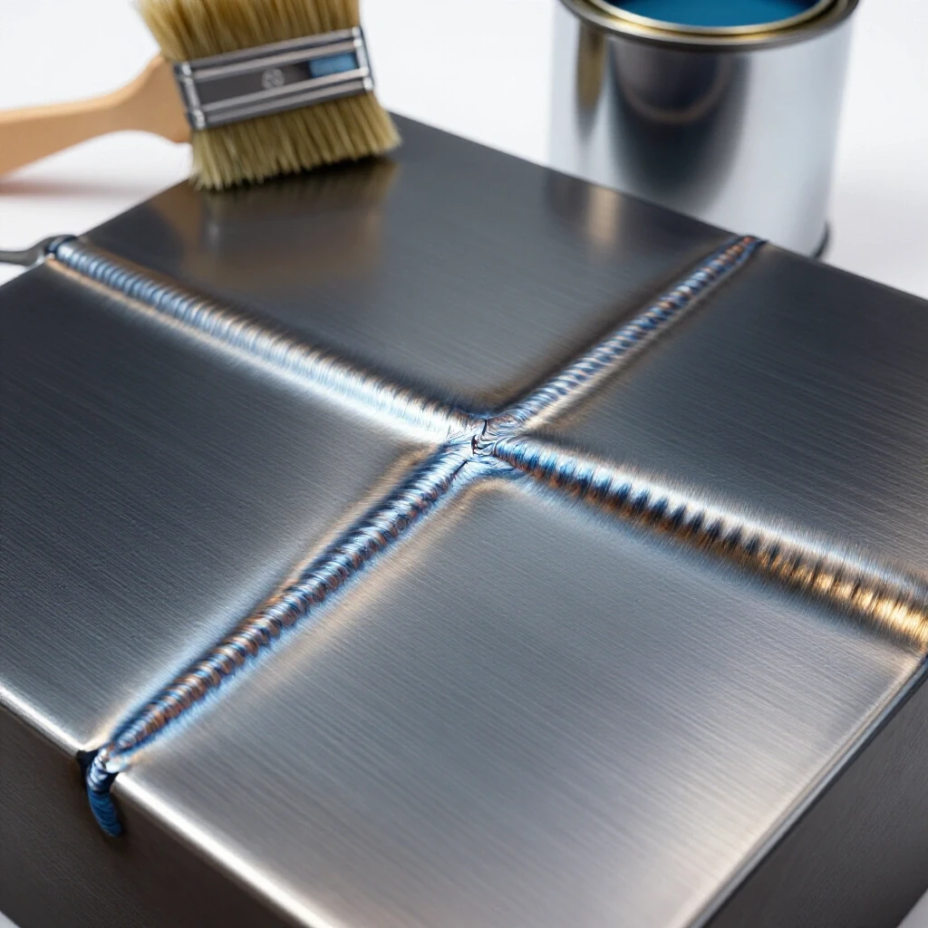
As a result of this chemistry, the weld pool stays more fluid, allowing gas to escape before the metal solidifies. When I inspect a joint, I look for a smooth, consistent ripple pattern. If I see tiny pinholes, I know the deoxidizers couldn’t keep up with the surface contamination or the gas coverage was blocked. This is why material preparation—grinding away rust and oil—is the first step in any workshop safety checklist.
Shielding Gas Compatibility and Porosity Prevention
Shielding gas protects the molten weld pool from oxygen and nitrogen in the atmosphere, which cause brittleness and holes. The type of gas you use must be compatible with your wire selection to ensure a stable arc and proper bead profile.
For most steel fabrication, I recommend a mixture of 75% Argon and 25% CO2 (often called C25). This gas provides a great balance. The Argon stabilizes the arc and reduces spatter, while the CO2 provides the deep penetration needed for structural loads. If you use 100% CO2, you will get deeper penetration and lower costs, but the spatter increases significantly. High spatter isn’t just a cosmetic issue; it can clog your gas nozzle, leading to a sudden loss of shielding and a failed weld.
- Check your gas flow rate: For most indoor shop work, 15–20 cubic feet per hour (CFH) is the sweet spot.
- Monitor air currents: Even a small fan or an open garage door can blow your shielding gas away.
- Inspect the nozzle: Keep it clean of spatter to ensure a smooth, laminar flow of gas over the wire.
If you are welding aluminum, you must switch to 100% Argon. Using a CO2 mix on aluminum will result in immediate, catastrophic failure of the joint. I have seen hobbyists make this mistake, resulting in a black, sooty mess that has zero structural strength. Always double-check your tank label before pulling the trigger.
Managing the Heat Affected Zone and Structural Weakness
The Heat Affected Zone (HAZ) is the area of base metal that was not melted but had its microstructure changed by the intense heat of the welding process. This area is often where structural failures begin because the metal can become either too soft or too brittle.
When I analyze a failure, I often find that the crack didn’t happen in the weld itself, but right next to it in the HAZ. By selecting a wire diameter that allows you to weld faster (higher travel speed), you can minimize the total heat input into the part. This keeps the HAZ small and preserves the original strength of your steel tubing or plate.
- Symptom: Discoloration far away from the weld bead.
- Cause: Excessive heat input or moving too slowly.
- Risk: Reduced load-bearing capacity and increased risk of stress cracking.
- Solution: Use the largest wire diameter your machine can handle for thick parts to increase deposition rates and decrease “dwell time.”
Diagnostic Inspection and Visual Quality Control
Visual inspection is the most powerful tool in your shop. Before you ever put a load on a structure, you must look at the weld through the lens of a critic. I use a simple checklist for every critical joint to ensure I haven’t missed a subtle error that could lead to a collapse.
- Profile Check: Is the weld face slightly convex (humped) or flat? A concave (sunken) weld is often underfilled and weak.
- Toe Fusion: Does the edge of the weld blend smoothly into the base metal, or is there a sharp notch? These notches are “stress risers” where cracks love to start.
- Undercut: Look for a groove melted into the base metal right at the edge of the weld. This effectively thins your material and reduces its structural metal load capacity.
- Porosity: Are there any visible holes? Even one or two visible pinholes usually mean there are dozens more hidden inside.
For projects that involve high stakes, like a vehicle suspension component, I use a basic “dye penetrant” kit. You spray a red dye on the weld, wipe it off, and then apply a white developer. If there is even a microscopic crack, the red dye will bleed through the white powder. It is a low-cost way to get professional-grade certainty in your garage fabrication safety protocols.
PPE Integration and Workshop Safety Layout
You cannot make good decisions about wire selection or weld quality if you are distracted by discomfort or safety fears. Proper Personal Protective Equipment (PPE) is a fundamental part of the fabrication process. When MIG welding, you are dealing with intense ultraviolet (UV) radiation and molten metal droplets.
I always wear a welding helmet with a high-quality auto-darkening filter. For MIG welding at typical hobbyist amperages (100-200 amps), a Shade 10 to 12 is necessary to protect your retinas. Furthermore, I never weld in a t-shirt. The UV rays from a MIG arc can cause “welder’s flash” burns on your skin in minutes, which feel like a severe sunburn and increase long-term health risks.
- Gloves: Use medium-weight leather MIG gloves that offer a balance between heat protection and finger dexterity.
- Respirator: Even with “clean” wire, the welding process creates fumes. A P100-rated pancake respirator fits under most helmets and protects your lungs from manganese and iron oxide particles.
- Curtains: If you share your space with others, use welding curtains to block the arc flash from bystanders.
Your workshop safety layout also matters. I keep my wire spools in a dry, climate-controlled cabinet. If wire sits out in a damp garage, it can develop a microscopic layer of rust. That rust carries hydrogen into the weld, which leads to “hydrogen embrittlement”—a condition where the weld looks perfect but can shatter like glass under a sudden load.
Structural Load Testing for the Risk-Averse Fabricator
Once the welding is done and the inspection is passed, the final step for any critical project is a controlled load test. I never assume my calculations are perfect. I want to see how the structure reacts under pressure before it goes into service.
When I built a heavy-duty shop crane, I didn’t just start lifting engines. I hung weights from it in 100-pound increments, measuring the deflection (bending) with a dial indicator. If the metal doesn’t return to its original shape after the weight is removed, you have exceeded the “elastic limit” of the material. This is a sign that your design or your joint execution is insufficient for the task.
- Static Load: Apply 125% of the intended maximum weight in a controlled environment.
- Observation: Watch the joints for any signs of “flaking” paint or mill scale, which indicates the metal is stretching.
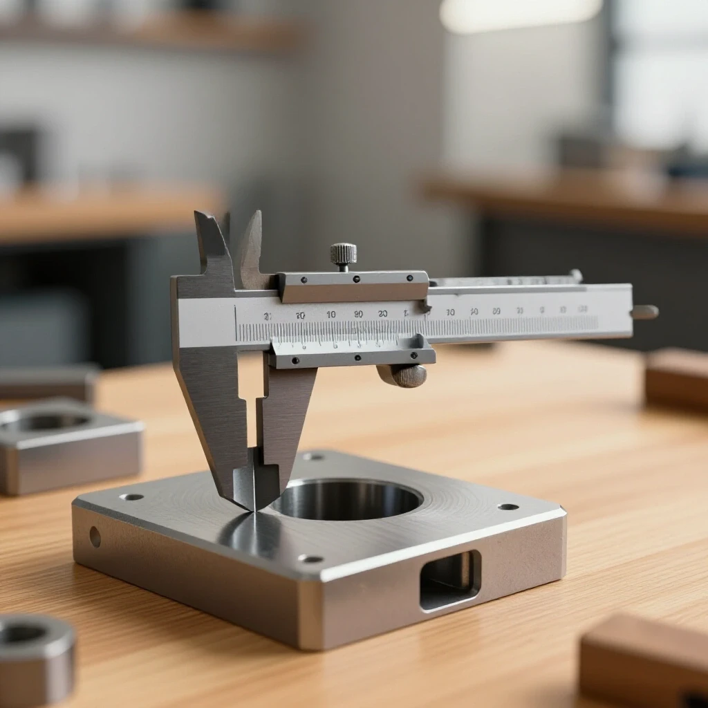
- Measurement: Use a tape measure or calipers to check if the structure has permanently deformed.
By treating every project as a data-gathering exercise, you move from “guessing” to “knowing.” This transition is what separates a hobbyist from a true fabricator.
Summary of Best Practices for Wire Selection
Choosing the right filler metal is a balance of science and practical shop floor reality. By matching your wire chemistry to your base metal, selecting the correct diameter for your material thickness, and maintaining strict safety protocols, you can build structures that last a lifetime.
- Always match or exceed the base metal tensile strength (usually 70,000 PSI).
- Use ER70S-6 for general steel to handle minor surface contaminants.
- Match wire diameter to thickness (0.030″ for light work, 0.035″ for heavy work).
- Verify gas coverage and flow rates to prevent internal porosity.
- Perform visual and physical inspections on every critical joint.
The most important tool in your shop isn’t your welder—it’s your judgment. Take the time to verify your materials, and you will never have to worry about that dreaded “crack” in the middle of a job.
Frequently Asked Questions
What happens if I use a wire that is too thin for my metal? Using a wire that is too thin, such as 0.023″ on 1/2-inch plate, results in a lack of fusion. The wire will melt, but it won’t carry enough thermal energy to melt the thick base metal. This creates a “cold” weld that may look okay on the surface but has no structural strength and can peel off under load.
Can I use ER70S-6 wire on all types of steel? ER70S-6 is highly versatile and works for most carbon steels like A36, A513, and A500. However, it is not suitable for stainless steel, cast iron, or high-alloy steels like T1 without careful consideration of the metallurgy. For standard structural tubes and plates found in most shops, it is the safest bet.
How do I know if my wire has gone “bad” from sitting in the shop? Look for any signs of dullness, dark spots, or reddish-brown rust on the surface of the wire. If the wire isn’t shiny and smooth, it can cause erratic arc performance and introduce hydrogen into the weld. This leads to porosity and brittle joints. If in doubt, clip off the outer layer of the spool or replace it.
Why is my weld bead humped up and not flat? A “humped” bead usually indicates that your heat (voltage) was too low for the amount of wire you were feeding, or your wire diameter is too large for the settings. This results in poor penetration at the toes of the weld. To fix this, you may need to increase your voltage or switch to a slightly thinner wire to get better “wet-out.”
Does the “ER” in the wire name mean something specific? Yes. “E” stands for electrode (it carries the current), and “R” stands for rod (it can be used as a filler rod in other processes). The “70” indicates a minimum tensile strength of 70,000 PSI, the “S” means it is a solid wire, and the “6” refers to the specific chemical additives used for deoxidation.
Is 100% CO2 gas safe for structural welding? Yes, 100% CO2 provides very deep penetration, which is good for thick structural steel. However, it creates a lot of spatter and a harsher arc. Most fabricators prefer a C25 mix (75% Argon/25% CO2) because it provides a cleaner weld with a better bead profile, making it easier to inspect for defects.
How often should I change my contact tip when switching wire? You must change your contact tip every time you change wire diameters. An 0.035″ wire will not fit through an 0.030″ tip, and an 0.030″ wire will wobble inside an 0.035″ tip. This wobble causes arc instability and poor electrical contact, leading to inconsistent welds.
What is the best way to prevent warping when welding long frames? Warping is caused by the contraction of the metal as it cools. To minimize this, use a wire diameter that allows for faster travel speeds (less heat soak) and use a “stitching” technique. Weld small sections in different areas of the frame rather than one long continuous bead to allow the heat to dissipate.
(This article was written by one of our staff writers, James Harlan. Visit our Meet the Team page to learn more about the author and their expertise.)