How to Set Up Quality Checkpoints in Shop Projects (Guide)
In my fourteen years on the shop floor, I have learned that metal is a deceptive medium. It feels cold, rigid, and permanent, but the moment you strike an arc or apply a load, it behaves more like a living thing. I have seen massive steel frames twist like licorice because a fabricator ignored internal stresses, and I have witnessed structural joints fail under loads they were supposedly rated for, all because of a hidden pocket of gas in a weld.
Fabrication is a series of controlled risks. Whether you are building a custom utility trailer or a heavy-duty workbench, the goal is to move from the design phase to the finished product without structural uncertainty. My approach to workshop projects is rooted in mechanical engineering and a healthy respect for physics. I don’t believe in “good enough.” I believe in verification. By building a sequence of manual inspections into your workflow, you can catch errors when they are still easy to fix, rather than discovering them when a structure fails in the field.
Establishing Structural Integrity through Material Analysis
Material analysis is the process of identifying the physical limits of your metal before the first cut. It involves checking the yield strength and tensile strength of your stock to ensure the design can handle the intended forces without permanent deformation or catastrophic snapping.
Before I start any project, I look at the yield strength of my material. Yield strength is the amount of stress a metal can take before it permanently deforms. If you bend a piece of steel and it springs back, you stayed below the yield point. If it stays bent, you crossed it. For most garage fabrication, we use A36 mild steel, which has a yield strength of about 36,000 PSI.
However, we never design a project to operate at that limit. In my shop, I apply a safety factor, usually 3:1 or 4:1. This means if I expect a joint to hold 500 pounds, I design it to hold 2,000. This margin accounts for imperfections in the metal, dynamic loads (like a bouncing trailer), and the inevitable weakening that occurs in the heat affected zone (HAZ) during welding.
Table 1: Common Material Stress Thresholds
| Material | Yield Strength (PSI) | Tensile Strength (PSI) | Common Use Case |
|---|---|---|---|
| A36 Mild Steel | 36,000 | 58,000–80,000 | General frames, brackets |
| 6061-T6 Aluminum | 40,000 | 45,000 | Lightweight structures |
| 304 Stainless Steel | 30,000 | 75,000 | Food grade, corrosion resistance |
| 4130 Chromoly | 63,000+ | 87,000+ | High-stress roll cages |
Precision Layout and the Art of the Datum
A datum is a fixed starting point or reference surface from which all other measurements are taken. Establishing a reliable datum prevents “tolerance stack-up,” where small errors in individual measurements add up to a significant misalignment in the final assembly.
In my early years, I made the mistake of measuring from the “last edge” I cut. If my first cut was off by 1/32 of an inch, and my second cut was off by another 1/32, by the time I reached the end of a frame, I was a quarter-inch out of square. Now, I use a surface plate and a height gauge for critical layouts.
A surface plate is a heavy, perfectly flat slab (often granite or cast iron) that serves as the ultimate “zero” for your shop. By placing your workpiece on the plate and using a height gauge with a carbide scribe, you can mark lines that are perfectly parallel to your base. This level of precision is vital for structural metal load capacity because it ensures that weight is distributed evenly across all joints. If one leg of a table is 1/16 of an inch shorter than the others, the load path shifts, putting unintended shear stress on the remaining connections.
Why Weld Porosity Destroys Structural Integrity
Weld porosity is a defect characterized by tiny holes or “bubbles” trapped inside the weld metal, often caused by a loss of shielding gas. These voids act as internal stress risers, significantly reducing the effective cross-section of the joint and leading to sudden brittle fractures.
When I inspect a weld, I look for “Swiss cheese” on the surface, but the real danger is often hidden underneath. Porosity is usually caused by a poor welding gas flow rate. If your flow is too low (below 15 CFH), the atmosphere contaminates the molten pool. If it is too high (above 25 CFH), it creates turbulence that pulls in air.
I keep a manual ball-type flowmeter at the torch to verify exactly what is coming out of the nozzle, regardless of what the tank regulator says. If you see porosity, stop immediately. You cannot “weld over” it. The only solution is to grind back to clean metal and start again. A porous weld might look okay from a distance, but it has no structural “backbone.”
Table 2: Diagnostic Checklist for Weld Defects
| Defect | Visual Indicator | Root Cause | Corrective Action |
|---|---|---|---|
| Porosity | Small holes or pits | Poor gas flow, wind, or dirt | Check for 15–20 CFH flow; clean metal |
| Undercut | Groove at the weld toe | Too much heat or wrong angle | Lower amperage; adjust torch angle |
| Incomplete Fusion | Weld sits “on top” of metal | Low heat or fast travel speed | Increase amperage; slow down |
| Cracking | Thin line through weld | Brittle metal or rapid cooling | Pre-heat thick sections; slow cooling |
Mastering Joint Fit-up and Root Openings
Joint fit-up refers to how tightly two pieces of metal meet before welding. Proper fit-up ensures that the weld penetrates the full thickness of the material, creating a unified structure rather than a superficial bond.
I once worked on a heavy equipment trailer where the fabricator left a 1/4-inch gap and tried to fill it with a single pass. The weld looked beautiful on the outside, but it never actually fused the “root” or the bottom of the joint. Under the first heavy load, the weld simply peeled away.
For structural joints, I aim for a root opening of about 1/16 to 1/8 of an inch, depending on the material thickness. This allows the arc to reach the very bottom of the joint. I use a set of feeler gauges or a scrap piece of TIG rod to verify this gap across the entire length of the joint. If the gap is uneven, the heat will pull the metal differently, leading to massive distortion.
Managing the Heat Affected Zone (HAZ) Weakness
The Heat Affected Zone (HAZ) is the area of base metal that was not melted but had its microstructure altered by the intense heat of welding. This region often becomes the “weak link” in a structure, as the heat can soften tempered metals or make others more brittle.
Every time you weld, you are essentially heat-treating the metal in a very localized, uncontrolled way. In my shop, I manage this by using a “staggered welding” sequence. Instead of running one long bead from left to right, I weld 2 inches on one side, move to the opposite corner for 2 inches, and let the first section cool.
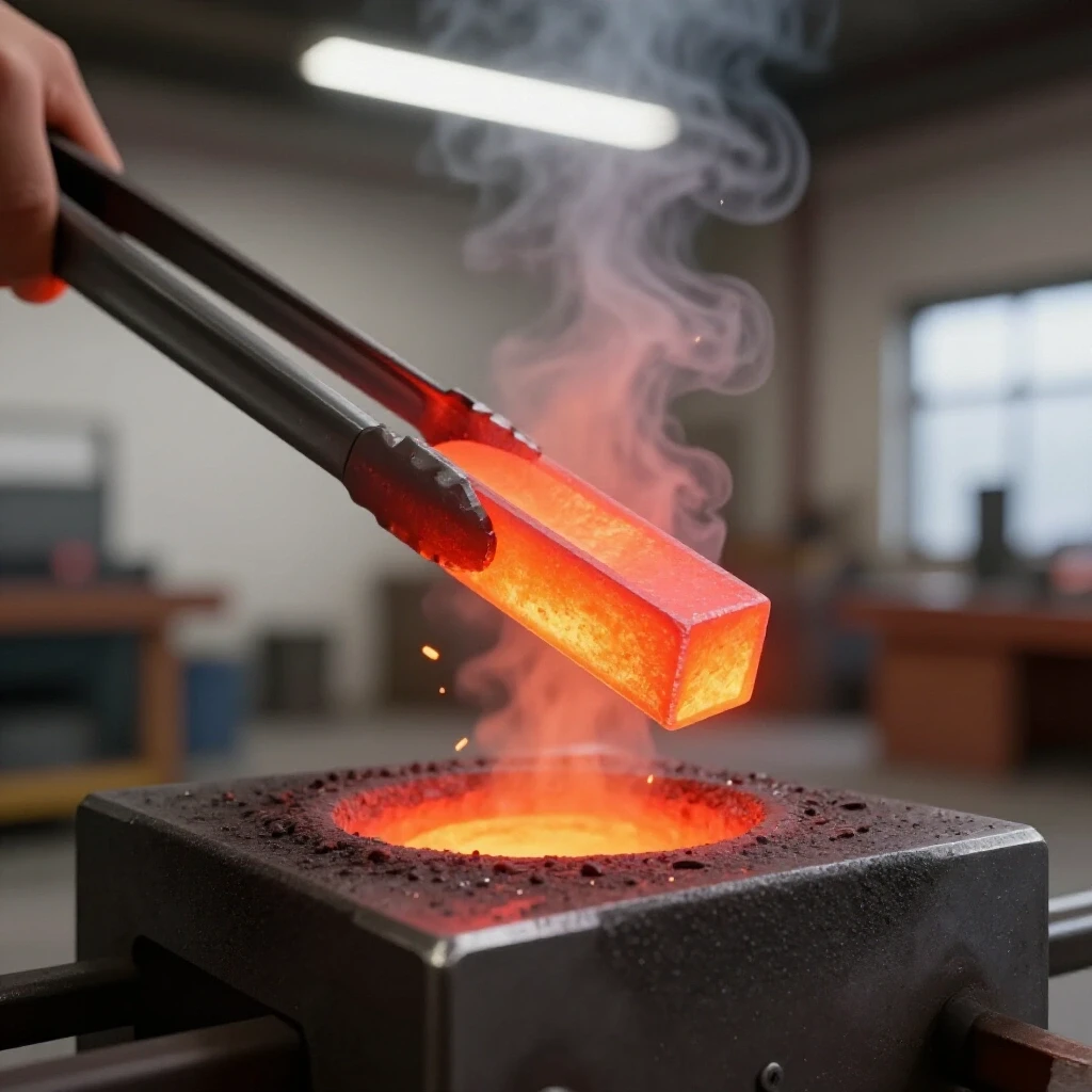
This prevents the HAZ from becoming too large. A massive HAZ leads to warping, as the metal expands and then contracts with immense force. I use a manual infrared thermometer to check the inter-pass temperature. If the metal exceeds 500°F (for mild steel), I walk away and let it air cool. Never quench a structural weld in a bucket of water; the rapid cooling can cause brittle martensite to form, which leads to immediate cracking under load.
Verification Tools for the Risk-Averse Fabricator
Diagnostic inspection is the act of using physical tools to verify that your project matches your design intent at every stage. This is the core of a garage fabrication safety strategy, as it eliminates guesswork.
I rely on a few “gold standard” manual tools that never need batteries and never lie:
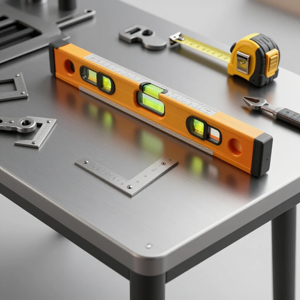
- Machinist Squares: I use a 6-inch and a 12-inch hardened steel square. I check my work after the first tack weld, after the second, and after the final pass. Metal moves.
- Dial Calipers: For measuring material thickness and hole diameters. Never trust the label on a piece of steel; always measure it.
- Fillet Weld Gauges: These allow you to measure the “leg length” and “throat” of a weld. If a design calls for a 1/4-inch fillet, a gauge will tell you if you actually achieved it.
- Scribe and Blueing Dye: For high-contrast, permanent layout lines that won’t rub off like a Sharpie mark.
Integrating PPE and Workshop Safety Protocols
Workshop safety is not just about wearing glasses; it is about creating an environment where a mistake doesn’t turn into a life-changing injury. This includes managing light radiation, fumes, and physical hazards.
I have a strict rule: the helmet stays on until the metal is cool. Many eye injuries happen when someone lifts their hood to chip slag or inspect a weld while the metal is still glowing. I recommend a Shade 10 to 13 filter depending on your amperage. For TIG welding at low amps, Shade 10 is sufficient, but if you are burning 1/8-inch 7018 rods at 125 amps, you need the protection of a Shade 12 or 13.
Ventilation is another checkpoint. I use a simple “smoke test” to verify my shop’s air currents. I light a small incense stick or a piece of cardboard; if the smoke doesn’t move toward the exhaust fan within three seconds, my ventilation is inadequate. Welding fumes contain hexavalent chromium and manganese, which are not things you want in your lungs.
Table 3: PPE Shade and Safety Ratings
| Task | Recommended Shade | Safety Standard |
|---|---|---|
| Grinding / Cutting | Clear Shield / Shade 3 | ANSI Z87.1 |
| Oxy-Fuel Cutting | Shade 5 | ANSI Z87.1 |
| MIG/TIG (50–150 Amps) | Shade 10 | ANSI Z87.1 |
| Stick/MIG (150–250 Amps) | Shade 12 | ANSI Z87.1 |
Structural Load Testing and Final Validation
Load testing is the final gate in the fabrication process. It involves applying a controlled, measured force to the finished structure to ensure it performs as calculated without signs of failure.
I never put a project into service without a “static load test.” For a workbench, this might mean stacking twice the intended weight in sandbags on the surface and leaving it for 24 hours. I use a dial indicator or a simple plumb bob to measure “deflection”—how much the metal bows under the weight.
If the structure returns to its original shape after the weight is removed, it stayed within its elastic limit. If it stays bowed, the design is flawed, and the structure is unsafe. This is the moment of truth. It is much better to have a bench collapse in your shop under sandbags than to have it fail while holding a heavy engine block or a piece of machinery.
Actionable Framework for Every Project
To keep my projects on track, I follow a rigid checklist. This prevents the “excitement of the build” from causing me to skip critical verification steps.
- Material Verification: Measure the thickness of all stock with calipers. Check for mill scale or rust that could cause weld contamination.
- Datum Establishment: Clean the surface plate. Mark all centerlines and cut lines from a single reference edge.
- Fit-up Inspection: Clamp the project in its final orientation. Use feeler gauges to verify root gaps. Ensure all corners are within 0.5 degrees of square.
- Tack and Re-check: Apply small tacks. Measure everything again. If it moved, cut the tacks and reset.
- Weld Sequence Plan: Map out the order of welds to balance heat input. Check gas flow at the nozzle.
- Post-Weld Visual: Use a magnifying glass to look for undercut or surface cracks. Measure fillet sizes with a gauge.
- Load Test: Apply a 2:1 test load in a controlled environment.
By following these steps, you transform fabrication from a “fingers-crossed” hobby into a disciplined engineering practice. You aren’t just sticking metal together; you are building something that is scientifically sound.
FAQ: Common Questions on Shop Quality and Safety
What is the most common cause of structural failure in home-built projects? In my experience, the most common cause is poor joint penetration combined with excessive heat. Fabricators often “cold lap” their welds, where the metal looks like it is attached but is actually just sitting on the surface. When a load is applied, the joint acts like a hinge and snaps.
How can I tell if my weld has good penetration without an X-ray? For a “butt joint,” you should see a small bead of metal on the backside—this is called the root pass. For “fillet welds” (T-joints), you can perform a “break test” on a scrap piece. Weld a sample, then hit it with a sledgehammer until it bends flat. If the weld snaps and shows raw, un-melted metal in the middle, you aren’t getting deep enough.
Why does my metal always pull out of square after I weld it? Metal shrinks as it cools. A weld is a liquid that turns into a solid; as it does, it pulls the surrounding metal toward the center of the bead. To fight this, you can “pre-set” your joints by angling them slightly in the opposite direction or by using heavy-duty clamps and thick heat sinks (like large copper blocks) to pull the heat away.
Is it safe to weld on galvanised steel? It is physically possible but requires extreme caution. The zinc coating releases toxic “galv fumes” that cause metal fume fever. You must grind the zinc coating off at least two inches back from the weld area and use a respirator with a P100 filter.
How do I calculate the load capacity of a square tube frame? You need to look up the “Moment of Inertia” for your specific tube size and use a beam deflection formula. Most risk-averse fabricators use online beam calculators to find the point where the load will cause the steel to reach its yield strength, then divide that load by four for safety.
What is the “Heat Affected Zone” and why should I care? The HAZ is the area next to your weld that got hot but didn’t melt. This heat changes the metal’s grain structure. In some steels, it makes the area brittle; in others, it makes it soft. Most failures happen in the HAZ, not the weld itself, because this area becomes the weakest point in the material.
How much gas flow do I really need for MIG welding? For most indoor shop work, 15 to 20 Cubic Feet per Hour (CFH) is the sweet spot. If you are in a drafty garage, you might need 25 CFH, but anything more than that is usually a waste of money and can actually cause porosity by creating turbulence in the gas shield.
Can I use a standard tape measure for precision layout? A tape measure is fine for rough cuts, but for structural fit-up, use a steel machinist’s rule or calipers. Tape measures have a “hook” at the end that can move, and the thickness of the printed lines can introduce an error of 1/32 of an inch, which is too much for high-quality machine bases or frames.
(This article was written by one of our staff writers, James Harlan. Visit our Meet the Team page to learn more about the author and their expertise.)