How to Use Caliper Depth Stops for Repeatable Cuts (DIY Fix)
The transition from a high-end hobby shop to a professional-grade fabrication environment is rarely a single leap. It is a series of calculated adjustments, often driven by the frustration of hitting a production ceiling. I remember the exact moment I realized my old workflow was failing me. I was juggling a batch of forty identical mounting brackets, and despite my best efforts with a standard tape measure and scribe, the variances were creeping in. My setup times were ballooning, and my floor space was a cluttered mess of offcuts and half-finished parts. It wasn’t just about working harder; it was about the systems I had—or rather, didn’t have—in place.
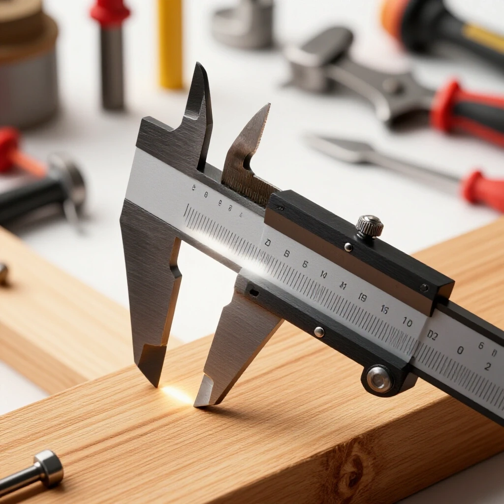
Scaling a shop requires a shift in mindset from “making things” to “manufacturing parts.” This involves a deep dive into layout physics, electrical infrastructure, and the integration of precision tools that ensure consistency across every piece of metal that leaves your bench. One of the most effective ways to bridge the gap between manual labor and automated precision is through the use of mechanical depth indexing for calipers. This simple, shop-made modification allows for consistent material removal and part positioning without the need for complex, one-off jigs for every new task.
Optimizing Material Flow and Precision Benchmarks
Material flow is the strategic movement of raw stock through various stages of fabrication to minimize handling and maximize throughput. A well-planned layout treats the shop floor as a circuit where metal enters at one point and exits as a finished product with the least amount of backtracking possible.
When I first audited my shop layout, I used what we call a “spaghetti diagram.” I tracked my physical steps for a single project and found that I was walking nearly two miles a day just to move between the saw, the bench, and the welder. For an advanced shop owner, this is a massive bottleneck. You want a linear or U-shaped flow. Raw stock should land near your primary cutting station—often a CNC plasma table or a heavy-duty bandsaw. From there, it should move to deburring, then to precision machining or bending, and finally to the welding and finishing stations.
To maintain precision during these transitions, I rely on adjustable measurement references. When you are batch-processing parts on a manual mill or a bandsaw, you cannot afford to reset your measurements for every cut. By using a mechanical stop attached to your calipers, you create a physical limit that ensures every part is indexed to the exact same depth or length. This reduces the cognitive load on the operator and virtually eliminates the “measure twice, cut once” mantra in favor of “set once, cut many.”
| Layout Element | Hobbyist Setup | Advanced Professional Setup | Efficiency Gain |
|---|---|---|---|
| Material Storage | Vertical leaning/Floor piles | Cantilever racking near entry | 40% reduction in handling |
| Machine Zoning | Grouped by power outlets | Grouped by process flow | 25% faster throughput |
| Measurement | Tape measure and scribe | Caliper stops and CNC indexing | 0.001″ consistency |
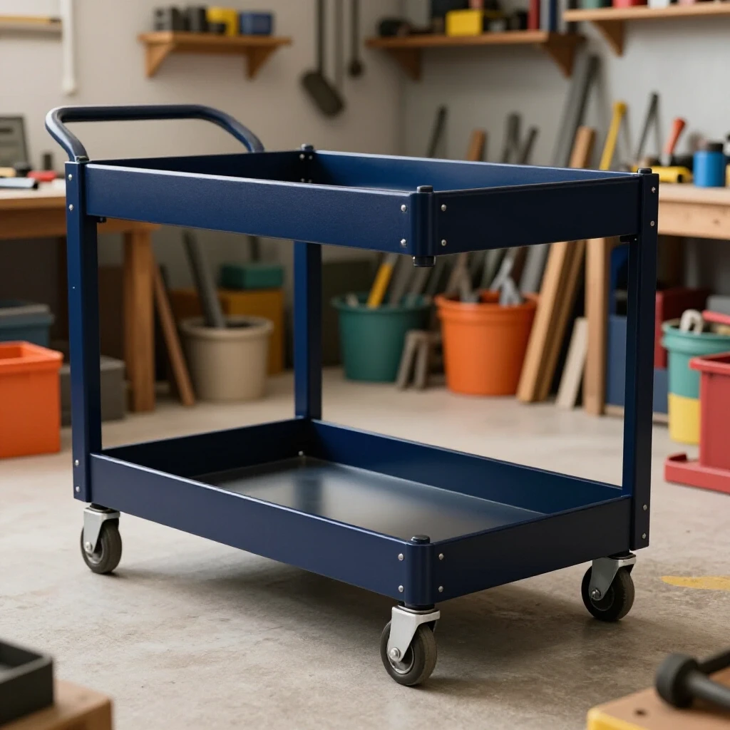
| Scrap Management | Under-bench bins | Dedicated mobile hoppers | 15% cleaner floor space |
Powering the Professional Grade Workshop
Reliable power delivery is the backbone of any scaling fabrication shop, often requiring a move from standard residential service to 3-phase capabilities. This involves calculating total load requirements and choosing between utility service upgrades or the installation of a rotary phase converter to run industrial machinery.
Most of the heavy hitters in a professional shop—large air compressors, industrial mills, and high-amperage welders—perform better on 3-phase power. In my shop, I opted for a rotary phase converter. Unlike a static converter, which only provides a starting pulse, a rotary converter creates a true third leg of power, allowing motors to run at 100% of their rated horsepower. When you are integrating CNC machinery, clean and balanced power is non-negotiable. If your voltages are out of balance by more than 5%, you risk overheating your motors and frying sensitive control electronics.
I recommend keeping a phase-balancing log. Check the voltage between all three legs (L1-L2, L2-L3, and L1-L3) while the machines are under load. This data-driven approach prevents unexpected downtime. If you are scaling, consider a 200-amp subpanel dedicated solely to your fabrication equipment. This isolates your machinery from the rest of the building’s electrical noise, which is critical when running high-frequency start plasma cutters that can interfere with computer-controlled systems.
- Rotary Phase Converter: Best for CNC and high-torque applications.
- Static Phase Converter: Only suitable for light-duty manual machines; reduces power by 1/3.
- Digital Phase Converter: The most expensive option, but provides the cleanest power for sensitive electronics.
Managing Air Quality in High-Output Metal Fabrication
Industrial-grade air management involves the systematic removal of fine metallic dust and hazardous fumes through high-volume filtration and strategic duct design. This process requires calculating the required Cubic Feet per Minute (CFM) for each tool and maintaining proper static pressure throughout the system.
When I integrated my CNC plasma table, the fume issue became an immediate priority. A plasma cutter generates a massive amount of particulate matter that can settle on every surface in your shop, including your precision measuring tools. I designed a multi-stage filtration system that starts at the source. For the plasma table, a water tray or a high-velocity downdraft table is essential. A downdraft system typically requires at least 1,000 to 2,000 CFM to be effective, depending on the table size.
Duct design is where most fabricators fail. I see many shops using 4-inch flexible dryer venting, which is a disaster for airflow. I moved to 6-inch rigid spiral ducting. Every 90-degree bend in your ductwork adds “equivalent feet” of resistance, increasing the static pressure your blower must overcome. To keep metal dust moving and prevent it from settling in the pipes, you need a transport velocity of at least 4,500 feet per minute (fpm). If the air moves too slowly, the dust drops out of suspension, eventually clogging the system and creating a fire hazard.
- Calculate Total CFM: Identify the machine with the highest air requirement.
- Size the Main Trunk: Ensure the main duct can handle the combined CFM of the tools you plan to run simultaneously.
- Install Blast Gates: Use metal blast gates at every drop to direct suction only where it is needed.
- Filter Selection: Use HEPA-rated filters or a cyclone separator to remove 99% of particles before the air returns to the shop.
Integrating CNC Plasma Systems into the Production Line
The integration of CNC automation into a manual workflow requires a balance between software-driven precision and the physical realities of machine gantry alignment and material leveling. This process involves calibrating the X, Y, and Z axes to ensure that digital designs translate accurately to physical metal cuts.
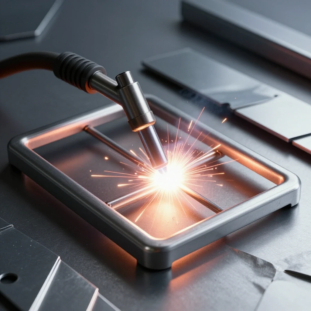
When you bring a CNC plasma table into the mix, you aren’t just buying a tool; you are adding a new employee that never gets tired but requires perfect instructions. The biggest hurdle I faced was the learning curve of CAD/CAM software. You have to think about “kerf compensation”—the width of the material the plasma torch removes. If your software isn’t calibrated to your specific torch and tip size, your parts will be consistently undersized.
Leveling the gantry is another critical step. If the gantry is not perfectly square to the frame, every part you cut will be skewed. I use a large framing square and a set of precision calipers to verify the machine’s travel over a 24-inch distance. If the machine thinks it moved 24 inches but it actually moved 24.062, your bolt holes will never line up. This is where the marriage of manual precision and automation happens. Even with a CNC, you still need manual measurement tools to verify the first article of every production run.
Implementing Mechanical Caliper References for Consistency
A mechanical caliper reference is a shop-made attachment that locks onto the beam of a vernier or digital caliper to provide a repeatable physical stop for depth or length measurements. This DIY fix allows a fabricator to use their caliper as a precision jig, ensuring that multiple parts are positioned or cut with identical dimensions.
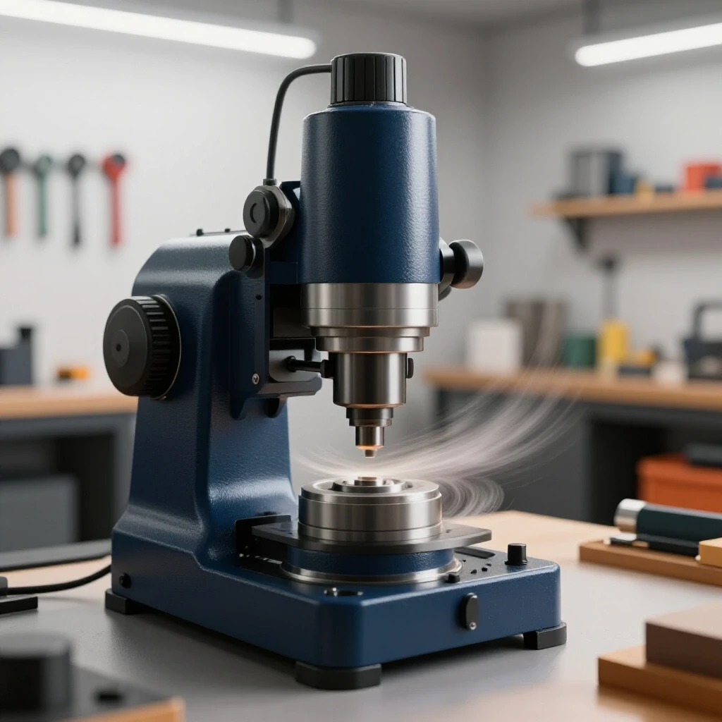
In my shop, I often need to mill a series of slots to a specific depth or cut several pieces of rod to the exact same length. While I could use the machine’s built-in dials, those are prone to backlash and operator error over long runs. Instead, I fabricated a simple stop block out of a small piece of 6061 aluminum. This block features a precision-milled slot that fits snugly over the caliper beam and a thumb screw to lock it in place.
By sliding the stop block to a specific measurement on the caliper and locking it, I can use the face of the block as a reference point. For example, if I need to check the depth of a bore repeatedly, I can set the caliper to the target depth, lock the stop block against the caliper body, and then use it as a “go/no-go” gauge. This is a classic lean manufacturing technique: it standardizes the measurement process and removes the need for the operator to read the fine scale every single time.
- Material Choice: Use aluminum or mild steel for the stop block to prevent marring the hardened stainless steel of the caliper beam.
- Locking Mechanism: A brass-tipped set screw is ideal as it provides a firm grip without scratching the measurement scale.
- Alignment: Ensure the face of the stop block is perfectly perpendicular to the caliper beam to maintain accuracy.
Scaling Throughput with Standardized Measurement Jigs
Standardized measurement jigs are dedicated tools or modifications that eliminate variability in the fabrication process by providing fixed reference points for common operations. These tools are essential for micro-manufacturers who need to maintain high quality while increasing the speed of production.
As I moved toward a more professional operation, I realized that the time I spent “fiddling” with measurements was my biggest profit killer. I began creating a library of jigs for my most common tasks. The caliper stop was the first, but it led to others, like fixed-distance fence stops for my bandsaw and magnetic centering jigs for the drill press.
The goal is to reach a state where the measurement is “baked into” the setup. If you have to think about where the cut starts, you’re losing money. By using a caliper with a locked mechanical reference, you can quickly verify part dimensions during a run without stopping the machine. This allows for real-time quality control. If the part doesn’t fit the preset gap on your caliper jig, you know immediately that your tool offset or machine positioning has drifted.
- Identify Repetitive Tasks: Look for any measurement you make more than five times a day.
- Design a Fixed Reference: Can a caliper stop or a fixed block replace the need for a tape measure?
- Document the Setup: Keep a log of the measurements used for specific parts so you can recreate the setup in months or years.
Case Study: The Evolution of a Production Cell
I recently helped a fellow fabricator reorganize his shop. He was struggling with a 15% reject rate on a custom line of metal furniture legs. We analyzed his workflow and found that his manual marking process was the culprit. He was using a scribe and a ruler for every single piece.
We implemented three major changes. First, we moved his saw closer to the material rack to reduce fatigue. Second, we installed a simple rotary phase converter so he could use a more powerful, consistent cold saw. Finally, we built him a set of adjustable caliper attachments for his depth and length checks. By locking in his measurements at the start of the shift, he reduced his reject rate to less than 2%. His setup time dropped from twenty minutes per batch to less than five. This wasn’t a high-tech “magic” fix; it was the application of basic lean principles and better measurement systems.
Actionable Framework for Shop Optimization
To move your shop toward a more professional, high-output model, follow this systematic approach to your layout and tooling:
- Audit Your Movement: Spend one day recording every time you walk across the shop. Identify the “hot zones” where you spend the most time and move those tools closer together.
- Balance Your Power: If you’re running 3-phase equipment, use a multimeter to check your leg-to-leg voltages. Aim for a balance within 2-5% to protect your motors.
- Seal Your Air System: Use foil tape on all duct joints. A 10% leak in your ductwork can lead to a 30% drop in suction at the tool.
- Standardize Your Measuring: Build a set of mechanical references for your calipers. Use them to verify CNC outputs and manual cuts.
- Track Your Amortization: Keep a spreadsheet of your major equipment costs. Divide the cost of the machine by the number of parts it produces to understand your true overhead.
The path to a professional shop is paved with small, incremental improvements. By focusing on the physics of your layout, the stability of your power, and the repeatability of your measurements, you can scale your operations without losing the quality that built your reputation in the first place.
FAQ: Precision Measurement and Shop Scaling
How does a mechanical stop on a caliper improve repeatability compared to a standard jig? A mechanical stop on a caliper is more versatile than a fixed jig. While a jig is usually built for one specific part, an adjustable stop allows you to turn your caliper into a custom-sized gauge for any dimension. This provides the precision of a dedicated jig with the flexibility of a hand tool.
What is the best material for making a DIY caliper attachment? I recommend 6061 aluminum. It is easy to machine, holds a thread well for the locking screw, and is softer than the stainless steel of the caliper. This ensures that the attachment won’t scratch or damage the precision-ground surfaces of your measuring tool.
Why is 3-phase power so important for CNC machinery? CNC machines rely on steady, consistent power for their stepper or servo motors. 3-phase power provides a more constant delivery of energy compared to the “pulsing” nature of single-phase power. This results in smoother motor operation, less heat, and higher torque, which are all critical for precision cutting.
How do I calculate the CFM needed for my dust collection? Start with the manufacturer’s recommendation for your largest tool. Generally, a small mill or saw needs about 400-600 CFM, while a CNC plasma table or large sander may need 1,000 to 2,000 CFM. Always account for static pressure loss from your ductwork when choosing a blower.
Can I use a caliper stop for both internal and external measurements? Yes, depending on how you design the attachment. Most fabricators design the stop to work with the external jaws for length or the depth rod for hole depth. If you need repeatable internal measurements, you can create a stop that references the internal nibs of the caliper.
What is “backlash” and how does it affect my measurements? Backlash is the play or “slop” in a mechanical system, such as the lead screws on a manual mill. If you rely on the machine’s dials, backlash can cause errors when you change directions. A caliper-based mechanical reference bypasses the machine’s internal mechanics, providing a direct measurement of the part itself.
How often should I calibrate my CNC plasma table? I recommend a quick calibration check every week if you are running the machine daily. Cut a simple 5-inch square and measure it with your calipers. If it’s off by more than your allowed tolerance (usually 0.005″ to 0.010″ for plasma), you need to adjust your steps-per-inch settings in the software.
What is the most common mistake when scaling a fabrication shop? The most common mistake is growing too fast without fixing workflow bottlenecks. Adding a faster machine to a cluttered, disorganized shop will only create a bigger pile of unfinished work. You must optimize your material flow and measurement systems before you increase your raw cutting speed.
How do I prevent my caliper stop from sliding during use? Use a thumb screw with a large head so you can apply adequate finger pressure. For a more permanent hold, use a brass-tipped set screw and a small hex key. The brass tip will grip the steel beam of the caliper without slipping or marring the surface.
Is a rotary phase converter better than a VFD for a whole shop? A Variable Frequency Drive (VFD) is excellent for controlling the speed of a single motor. However, for a whole shop with multiple machines, a rotary phase converter is more practical. It acts as a local “utility grid,” allowing you to run any 3-phase machine just by plugging it into the 3-phase subpanel.
(This article was written by one of our staff writers, Edward Sinclair. Visit our Meet the Team page to learn more about the author and their expertise.)