Safety Rules When Using High Speed Grinding Wheels (Tips)
I have spent the last 18 years in industrial fabrication bays and machine shops, and if there is one thing I have learned, it is that a machine only talks to you if you know how to listen. I remember a Tuesday morning about a decade ago when a young fabricator was prepping a heavy-duty I-beam for a weld. He was using a nine-inch angle grinder, and the sound changed—a high-pitched whine shifted into a low, rhythmic thrum. Before I could shout for him to kill the power, the wheel disintegrated. A fragment the size of a deck of cards embedded itself in a plywood partition thirty feet away. We were lucky that day, but luck is not a diagnostic strategy.
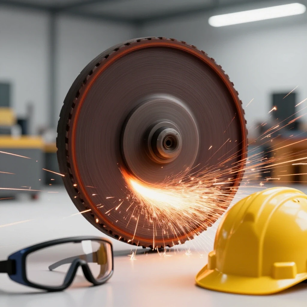
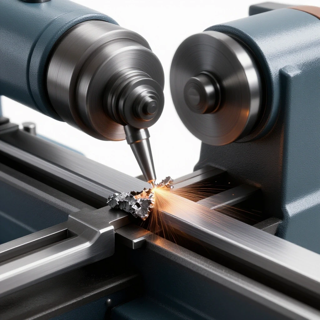
When we deal with high-speed abrasive tools, we are managing immense kinetic energy. A standard grinding wheel can travel at peripheral speeds exceeding 30 meters per second. At those speeds, any mechanical flaw or procedural error becomes a projectile hazard. My goal is to help you move past “guessing” why a tool feels off and move toward a systematic approach to abrasive tool operation. We will look at how to identify structural weaknesses in discs, match equipment specs to consumables, and isolate the root causes of tool chatter that lead to catastrophic failures.
Understanding the Physics of High-Speed Abrasive Rotation
Abrasive rotation physics involves the study of how centrifugal force acts upon a bonded disc as it spins at high revolutions per minute. This section covers the relationship between the wheel’s structural integrity and its ability to withstand the outward pressure generated by high-speed operation.
Centrifugal force is a relentless critic of poor maintenance. When a wheel spins, every grain of abrasive is trying to fly away from the center. The “bond”—the resin or vitrified material holding the wheel together—is the only thing preventing a burst. If the wheel’s rated RPM is lower than the tool’s output, the bond will fail. I always tell my team to check the manufacturer’s stamp on the wheel against the plate on the grinder. If the plate is missing, we use a tachometer to verify the spindle speed.
One common mistake I see is ignoring the “peripheral speed.” While RPM tells you how fast the spindle turns, the peripheral speed tells you how fast the edge of the wheel is moving. A larger wheel at the same RPM as a smaller wheel has a much higher edge speed. This is why you must never “downsize” a tool by removing a guard to fit a larger disc. You are essentially creating a mechanical bomb by exceeding the structural limits of the abrasive bond.
Systematic Inspection for Abrasive Disc Integrity
Abrasive disc integrity refers to the physical soundness of a grinding wheel, ensuring it is free from hairline cracks, moisture damage, or manufacturing defects. This process involves visual and auditory testing to confirm the wheel can safely handle operational stresses.
Before I ever mount a wheel, I perform a “ring test.” This is a simple but effective diagnostic tool for vitrified wheels. You suspend the wheel through its center hole and tap it gently with a non-metallic object, like a screwdriver handle. A sound wheel will produce a clear, metallic ring. If you hear a dull “thud,” the wheel is cracked internally. I don’t care if it looks brand new; a thud means it goes in the scrap bin.
- Visual Inspection Checklist:
- Check for chipped edges or deep gouges in the abrasive surface.
- Look for discoloration, which may indicate oil or moisture contamination.
- Inspect the center metal bushing for looseness or rust.
- Verify the expiration date; the resins in bonded wheels can degrade over time.
Building on this, you must check the blotters—the paper or cardboard discs on either side of the wheel. These aren’t just for labeling. They act as cushions that distribute the flange pressure evenly. If a blotter is torn or missing, the metal flange will press directly onto the abrasive, creating a stress point that often leads to a fracture during the first few seconds of use.
Matching Machine RPM and Spindle Tolerances
Matching machine RPM involves synchronizing the rotational speed of the power tool with the maximum safe operating limit of the abrasive consumable. Proper synchronization prevents the mechanical overstressing of the disc and ensures stable material removal without tool chatter.
In my experience, many “vibration issues” are actually a result of mismatched tolerances between the spindle and the wheel bore. If the hole in the wheel is even 0.005 inches too large, the wheel will sit off-center. This creates an eccentric rotation that produces massive vibration. I’ve seen this mistake lead to premature bearing failure in expensive grinders and, more importantly, uneven wear on the wheel that makes it prone to catching or kicking back.
| Component | Standard Tolerance/Metric | Diagnostic Action |
|---|---|---|
| Spindle Runout | < 0.002 inches | Measure with a dial indicator at the spindle base. |
| Wheel RPM Rating | Must exceed Tool RPM | Compare wheel stamp to tool nameplate. |
| Flange Diameter | At least 1/3 of wheel diameter | Measure to ensure equal pressure distribution. |
| Spindle Nut Torque | Hand tight plus 1/4 turn | Avoid over-tightening which can crush the wheel bond. |
Interestingly, many fabricators overlook the “back-EMF” or voltage drops in their shops. If your grinder is struggling under load, the RPM might drop, causing you to push harder. This increased pressure generates heat, which softens the resin bond of the wheel. Using a multimeter to check for a voltage drop at the outlet can help you determine if your tool is actually receiving the power it needs to maintain its rated speed.
Eliminating Tool Chatter and Resonant Harmonics
Tool chatter is a high-frequency vibration caused by the interaction between the abrasive wheel and the workpiece, often resulting in poor surface finish and mechanical fatigue. Isolating these harmonics requires checking for spindle play, material rigidity, and wheel balance.
When a grinder starts to “bounce” on the metal, most people just grip it tighter. That is a mistake. Chatter is a signal that the system has reached a resonant frequency. This often happens because the workpiece isn’t clamped properly or the wheel has developed a “flat spot.” If you continue to grind during a chatter event, you are micro-fracturing the wheel’s bond.
To troubleshoot this, I first look at the mounting. Is the flange clean? Even a tiny piece of grit between the flange and the wheel can cause the disc to wobble. If the mounting is clean, I check the spindle for backlash. If I can move the spindle side-to-side more than a couple of thousandths of an inch, the bearings are shot. No amount of technique can fix a wheel that is being held by a loose spindle.
- Steps to Isolate Chatter:
- Stop the tool and check the wheel for “loading” (metal bits stuck in the abrasive).
- Ensure the workpiece is clamped as close to the grind site as possible to increase rigidity.
- Adjust your angle of approach; a 15-to-30-degree angle is usually the “sweet spot” for material removal.
- Check for “glazing,” where the abrasive grains have dulled and are rubbing rather than cutting.
Preventing Weld Porosity through Proper Surface Preparation
Weld porosity is a defect characterized by small gas pockets trapped in the weld metal, often caused by contaminants left behind during the grinding process. Effective surface preparation involves using clean, task-specific abrasives to remove oxides without embedding foreign materials.
I’ve seen many fabricators spend hours chasing “electrical gremlins” in their welders when the real problem was their grinding wheel. If you use a wheel that was previously used on aluminum to prep a stainless steel joint, you are pushing contaminants into the grain of the metal. These contaminants vaporize during welding, creating gas bubbles—porosity.
To avoid this, I maintain a strict “one wheel, one material” rule. I also look for wheels with a specialized bond that doesn’t “smear” the metal. Smearing happens when the wheel gets too hot and pushes the surface of the metal over the contaminants rather than cutting them away. If you see a shiny, mirrored finish after grinding, you might actually be trapping oils and oxides underneath a thin layer of moved metal. A proper prep should look clean and slightly matte.
The Role of Flanges and Blotters in Mechanical Safety
Flanges and blotters are the hardware components that secure a grinding wheel to the machine spindle, providing the necessary clamping force and vibration dampening. Their correct alignment and condition are critical for preventing localized stress that could lead to wheel breakage.
The flange is the unsung hero of the grinding world. It must be clean, flat, and of the correct size. I’ve seen people use a mismatched pair of flanges—perhaps a small one on the back and a large one on the front. This creates a “shearing” force on the wheel. Think of it like trying to bend a piece of glass; it might hold for a second, but once it goes, it goes all at once.
- Critical Flange Rules:
- Both flanges must be the same diameter.
- The bearing surfaces must be free of burrs or old abrasive dust.
- Never use a flange that is warped; check it against a machinist’s flat if you are unsure.
- Ensure the “keyway” or flats on the spindle are perfectly aligned with the flange to prevent slipping.
As a result of these mechanical stresses, the blotter acts as a gasket. It compensates for the slight irregularities in the abrasive wheel’s surface. If you are troubleshooting a wheel that keeps coming loose, check if the blotters are compressed unevenly. This usually indicates that the flange is not sitting square to the spindle.
Comprehensive Personal Protection and Workspace Management
Personal protection and workspace management involve the use of specialized gear and environmental controls to shield the operator and bystanders from sparks, debris, and respiratory hazards. This includes using face shields, fire-resistant clothing, and spark-containment barriers.
Safety is not just about what you wear; it’s about how you set up the “kill zone.” When I’m troubleshooting a heavy-duty grinding operation, I always look at the spark stream. Sparks are essentially molten shards of metal and abrasive. If they are hitting a wall and bouncing back, or worse, hitting a pressurized gas cylinder, the shop is a ticking time bomb.
I advocate for a “double-layer” approach to facial protection. Safety glasses are for the small stuff, but a full-face shield is for the catastrophic stuff. If a wheel bursts, safety glasses won’t protect your neck or jaw. Furthermore, I always check the position of the guard. The guard should be positioned between the operator and the wheel, covering at least 180 degrees of the disc. If a fabricator tells me the guard “gets in the way,” I tell them their setup is wrong. You move the workpiece, not the guard.
Troubleshooting Electrical and Motor Controller Faults
Electrical and motor controller faults in grinding equipment refer to issues like current phase unbalance, voltage drops, or faulty capacitors that cause a tool to lose torque or overheat. Diagnosing these requires measuring resistance and monitoring power draw under load.
Sometimes the “vibration” you feel isn’t mechanical—it’s electrical. In three-phase industrial grinders, if one phase is slightly weak, the motor will “stutter” under load. This creates a rhythmic pulse that feels exactly like an unbalanced wheel. I use a clamp-on ammeter to check the draw on all three legs while the tool is running. If the readings vary by more than 5-10%, we have a motor or supply issue.
For single-phase tools, the most common culprit is the cord. A frayed cord or a loose connection in the plug creates intermittent resistance. This causes the motor to hunt for speed, which in turn causes the wheel to bite and release unevenly. This “hunting” is a major cause of kickback, as the operator cannot predict the tool’s torque output at any given second.
Advanced Diagnostic Tools for Modern Fabrication
Modern diagnostic tools include digital technology such as smartphone vibration spectrum analyzers and infrared heat trackers that provide real-time data on machine performance. These tools allow fabricators to identify subtle issues before they lead to equipment failure or injury.
We have moved past the days of just “feeling” the vibration. Today, I use a smartphone app that utilizes the phone’s internal accelerometer to map vibration frequencies. By placing the phone on the tool housing (while the tool is off and the wheel is being spun by hand or at low speed), I can see if the vibration is a 1x frequency (unbalanced wheel) or a much higher frequency (bearing failure).
- Essential Diagnostic Kit:
- Digital Calipers (to check wheel thickness and bore).
- Infrared Thermometer (to monitor gearbox and workpiece temperature).
- Tachometer (to verify spindle RPM).
- Vibration Spectrum Analyzer (app or dedicated tool).
- Feeler Gauges (to check guard-to-wheel clearance).
Using an infrared thermometer is particularly helpful when troubleshooting why wheels are wearing out too fast. If the workpiece is hitting 500 degrees Fahrenheit during a simple cleaning pass, the operator is using too much pressure or the wheel grade is too hard for the material. Heat is the enemy of the bond, and tracking it helps you adjust your technique before the wheel fails.
Establishing a Systematic Maintenance and Safety Log
A maintenance and safety log is a structured record-keeping system used to track tool inspections, wheel changes, and repair histories. This documentation helps identify recurring issues and ensures that all equipment meets safety standards before use.
In a busy shop, memory is a poor substitute for a logbook. I keep a simple spreadsheet for every major piece of grinding equipment. We track when the bearings were last greased, when the flanges were inspected for flatness, and any incidents of wheel breakage. If I see that a specific machine has broken three wheels in a month, I don’t blame the wheels—I pull the machine for a full spindle and alignment teardown.
This data-driven approach removes the emotion from troubleshooting. Instead of getting frustrated, you look at the numbers. If the RPM is stable, the flanges are flat, and the wheels are stored in a dry environment, but you still have issues, you start looking at the operator’s feed rate or the material’s metallurgical properties. It’s about narrowing the field of variables until only the truth remains.
Frequently Asked Questions
How do I know if my grinding wheel is spinning too fast for the machine? Check the maximum RPM printed on the wheel’s blotter or stamped on the center. Compare this to the “No Load RPM” listed on the tool’s nameplate. The wheel’s rating must always be equal to or higher than the tool’s maximum speed. If the tool lacks a label, use a handheld tachometer to measure the spindle speed before mounting any abrasive.
What is the “ring test” and can I use it on all wheels? The ring test is used for vitrified (ceramic-bonded) wheels. Suspend the wheel and tap it with a light, non-metallic tool. A clear ring indicates a solid bond, while a dull thud suggests an internal crack. This test does not work for organic-bonded wheels (like rubber or resinoid) or small diameter wheels, as they do not resonate the same way.
Why does my grinder vibrate even with a brand-new wheel? Vibration usually stems from one of three sources: an off-center wheel (bore size mismatch), a warped flange, or worn spindle bearings. Use a dial indicator to check the spindle for runout. If the spindle is true, ensure the flanges are clean and the wheel blotters are intact. Even a tiny piece of debris can cause a wheel to sit at an angle.
Can I use a grinding wheel that has been dropped if it looks okay? No. Even if there are no visible chips, a drop can cause internal micro-fractures in the bond. Under the high centrifugal force of operation, these fractures can expand instantly, leading to a “wheel burst.” The cost of a new wheel is negligible compared to the risk of injury.
What is the correct way to tighten a grinding wheel nut? The nut should be “snug.” Over-tightening is a common mistake that can crush the abrasive grains or distort the flanges. Tighten the nut firmly by hand or with the provided wrench just enough to prevent the wheel from slipping. The rotation of the spindle during use is often designed to keep the nut seated.
How does wheel “loading” affect safety? Loading occurs when bits of soft metal (like aluminum or copper) get trapped in the wheel’s pores. This makes the wheel surface smooth, which leads to “rubbing” instead of “cutting.” The resulting friction generates extreme heat, which can weaken the wheel’s bond and cause the tool to kick back as it struggles to bite into the material.
What is the purpose of the paper blotter on the side of the wheel? The blotter serves two main roles: it provides a uniform gripping surface for the flanges and acts as a cushion to distribute clamping pressure. It also helps to absorb slight vibrations and protects the flanges from being abraded by the wheel. Never mount a wheel that has missing or heavily damaged blotters.
Is a face shield enough protection for high-speed grinding? A face shield is essential, but it must be worn over safety glasses or goggles. The glasses protect against fine dust and small sparks that can fly under the shield, while the shield provides the primary impact protection if a wheel disintegrates or a large piece of debris is ejected.
How often should I inspect the guards on my grinding equipment? Inspect guards daily before use. Look for cracks in the metal, loose mounting bolts, or signs of thinning from internal spark erosion. The guard should be adjusted so that it is always between you and the wheel, and the gap between the tool rest and the wheel (on bench grinders) should be no more than 1/8 inch.
Can I use a wheel if the expiration date has passed? It is not recommended. The resins used in bonded wheels are organic compounds that can degrade over time, especially in humid or high-temperature environments. An expired wheel may have a weakened bond that cannot safely withstand the rated centrifugal forces.
Why is my workpiece turning blue or black while grinding? Discoloration is a sign of excessive heat, often caused by using a wheel that is too “hard” for the material or by applying too much pressure. This heat can cause the metal to lose its temper (soften) and can also lead to thermal cracking in the grinding wheel itself. Lighten your pressure and ensure you are using the correct grit and bond for the job.
What should I do if a wheel breaks during operation? Immediately turn off the power and unplug the tool. Do not move the tool until the spindle has stopped completely. Inspect the guard, flanges, and spindle for damage. You must also inspect the machine’s bearings, as the sudden imbalance of a breaking wheel can bend the spindle or shatter a bearing race. Document the incident to identify if a specific batch of wheels or a machine fault was the cause.
(This article was written by one of our staff writers, Paul Whitaker. Visit our Meet the Team page to learn more about the author and their expertise.)