Shop Tool Upgrades That Improve Fabrication Accuracy (Tips)
I have spent the last 17 years in the grease and grit of industrial maintenance. My hands have been inside everything from massive vertical boring mills to the benchtop lathes found in home garages. During that time, I have learned that a shiny coat of paint often hides a multitude of mechanical sins. Many fabricators buy a machine based on a brand name or a spec sheet, only to find it chatters during a light cut or loses its squareness after a month of use.
The reality of the tool market is that marketing teams focus on horsepower and flashy digital displays. As a maintenance specialist, I focus on the “bones” of the machine. I look at the grain of the cast iron, the grade of the spindle bearings, and the thickness of the bedways. If the foundation is weak, no amount of careful operation will result in a precise part. In this guide, I will share the technical markers I use to evaluate equipment and the specific physical modifications that can turn a mediocre tool into a precision instrument.
Evaluating the Structural Integrity of Machine Bases
The frame of a metalworking tool must resist the forces of cutting without flexing or vibrating. A rigid base ensures that the tool bit stays exactly where you intended, preventing the “chatter” marks that ruin surface finishes. High-quality machinery uses heavy castings to absorb energy and maintain alignment over years of heavy use.
Why Heavy Castings Dampen Harmonics
Cast iron is the preferred material for machine frames because of its internal structure. It contains graphite flakes that act as tiny shock absorbers, soaking up the vibrations created by a spinning cutter. When evaluating a machine, the weight-to-work-envelope ratio is often more important than the motor’s peak horsepower rating.
- Class 25/30 Gray Iron: This is the standard for most mid-range machinery. It offers decent dampening but can be prone to internal stresses if not seasoned properly.
- Meehanite Castings: This is a licensed process that ensures a very uniform grain structure. If a machine lists Meehanite, it usually indicates a higher level of structural stability.
- Dampening Capacity: Cast iron dampens vibrations roughly ten times better than steel and thirty times better than aluminum. This is why a light, sheet-metal stand will often make a lathe perform worse than if it were bolted to a solid bench.
| Material Type | Vibration Dampening Capacity | Tensile Strength (PSI) | Common Use Case |
|---|---|---|---|
| Gray Iron (Class 25) | High | 25,000 | Benchtop Lathe Beds |
| Gray Iron (Class 40) | High | 40,000 | Industrial Mill Columns |
| Fabricated Steel | Low | 60,000 | Budget Saw Frames |
| Ductile Iron | Moderate | 60,000+ | High-Stress Brackets |
Assessing Spindle Quality and Bearing Design
The spindle is the heart of any rotating tool, whether it is a mill, a lathe, or a drill press. It must rotate on a perfect axis without any side-to-side or up-and-down movement. Upgrading the bearings or adjusting the “preload” can significantly tighten the tolerances of a machine that feels “loose” during operation.
Understanding Total Indicated Runout (TIR)
Total Indicated Runout, or TIR, is a measurement of how much a shaft wobbles as it rotates. You measure this by placing a dial indicator against the inside of the spindle taper and rotating it by hand. For high-precision work, you want to see a deviation of less than 0.0005 inches.
- Radial Runout: This is the “side-to-side” wobble. It causes tools to cut slightly larger holes than intended and leads to uneven tool wear.
- Axial Runout: This is the “in-and-out” movement. It is particularly damaging to milling cutters, as it causes one tooth to take a much deeper bite than the others.
- Bearing Preload: This is the process of applying a permanent load to the bearings to remove internal clearance. Properly set preload ensures the spindle does not shift when the cutting tool hits the metal.
Choosing Between Bearing Types
Not all bearings are created equal. The type of bearing used in a spindle determines its maximum speed and its ability to handle heavy cuts. When I teardown a machine, I look for the specific arrangement of these components to judge its true capability.
- Tapered Roller Bearings: These are excellent for lathes because they handle both radial and thrust loads very well. They are robust but generate more heat at high speeds.
- Angular Contact Ball Bearings: These are standard in high-speed milling spindles. They are very precise and run cool, but they are more sensitive to “crashes” than roller bearings.
- Deep Groove Ball Bearings: Often found in budget drill presses. These are not designed for the side-loading seen in milling and will fail or lose accuracy quickly if pushed.
Enhancing Motion Control with Better Drive Systems
The way a motor delivers power to the spindle affects the surface finish of your workpiece. Traditional single-phase motors pulse 60 times per second, which can leave subtle patterns in soft metals. Upgrading to a three-phase motor controlled by a Variable Frequency Drive (VFD) provides much smoother power delivery.
The Shift to Variable Frequency Drives (VFD)
A VFD takes standard household power and converts it into a “clean” three-phase signal. This allows you to change the motor speed by turning a dial rather than swapping greasy belts. More importantly, it allows for “constant torque,” meaning the machine doesn’t bog down as easily at low speeds.
- Vibration Reduction: Three-phase motors are inherently more balanced than single-phase motors, leading to less “ghosting” on the metal surface.
- Braking Control: Most VFDs allow you to set a DC injection brake, which stops the spindle almost instantly. This is a major safety and productivity boost.
- Soft Start: This feature slowly ramps the motor up to speed, reducing the mechanical shock on the gears and belts.
Evaluating Motor Horsepower and Torque
Don’t be fooled by “Peak HP” ratings often found on budget equipment. Look for the “Continuous Duty” or “S1” rating. A 1.5 HP motor that can run all day is far more valuable than a 3 HP motor that overheats after twenty minutes of heavy hogging. In my experience, a high-quality brushless DC motor can often outperform a larger induction motor because it maintains its torque throughout the entire RPM range.
Improving Accuracy through Slide and Way Modifications
The “ways” are the tracks that the different parts of a machine slide on. If these tracks are not perfectly flat or if there is too much “slop” in the fit, the machine will not cut straight. Adjusting the “gibs”—the metal strips that take up the slack in the slides—is one of the most effective ways to improve performance.
Eliminating Backlash in Lead Screws
Backlash is the “dead space” you feel when you turn a handwheel and the table doesn’t move. It happens because there must be a small gap between the screw threads and the nut for them to turn. While you can work around backlash, reducing it makes the machine much more predictable.
- Split Nuts: Many manual machines use a nut that can be tightened to pinch the screw, reducing the gap.
- Ball Screws: These use recirculating ball bearings instead of sliding threads. They are nearly frictionless and have almost zero backlash, but they are expensive to retrofit.
- Acme Screws: These are the standard “square” threads. They are durable and can handle heavy loads, but they will eventually wear and develop more play.
The Importance of Way Lubrication
Metal-on-metal sliding creates friction and heat. If the ways run dry, they will “gall,” which means the metal starts to tear and weld itself together. I always look for machines with a “one-shot” lubrication system. This is a pump that sends oil to every sliding surface and lead screw at once. It ensures that the machine moves smoothly and that the precision-ground surfaces stay that way for decades.
Implementing Digital Readouts for Real-World Precision
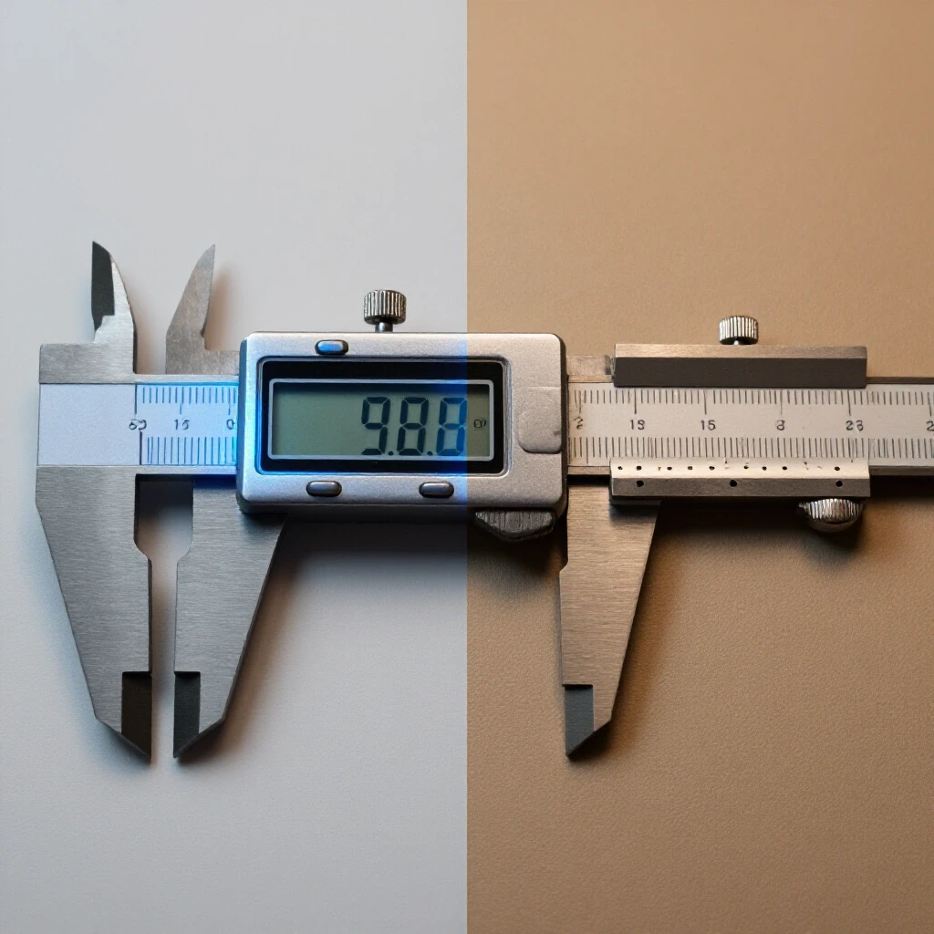
A Digital Readout (DRO) is a system of sensors and a display screen that tells you exactly where the machine table is located. It bypasses the errors found in lead screws and handwheel dials. Installing a DRO is often the single most impactful upgrade a fabricator can make to a manual machine.
Choosing Between Glass and Magnetic Scales
There are two main types of sensors used for DROs. Each has its own strengths depending on the environment of your shop.
- Glass Scales: These use an optical sensor to read lines etched on a glass bar. They are extremely accurate but can be sensitive to coolants and oils if the seals fail.
- Magnetic Scales: These use a magnetic strip and a sensor head. They are much more resistant to dirt and fluids. They can also be cut to length, making them easier to install on non-standard machine sizes.
- Resolution: Most shop-grade DROs offer a resolution of 5 microns (0.0002 inches) or 1 micron (0.00004 inches). For most manual work, 5-micron scales are more than sufficient and less “jittery” to use.
| Feature | Glass Scales | Magnetic Scales |
|---|---|---|
| Accuracy | Very High | High |
| Durability | Moderate (Fragile) | Very High |
| Contamination Resistance | Moderate | High |
| Ease of Installation | Standard | High (Cut-to-fit) |
| Price | Mid-Range | Slightly Higher |
Alignment Procedures and Testing Tools
Even the best machine will produce poor results if it is not leveled and aligned. Gravity can actually twist a heavy iron casting over time if it is not supported correctly. I use a specific set of tools to verify that a machine is ready for precision work.
- Precision Machinist’s Level: This is not a carpenter’s level. It is sensitive enough to show a 0.0005-inch rise over 10 inches. You use this to ensure the machine bed is not twisted.
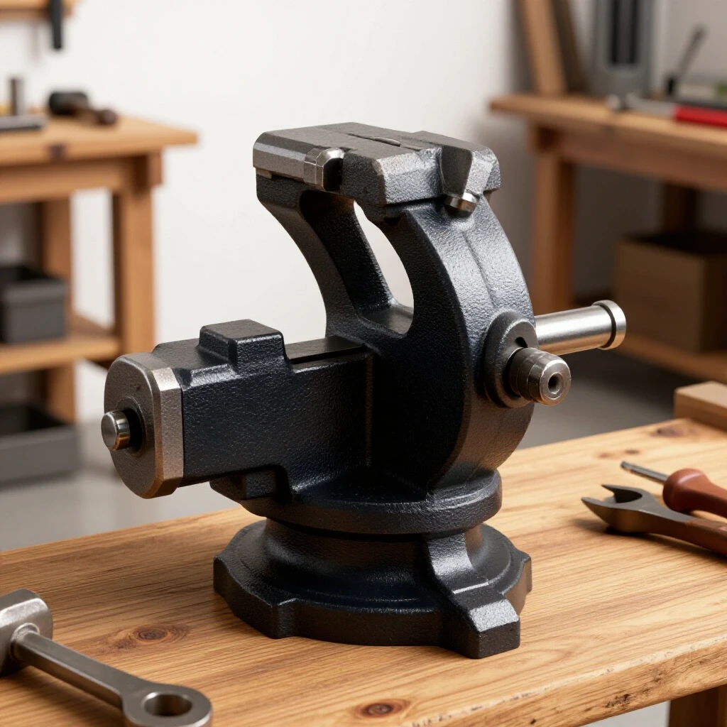
- Test Indicators: These are used to “sweep” a spindle or check the squareness of a vise. A 0.0005-inch graduation is the standard for most setup work.
- Test Bars: These are precision-ground cylinders that you put into a lathe chuck or mill spindle. By running an indicator along the bar, you can see if the spindle is pointing exactly parallel to the ways.
Common Alignment Mistakes to Avoid
A frequent error I see is bolting a machine down to an uneven concrete floor. The force of the bolts can actually pull a twist into the bed of a lathe. Always use leveling feet or shims to get the machine perfectly level before tightening any floor anchors. Another mistake is trusting the factory “zero” marks on swiveling heads or tailstocks. Always verify these with a dial indicator before starting a project that requires tight tolerances.
Planning for Maintenance and Parts Availability
A machine is an investment that should last a lifetime, but parts do wear out. Before buying, I always check how easy it is to source replacement bearings, belts, and nuts. Many budget “off-brand” machines use proprietary parts that are impossible to find three years later.
- Standardized Bearings: Look for machines that use standard ISO or ABEC-rated bearings. You can buy these from any industrial supply house.
- Gearing Materials: Steel gears are loud but durable. Plastic or nylon gears are quiet and act as a “mechanical fuse” to protect the motor, but they will eventually strip. Ensure you can buy spares.
- Electrical Components: Avoid machines with “all-in-one” proprietary circuit boards. It is much better to have a machine with a standard motor and a separate, replaceable VFD or speed controller.
The True Cost of Shipping and Setup
When comparing prices, remember that a 1,500-pound machine requires specialized equipment to move. I have seen many machines damaged because a buyer tried to move them with an undersized pallet jack. Factor in the cost of a lift-gate delivery or a local rigging service. Also, inspect the machine immediately upon arrival for any “hidden” cracks in the castings that might have occurred during transit.
Practical Next Steps for the Decisive Buyer
If you are looking to improve your shop’s capabilities, start with the foundation. Don’t buy a light, fast machine if you need to cut steel. Look for mass, look for quality castings, and look for a spindle that runs true. Once the machine is in your shop, spend the time to level it and dial in the alignments.
If you already own a machine and want better results, the most effective path is: 1. Level the machine using a precision machinist’s level. 2. Install a DRO to eliminate lead screw error. 3. Adjust the gibs to remove play in the slides. 4. Upgrade to a VFD for smoother power and better speed control.
These steps don’t require a massive budget, but they do require a commitment to mechanical detail. In the world of metalworking, precision is earned through careful adjustment and a deep understanding of how your machinery actually works.
Frequently Asked Questions
How can I tell if a machine has high-quality cast iron? Look at the unpainted surfaces of the casting. High-quality iron will have a very fine, consistent grain. If you see large pits, “sand holes,” or evidence of heavy body filler under the paint, it suggests a lower-grade casting. You can also perform a “ring test” by tapping the casting with a small hammer; a solid, high-quality casting will produce a clear, sustained ring rather than a dull thud.
Is a heavier machine always more accurate? Weight provides stability and dampening, but it doesn’t guarantee accuracy. A heavy machine with poorly ground ways or cheap bearings will still produce inaccurate parts. However, a heavy machine provides a better foundation for you to perform upgrades, whereas a light machine is limited by its own lack of rigidity.
What is the most common cause of spindle runout? In new machines, it is often due to poor assembly or low-quality bearings. In used machines, it is usually caused by a “crash” where the tool hit the workpiece too hard, or by a lack of lubrication that caused the bearing races to pit. Sometimes, what looks like spindle runout is actually just dirt or a burr inside the spindle taper.
Can I convert a single-phase machine to a VFD? No, a VFD only works with three-phase motors. To use a VFD, you must replace your existing single-phase motor with a three-phase motor of the same frame size. This is a very common upgrade because it provides better torque and smoother operation.
How much backlash is acceptable in a manual machine? For a brand-new machine, you should expect less than 0.005 inches of backlash. On older, well-used equipment, 0.015 to 0.020 inches is common. While you can compensate for backlash by always approaching your measurement from the same direction, anything over 0.025 inches usually indicates that the lead screw or nut needs to be replaced or adjusted.
What is the difference between a 5-micron and a 1-micron DRO? A 5-micron DRO displays movements in increments of 0.0002 inches. A 1-micron DRO displays increments of 0.00004 inches. For most manual machining, 5 microns is plenty. A 1-micron display can be frustrating to use because the last digit will “flicker” due to tiny vibrations or temperature changes in the shop.
Do I really need a machinist’s level to set up my lathe? Yes. A standard construction level is not accurate enough to detect the tiny twists in a machine bed that cause “taper” (where the lathe cuts a different diameter at one end of the part than the other). A twist of just a few thousandths of an inch over the length of the bed can significantly affect your accuracy.
What is “bearing preload” and why does it matter? Preload is a slight “squeeze” applied to the bearings during installation to remove any internal play. Without preload, the spindle would move slightly every time the cutting tool touched the metal, leading to chatter and poor dimensions. Too much preload, however, causes friction and will burn out the bearings.
Are magnetic scales better than glass scales for a messy shop? Generally, yes. Magnetic scales are much more “forgiving” of oil, coolant, and metal chips. Glass scales are very accurate but rely on an optical eye that must stay clean. If you do a lot of heavy milling with flood coolant, magnetic scales are usually the safer investment.
How often should I lubricate my machine’s ways? You should lubricate the ways every time you use the machine. If you have a one-shot oiler, give it a pump before you start and again every few hours of operation. If you are oiling by hand, ensure there is a visible film of oil on the tracks at all times. Dry ways are the leading cause of permanent precision loss in workshop tools.
(This article was written by one of our staff writers, Steven Brooks. Visit our Meet the Team page to learn more about the author and their expertise.)