How to Weld Thin Wall Tubing Without Burn-Through (Tutorial)
In my 14 years as a mechanical engineer and shop floor inspector, I have seen the same scene play out dozens of times. A fabricator stands over a project, the smell of ozone in the air, staring at a jagged, glowing hole where a clean seam should be. This moment of failure usually happens when working with thin-gauge materials like 0.049-inch or 0.065-inch wall tubing. The margin for error is razor-thin, and the stakes are higher than they look. If you overheat the metal, you don’t just get a hole; you compromise the structural integrity of the entire build.
My background in industrial structural verification has taught me that the most dangerous failures are the ones you can’t see immediately. A weld that looks “okay” on the surface but has caused excessive grain growth in the heat-affected zone is a ticking time bomb. This guide is designed to help you navigate the physics of thin-wall metalwork, ensuring your projects are safe, stable, and professionally executed.
Understanding the Physics of Heat in Thin Sections
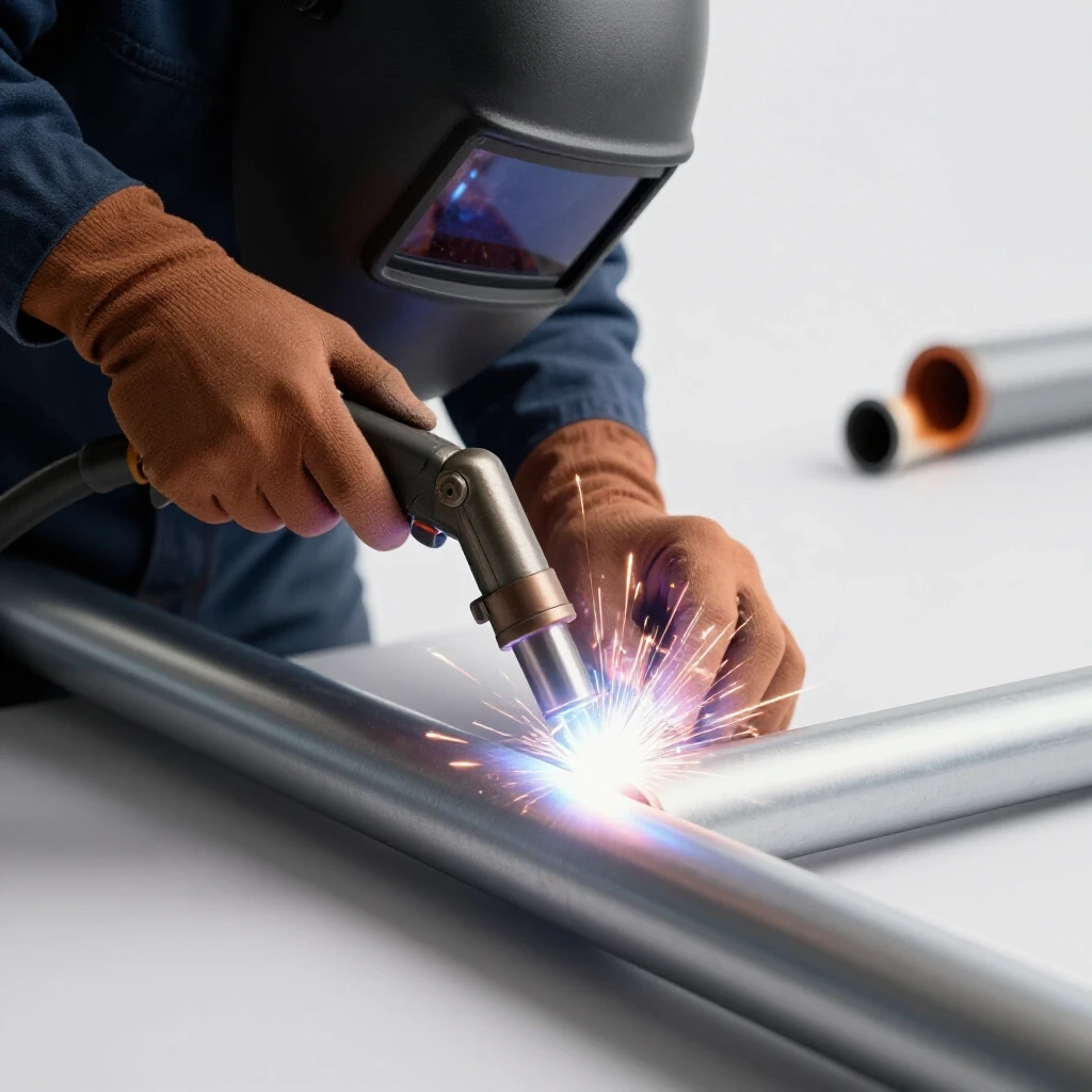
Heat management in thin materials involves controlling the energy input to prevent the base metal from reaching its melting point too quickly. Unlike thick plate, thin walls have less mass to dissipate heat, leading to rapid expansion and potential melt-through. When you apply an arc to a tube with a wall thickness of 1/16th of an inch, the temperature rises almost instantly across the entire cross-section.
In my early days on the shop floor, I learned that the Heat Affected Zone (HAZ) is where most structural failures begin. The HAZ is the area of base metal that did not melt but had its microstructure and mechanical properties altered by the heat. In thin tubing, the HAZ can easily span the entire thickness of the wall. If you linger too long with the torch, you are essentially annealing the metal, making it soft and prone to bending or cracking under load. According to AWS standards, minimizing the width of the HAZ is critical for maintaining the original tensile strength of the alloy.
Material Selection and Load Path Planning
Choosing the right tubing involves matching the wall thickness to the intended mechanical load while considering the fabricator’s skill level. Understanding load paths ensures that the welded joints distribute stress evenly across the structure, preventing localized fatigue or sudden failure. You must think like an engineer before you pick up the torch.
When I design a lightweight frame, I always look at the yield strength of the material, which is the point where the metal permanently deforms. For common 1018 mild steel tubing, this is roughly 53,000 PSI. However, once you weld it, that number can drop significantly near the joint. I recommend a structural safety margin of at least 2:1 for static loads and 4:1 for anything that moves or carries weight.
| Tubing Wall Thickness | Decimal Equivalent | Common Application | Difficulty Level |
|---|---|---|---|
| 20 Gauge | 0.035 in | Lightweight furniture, ductwork | Expert |
| 18 Gauge | 0.049 in | Bicycle frames, exhaust kits | Advanced |
| 16 Gauge | 0.065 in | Go-kart frames, racks | Intermediate |
| 11 Gauge | 0.120 in | Off-road bumpers, heavy frames | Beginner |
Critical Workshop Safety for Thin-Gauge Projects
Safety in thin-wall fabrication extends beyond basic protection to include fire prevention and eye safety from high-frequency arcs. Because these projects often require high precision and close-up work, the environment must be controlled to prevent accidents during delicate maneuvers. A steady hand is impossible if you are worried about a fire or a trip hazard.
I once saw a small shop fire start because a fabricator was so focused on a delicate TIG weld that they didn’t notice sparks landing on a pile of oily rags three feet away. When working with thin materials, you are often using higher-frequency arcs or pulsed settings that can be deceptively bright. I always use a high-quality auto-darkening helmet with a Shade 10-13 filter to prevent “arc eye,” a painful condition similar to a sunburn on the cornea.
Workshop Safety Checklist
- Ensure the welding area is clear of flammables within a 35-foot radius.
- Check that your ventilation system is pulling fumes away from your face, not across the weld.
- Inspect gas hoses for leaks using a soapy water solution to prevent shielding gas waste.
- Verify that your grounding clamp is attached directly to the workpiece or a conductive table.
- Wear flame-resistant (FR) clothing, as thin-wall sparks can easily pierce standard cotton.
Perfecting Joint Fit-Up to Prevent Melt-Through
Fit-up refers to the gap and alignment between two pieces of metal before welding. In thin-wall applications, even a 0.5mm gap can lead to an immediate burn-through, as the arc lacks a sufficient heat sink to bridge the void without destroying the edges. Precision is your best defense against structural failure.
If you have a gap in a joint between two 0.065-inch tubes, the arc will naturally want to jump to the closest edge. This concentrates all the heat on a tiny point of metal that has nowhere to dump that energy. Interestingly, the air in the gap acts as an insulator, making the edges melt even faster. I use a dedicated tubing notcher or a high-quality belt sander to ensure “light-tight” joints. If light can pass through the joint before you weld it, the joint is not ready.
Optimizing Welding Machine Parameters
Machine settings for thin materials require precise control over amperage, voltage, and shielding gas flow. Proper calibration ensures that the arc remains stable at low power levels, providing enough heat to fuse the metal without exceeding its thermal capacity. Guessing your settings is a recipe for wasted material and frustration.
For TIG welding, I generally follow the rule of one ampere per 0.001 inch of metal thickness as a starting point. For 0.065-inch tubing, I set my machine to 65 amps but use a foot pedal to modulate that power. For MIG, the wire speed is the most critical variable. If the wire speed is too low, the arc will burn back into the tip or melt through the tube before a puddle can form.
| Material Thickness | TIG Amperage (Peak) | MIG Wire Speed (IPM) | Shielding Gas Flow (CFH) |
|---|---|---|---|
| 0.035 in | 30-40 A | 140-150 | 12-15 |
| 0.049 in | 45-55 A | 160-170 | 15-18 |
| 0.065 in | 60-70 A | 180-200 | 15-20 |
The Role of Shielding Gas in Thin-Wall Integrity
Shielding gas protects the molten weld pool from atmospheric contamination like oxygen and nitrogen. In thin-wall fabrication, the welding gas flow rate must be perfectly balanced; too little flow causes porosity, while too much flow creates turbulence that sucks in air, leading to a brittle joint.
I typically recommend a flow rate of 15–20 CFH (cubic feet per hour) for most indoor garage fabrication safety. If you are working in a drafty area, you might be tempted to crank up the gas, but this often causes more problems than it solves. Instead, use a gas lens on your TIG torch. A gas lens replaces the standard collet body and uses a series of fine meshes to create a laminar (smooth) flow of gas. This provides much better coverage at lower pressures, which is essential for keeping thin metal cool and clean.
Advanced Techniques for Heat Dissipation
Heat dissipation strategies involve using external tools or specific torch movements to move energy away from the weld zone. This prevents the “heat soak” effect that causes thin tubes to warp or collapse during the final passes of a joint. Think of it as managing a budget; you only have so much “heat currency” to spend before the metal goes bankrupt.
One of the most effective tools in my kit is the copper backing bar. Copper has a much higher thermal conductivity than steel. By placing a copper mandrel or block behind the weld area, you create a path for excess heat to escape. I have also used “heat sink” pastes, but they can be messy and sometimes contaminate the weld. Another technique is the “stitch” method: weld a small section (about 1/2 inch), then move to the opposite side of the tube to let the first section cool. This keeps the overall temperature of the workpiece low and prevents distortion.
Why Weld Porosity Destroys Structural Integrity
Welding porosity consists of tiny gas bubbles trapped in the cooling metal, resembling a sponge. In thin-wall tubing, where the metal is already sparse, porosity can reduce the effective thickness of the joint by 50% or more, leading to sudden, catastrophic failure under vibration or load.
During a failure analysis I conducted on a lightweight trailer, I found that the main support tube had snapped right at the weld. Under a microscope, the cross-section looked like Swiss cheese. The fabricator had failed to clean the mill scale and oil off the tubing before welding. When the arc hit the contaminants, they turned into gas that got trapped in the rapidly freezing puddle. To prevent this, I use a three-step cleaning process: 1. Mechanical removal of mill scale using a clean flapper disc. 2. Chemical cleaning with acetone or denatured alcohol. 3. Handling the parts with clean gloves to avoid skin oils.
Inspecting for Internal Defects and Structural Integrity
Inspection is the process of verifying that a weld is free from cracks, porosity, or undercut. In thin tubing, these defects are particularly dangerous because there is very little material left to support the load if the weld is compromised. You cannot fix what you do not measure.
I always perform a visual inspection using a 10x magnifying glass. I look specifically for “undercut,” which is a groove melted into the base metal right next to the weld toe. In thin tubing, an undercut acts as a “perforation line,” making it incredibly easy for the tube to snap under stress. If I suspect a hidden crack, I use a modern non-destructive testing (NDT) kit, specifically a dye penetrant. You spray a red dye on the weld, wipe it off, and then apply a white developer. If there is a crack, the red dye will “bleed” through the white powder, revealing the defect.
Weld Quality Checklist
- Profile: Is the weld bead slightly convex (bulging out) rather than concave (sinking in)?
- Consistency: Are the “stack of dimes” evenly spaced, indicating a steady travel speed?
- Color: For stainless or chrome-moly, is the weld straw or purple (good) rather than grey or black (overheated)?
- Penetration: If you can see the inside of the tube, is there a small, consistent bead on the interior?
- Undercut: Are the edges of the weld smooth and flush with the tube surface?
Structural Load-Testing and Safety Verification
Before putting a thin-wall project into service, you must verify its capacity through controlled testing. Structural load testing involves applying a known force to the assembly to ensure it behaves as predicted by your design calculations. This is the final gatekeeper for workshop safety.
In the industry, we often use hydraulic presses with calibrated gauges to test prototypes. In a home shop, you can use known weights or a simple lever system. I once built a custom rack for a client and tested it by loading it with 150% of its rated capacity for 24 hours. I measured the deflection (how much it bent) before, during, and after. If the metal doesn’t return to its original shape, you have exceeded the yield strength, and the design must be reinforced.
Common Failures and Corrective Actions
Even with the best preparation, mistakes happen. The key is to recognize them as data points rather than defeats. Throughout my career, I’ve tracked the most common errors in thin-wall fabrication to create a troubleshooting framework.
| Problem | Root Cause | Corrective Action |
|---|---|---|
| Blow-through hole | Travel speed too slow or amps too high | Increase speed; use a pulsing technique. |
| Brittle welds | Excessive heat or lack of gas coverage | Use a gas lens; reduce total heat input. |
| Tubing warping | Unbalanced weld sequence | Weld in small increments on opposite sides. |
| “Suck-back” | Puddle too hot, gravity pulling metal in | Use more filler rod; cool the puddle faster. |
| Cracking at the toe | Severe undercut or cold lap | Adjust torch angle; ensure even fusion. |
Actionable Tracking Framework for Your Workshop
To improve your technical accuracy, I recommend keeping a “weld log.” This isn’t just for professionals; it’s the best way for an intermediate maker to dial in their process. Every time you work on a new thickness or alloy, record the results.
- Material Spec: Note the alloy (e.g., 4130 Chrome-Moly) and wall thickness.
- Machine Settings: Record the exact amperage, voltage, and gas flow.
- Electrode/Wire: Note the type (e.g., 2% Ceriated Tungsten) and diameter.
- Outcome: Did it burn through? Was the color good?
- Destructive Test: Occasionally, weld a scrap T-joint and break it with a sledgehammer. Observe where it breaks. If it breaks in the weld, you have a penetration issue. If it breaks the tube but the weld stays intact, your joint is likely stronger than the base metal.
Final Thoughts on Mastering Thin-Gauge Construction
Mastering the art of joining thin-wall sections is about discipline and respect for the material. It requires you to balance the aggressive energy of a welding arc with the fragile thermal limits of a thin steel tube. By focusing on perfect fit-up, controlled gas flow, and meticulous inspection, you move from “gluing metal together” to engineering a sound structure.
Always remember that the most beautiful weld is worthless if it has compromised the metal beneath it. Take your time with the preparation, stay focused on your heat management, and never skip the safety checks. Your projects—and your safety—depend on that attention to detail.
FAQ: Common Questions on Thin-Wall Fabrication
What is the best way to stop a hole from growing if I start to burn through? The moment you see the puddle sink or the metal begin to “sag,” stop the arc immediately. Do not try to “fill” it while it is still molten, as you will only make the hole larger. Let the area cool completely to room temperature. Clean the edges with a small file or a rotary tool to remove oxidized metal, then use short, pulsed “tacks” with filler rod to bridge the gap.
How do I know if I have enough shielding gas coverage inside the tube? For critical structural joints, you may need to perform a “back-purge.” This involves sealing the ends of the tube and filling the interior with argon. Without it, the back of the weld can “sugar” or oxidize, creating a brittle, porous mess inside the tube that significantly weakens the joint. If you see black, crusty metal on the inside, you need a back-purge.
Can I use a standard MIG welder for 0.049-inch tubing? Yes, but it is challenging. You should use a smaller diameter wire, such as 0.023-inch or 0.025-inch, which requires less heat to melt. Using a 0.030-inch or 0.035-inch wire on thin walls often leads to burn-through because the wire itself acts as a massive heat sink, requiring higher amperage to stay stable.
Why does my thin tubing always warp even when I use clamps? Clamps only hold the metal in place; they don’t stop the internal stresses of thermal expansion and contraction. As the weld cools, it shrinks and pulls the metal toward the bead. To fight this, use a “staggered” welding sequence. Move around the joint in quarters (12 o’clock, 6 o’clock, 3 o’clock, 9 o’clock) to balance the pulling forces.
Is it better to use TIG or MIG for very thin wall projects? TIG (Tungsten Inert Gas) is generally preferred for thin-wall work because it allows for independent control of the heat (via the foot pedal) and the addition of filler metal. This precision is vital when you are working on the edge of a material’s melting point. MIG is faster but offers less control over the total heat input.
What does “cold lap” mean, and why is it dangerous in thin metal? Cold lap, or “lack of fusion,” occurs when the weld metal sits on top of the base metal without actually melting into it. In thin tubing, this is dangerous because the joint may look complete but has zero structural strength. It usually happens if you are so afraid of burning through that you don’t use enough heat to actually fuse the parts.
How can I prevent the “suck-back” effect on the root of the weld? Suck-back happens when the atmospheric pressure or gravity pulls the molten puddle into the tube, leaving a concave divot on the outside. To prevent this, ensure your fit-up is tight and use a slightly larger filler rod. The extra rod acts as a heat sink and provides enough material to keep the puddle flush with the surface.
What is the most common safety mistake in a home workshop? Underestimating the “fume plume.” When welding thin tubing, especially if it is galvanized or has a coating, the fumes can be highly toxic. Always use a respirator with P100 filters, even for small projects. Garage fabrication safety starts with protecting your lungs from metal fume fever and long-term respiratory damage.
(This article was written by one of our staff writers, James Harlan. Visit our Meet the Team page to learn more about the author and their expertise.)