Choosing a Heavy Duty Cord Gauge for Welders (Buying Guide)
I remember a Tuesday afternoon about ten years ago when I was called into a local fabrication shop. They were running a production line of heavy structural frames, and the quality control manager was losing his mind. Every third weld was failing X-ray due to internal porosity. They had swapped the gas bottles, changed the wire spools, and even replaced the liners in the MIG guns. Nothing worked. The arc sounded like a bag of popcorn, and the penetration was inconsistent.
When I arrived, I didn’t look at the machines first. I looked at the floor. Trailing across the shop was a 75-foot primary power lead that looked like it belonged on a household appliance, not a 250-amp industrial welder. Using a multimeter at the machine terminals while the arc was struck, I saw the voltage plummet by nearly 15 percent. That drop was starving the inverter, causing the wire feed speed to fluctuate and the arc to stumble. The fix wasn’t a new machine; it was a heavier copper conductor.
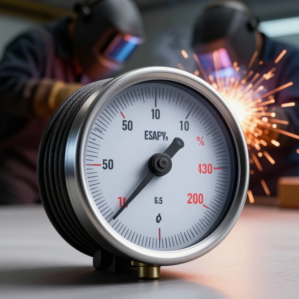
In my 18 years as a diagnostic specialist, I have found that many “ghost” issues in the shop—from tool chatter on a lathe to erratic weld beads—can be traced back to the power delivery system. We often focus on the mechanics of the tool while ignoring the lifeblood that feeds it. If your power cord cannot handle the amperage demand over its length, you are fighting a losing battle against physics.
Establishing Electrical Baselines for Heavy Fabrication
Electrical baselines are the known, measurable standards of power delivery that a machine requires to operate within its designed tolerances. Without a stable baseline, troubleshooting mechanical or metallurgical issues becomes impossible because the input variable is constantly shifting.
When we talk about power delivery in a metalworking context, we are primarily concerned with amperage capacity and voltage drop. Amperage is the volume of electricity flowing, while voltage is the pressure pushing it. If the “pipe” (the copper conductor) is too small for the “volume” (the amps), the “pressure” (the voltage) drops. This drop creates heat in the cord and malfunctions in the machine.
In a heavy fabrication environment, your equipment often demands between 100 and 300 amps. At these levels, even a small amount of resistance in an undersized cord becomes a major problem. Resistance generates heat, and heat increases resistance—a feedback loop that can eventually damage sensitive motor controllers or inverter boards.
- Amperage (Amps): The current flow required by your welder or motor.
- Voltage (Volts): The electrical potential; standard shop outlets are usually 220V-240V for heavy equipment.
- Voltage Drop: The loss of electrical pressure caused by the resistance of the wire over a specific distance.
- AWG (American Wire Gauge): The standard for measuring the diameter of the copper conductor; smaller numbers indicate thicker wires.
| Parameter | Ideal Range | Warning Sign | Critical Failure Point |
|---|---|---|---|
| Voltage Drop | < 3% | 5% – 7% | > 10% |
| Cord Temperature | Ambient + 10°F | Warm to touch | Hot/Smell of ozone |
| Resistance (Ohms) | < 0.2 per 50ft | 0.5 – 1.0 | > 2.0 |
| Arc Stability | Consistent hum | Intermittent crackle | Frequent arc outages |
Why Undersized Conductors Cause Welding Porosity and Arc Instability
Porosity in a weld is often blamed on shielding gas coverage, but electrical instability is a frequent and overlooked root cause. When a conductor is too thin for the amperage load, the arc voltage fluctuates, which directly affects the weld pool’s fluid dynamics and the gas shield’s integrity.
If you are running a 250-amp bead and your voltage drops because of a 10-gauge cord used over 50 feet, the inverter has to work twice as hard to maintain the arc. This creates “micro-stuttering.” You might not see it with the naked eye, but the arc is actually turning on and off or changing intensity rapidly. This turbulence in the arc plasma can pull atmospheric air into the weld pool, leading to nitrogen and oxygen entrapment—the very definition of porosity.
Furthermore, inconsistent power affects the wire feeder motor. If the motor doesn’t get a steady voltage, the wire feed speed (WFS) will vary. A sudden surge or dip in WFS changes the arc length, causing the “popcorn” sound and resulting in a bead that looks like a series of cold laps rather than a smooth, fused joint.
- Arc Blow: Erratic arc behavior often caused by magnetic fields or, in this case, unstable current flow.
- Duty Cycle Stress: Running a machine on an undersized cord forces the internals to run hotter, effectively lowering your machine’s rated duty cycle.
- Inverter Hunting: A condition where the machine’s electronics constantly try to compensate for falling voltage, leading to an audible “hunting” or surging sound.
Selecting the Right Copper Gauge for High-Amperage Workflows
Choosing the correct thickness for your power leads involves balancing the total amperage of the machine with the distance from the power source. This is a mathematical necessity, not a suggestion, to ensure the longevity of your equipment and the quality of your output.
In my experience, fabricators often underestimate the impact of distance. A cord that works perfectly at 10 feet may be dangerous at 50 feet. For a machine drawing 200 amps, you might move from a 4 AWG wire to a 2 AWG or even a 1/0 AWG as the distance increases. The goal is to keep the voltage drop under 3% at full load.
When you are troubleshooting a machine that keeps throwing “Low Voltage” error codes or a plasma cutter that won’t stay in the cut, the first thing I check is the AWG rating stamped on the cord jacket. If you are running 200 amps through a 12-gauge extension cord, you are lucky the cord hasn’t melted yet, let alone that the machine is struggling.
Copper Gauge Selection Guide (100–300 Amps)
| Amperage Load | 25 Feet | 50 Feet | 100 Feet |
|---|---|---|---|
| 100 Amps | 4 AWG | 2 AWG | 1/0 AWG |
| 150 Amps | 2 AWG | 1 AWG | 2/0 AWG |
| 200 Amps | 1 AWG | 1/0 AWG | 3/0 AWG |
| 250 Amps | 1/0 AWG | 2/0 AWG | 4/0 AWG |
| 300 Amps | 2/0 AWG | 3/0 AWG | 250 MCM |
Building on this data, it is important to remember that these ratings are for copper conductors. If you encounter aluminum wiring (rare in portable cords but common in shop headers), you must increase the thickness significantly to achieve the same conductivity.
Identifying Insulation Ratings for Industrial Shop Environments
The internal copper gauge is only half the battle; the outer jacket, or insulation, determines how long that cord will survive in a brutal shop environment. In a fabrication setting, cords are subjected to hot sparks, sharp metal offcuts, pools of coolant, and the occasional forklift tire.
I once saw a shop fire start because a standard “outdoor” cord had been used for a heavy-duty welder. The insulation wasn’t oil-resistant. Over six months, hydraulic fluid from a nearby press had softened the jacket until it turned into a gummy mess. Eventually, the hot slag from a grinder landed on it, melted straight through to the conductors, and caused a massive short.
For industrial metalworking, you should look for specific letter codes on the cord jacket. These codes tell you exactly what the insulation can handle.
- S: Service Grade (standard duty).
- O: Oil-resistant jacket.
- OO: Oil-resistant jacket and oil-resistant internal insulation.
- W: Weather and water-resistant (essential for damp shop floors).
- T: Thermoplastic.
- E: Elastomer.
For a heavy-duty fabrication environment, I always recommend SOOW or Type W cords. SOOW stands for Service, Oil-resistant jacket, Oil-resistant insulation, and Water/Weather resistant. Type W is even more robust, often used in mining and heavy industrial applications where the cord is literally dragged across abrasive concrete all day.
Systematic Troubleshooting of Power-Related Machine Errors
When a machine starts acting up, you need a systematic way to determine if the power cord is the culprit. We use a process of elimination, starting from the wall and moving toward the arc. Randomly changing settings on the welder is a waste of time if the input power is the bottleneck.
The most effective tool for this is a digital multimeter with a “Min/Max” function. This allows you to capture the lowest voltage reached during the split second the arc is struck. If the voltage sits at 240V while idling but drops to 205V the moment you pull the trigger, your cord is undersized or your connections are loose.
The Power Supply Diagnostic Checklist
- Visual Inspection: Check the cord jacket for nicks, burns, or soft spots. Feel the plugs after 10 minutes of use; they should be cool or only slightly warm.
- Voltage Drop Test: Measure the voltage at the outlet, then measure it at the machine’s input while under load. A drop of more than 7-10 volts on a 240V circuit is a red flag.
- Connection Integrity: Ensure the lugs inside the plugs are tight. Loose screws create high resistance, which leads to heat and voltage loss.
- Heat Tracking: Use an infrared thermometer to scan the length of the cord while the machine is running. “Hot spots” indicate internal strand breakage or a localized failure in the conductor.
- Ground Continuity: Check the resistance between the machine chassis and the shop’s main ground. It should be near zero Ohms. High resistance here can lead to high-frequency interference and “shocks” when touching the machine.
Why Tool Chatter and Vibrational Damage Link to Power Quality
It might seem strange to link the thickness of a power cord to the surface finish on a milled part, but the connection is real. In many shops, the same sub-panel feeds the welders and the manual or CNC machinery. If a welder is drawing heavy current through an undersized lead, it can cause “voltage sag” across the entire circuit.
When a lathe or mill motor experiences voltage sag, its torque output drops. To compensate, the motor’s slip increases, and the RPMs can fluctuate. This fluctuation disrupts the harmonic balance of the cut. Instead of a steady chip load, the tool begins to “bounce” or resonate, leading to tool chatter.
I worked with a machinist who was struggling with a 0.005-inch vibration on his spindle that only appeared in the afternoons. We spent days checking the bearings and the floor leveling. It turned out that the shop next door started their heavy welding shift at 2:00 PM. Their undersized power leads were pulling so much current that they were “dirtying” the power for the entire building, causing the machinist’s motor controllers to struggle with the inconsistent input.
- Resonant Harmonics: The natural frequency at which a machine vibrates; unstable power can trigger these frequencies by causing motor pulsing.
- Back-EMF: Electromotive force that works against the supply voltage; when supply is weak, back-EMF can cause motor overheating and erratic speeds.
- Spindle Backlash: While usually mechanical, erratic motor torque from poor power can make backlash issues appear much worse than they are.
Real-World Case Study: The Stuttering Wire Feeder
A client was experiencing intermittent wire feed issues on a high-end MIG setup. The wire would feed fine for 30 seconds, then stutter, causing the arc to burn back to the tip. They had replaced the drive rolls and the entire gun assembly.
I hooked up a recording multimeter to the primary power input. Every time the wire stuttered, I saw a 12-volt dip in the supply. We traced the power cord back to a junction box 80 feet away. The cord was a 10 AWG “heavy duty” extension they had bought from a big-box store. While 10 AWG is thick for a toaster, it was entirely insufficient for a 300-amp welder at that distance.
We replaced the 80-foot run with a custom-built 2 AWG SOOW lead. The stuttering vanished immediately. The machine’s internal computer was no longer struggling to keep the DC drive motor constant while the input voltage was bouncing around.
Lessons from the Field:
- Never trust the “Heavy Duty” label on a retail cord; check the actual AWG and insulation type.
- The longer the run, the thicker the copper must be.
- Heat is the ultimate diagnostic tool—if it’s hot, it’s wrong.
Actionable Tracking Framework for Shop Power Health
To prevent these issues from creeping back into your workflow, I recommend keeping a simple log of your equipment’s electrical health. This is just as important as oiling your ways or changing your filters.
- Baseline Log: Record the idle and load voltage for every major machine in your shop once a year.
- Cord Inspection Schedule: Every six months, inspect all primary power leads for jacket integrity and plug tightness.
- Labeling: Mark your heavy-duty cords with their AWG and maximum length. This prevents a worker from grabbing a “thin” cord for a “thick” job.
- Temperature Checks: During long production runs, use an IR temp gun to check the temperature of your power plugs. Anything over 120°F (49°C) warrants an investigation into the wire gauge or connection tightness.
By treating your power delivery as a precision component of your fabrication process, you eliminate a massive variable in your troubleshooting. When you know the power is solid, you can focus on the metallurgy, the gas flow, and the mechanical alignment with confidence.
Frequently Asked Questions
How do I know if my cord is too thin for my welder?
The most common signs are a warm or hot power cord, the machine throwing “low voltage” or “under-voltage” errors, and an unstable arc that sounds erratic. You can verify this by measuring the voltage at the machine while welding; if it drops more than 3-5% from the idle voltage, your conductor is likely too thin for that distance.
Can I just use two thinner cords in parallel to save money?
No. This is a dangerous practice that violates safety standards. Current does not always split evenly between two cords due to minor differences in resistance. This can lead to one cord carrying too much load, overheating, and causing a fire. Always use a single conductor of the correct gauge.
What does the “W” in SOOW stand for?
The “W” stands for weather and water resistance. This means the jacket is designed to withstand moisture and sunlight without cracking or degrading. In a shop environment, this is crucial if you ever have to work near open bay doors or on damp concrete floors.
Does the gauge of the ground clamp lead matter as much as the power cord?
Absolutely. The welding circuit is a loop. If you have a massive power cord but a thin, frayed ground lead, you still have high resistance in the circuit. This will cause the same arc instability and heat issues as an undersized power cord. Your ground lead should match the gauge of your electrode lead.
Why does my welder work fine for five minutes and then start acting up?
This is often due to heat-induced resistance. As an undersized cord carries current, it heats up. As copper gets hotter, its resistance increases. This creates a “snowball effect” where the voltage drop gets worse the longer you weld, eventually reaching a point where the machine can no longer compensate.
Is SOOW cord flexible enough for a portable welder?
Yes, SOOW and Type W cords use very fine strands of copper, making them extremely flexible even in cold temperatures. This is a major advantage over standard building wire (like THHN), which is stiff and can crack if moved frequently.
How much voltage drop is actually acceptable?
For industrial machinery, you should aim for less than 3% voltage drop. While many machines can technically run on a 5% or even 10% drop, you are sacrificing the life of the electronics and the quality of your welds. Staying under 3% ensures the machine operates exactly as the engineers intended.
Can I use a 50-foot 12-gauge cord for a 200-amp welder?
No. A 12-gauge cord is rated for about 20 amps in short distances. Attempting to pull 200 amps through it—even if the welder is only pulling that on the secondary side—will likely melt the cord or cause a fire. Even for the primary (input) side of a 200-amp welder, you typically need at least 8 or 6 AWG depending on the machine’s efficiency and distance.
Does the type of plug affect the cord choice?
The plug must be rated for the amperage the machine draws. If you have a 50-amp cord but use a 30-amp plug, the plug becomes the “fuse” in the system and will likely overheat and melt. Always match your plug, cord, and circuit breaker to the machine’s maximum input requirements.
What is the difference between AWG and MCM?
AWG (American Wire Gauge) is used for smaller diameters, up to 4/0. Once a wire gets thicker than 4/0, it is measured in MCM (thousands of circular mils). You will generally only see MCM ratings for very high-amperage industrial setups (300+ amps) or long-distance shop headers.
(This article was written by one of our staff writers, Paul Whitaker. Visit our Meet the Team page to learn more about the author and their expertise.)