Create a Simple Fabrication Inspection Checklist (Easy Fix)
I’ve spent 14 years in various shops, from cramped garage setups to heavy industrial floors. In that time, I’ve learned that the difference between a project that lasts decades and one that fails in a week usually comes down to what happens before the arc is even struck. I remember a specific project early in my career—a heavy-duty engine stand. I was confident in my welds, but I ignored a slight 1/8-inch gap in one of the primary load-bearing joints. Two days later, under the weight of a big-block V8, that joint buckled. It wasn’t the weld that failed; it was the fit-up. That near-miss taught me that structural integrity isn’t just about a pretty bead. It is about a disciplined approach to verifying every step of the process.

For many intermediate fabricators, the anxiety of a structural failure is real. You put hours of sweat and a significant amount of money into a project, only to worry if it will hold up under pressure. This guide is designed to help you build a reliable routine for reviewing your work. We will focus on manual checks, simple measurements, and physical principles that ensure your projects are safe, square, and strong. By using basic tools like calipers, squares, and straightedges, you can catch the subtle errors that lead to warping or cracking.
Analyzing Material Stress and Structural Integrity
Material stress refers to the internal forces within a metal component when an external load is applied. Understanding yield strength—the point where metal permanently deforms—is critical for selecting the right thickness and grade for your project to prevent sudden, catastrophic failure under weight or pressure.
When I design a frame, I start with the physics of the load. Every piece of metal has a “yield strength.” This is the amount of stress the material can handle before it stops acting like a spring and stays permanently bent. For common A36 structural steel, the yield strength is typically around 36,000 PSI. If your design pushes the metal close to this limit, you are in the danger zone. I always aim for a safety factor. For stationary projects, a 2:1 safety factor is common, meaning the structure is twice as strong as the maximum expected load. For anything overhead or moving, I push that to 4:1.
You also need to consider the load path. This is the route the weight takes from the point of impact down to the ground. If a load path is interrupted by a poorly placed joint or a thin piece of metal, that point becomes a “stress riser.” Stress risers concentrate force and lead to cracks. I use a straightedge to ensure my load-bearing members are perfectly aligned. Even a small offset can turn a compressive force (pushing) into a shear force (sliding), which metal handles much less effectively.
Metal Load and Stress Tolerances (Common DIY Materials)
| Material Type | Yield Strength (PSI) | Common Use Case | Safety Margin Suggestion |
|---|---|---|---|
| A36 Mild Steel | 36,000 | Frames, brackets, tables | 2:1 for static loads |
| 6061-T6 Aluminum | 35,000 | Lightweight carts, trim | 3:1 (due to fatigue) |
| 304 Stainless Steel | 30,000 | Food grade, outdoor decor | 2:1 |
| 4130 Chromoly | 63,000 | Roll cages, bike frames | 4:1 for impact safety |
- Tensile Strength: The maximum stress a material can withstand while being stretched or pulled before breaking.
- Shear Stress: Force tending to cause deformation of a material by slippage along a plane or planes parallel to the imposed stress.
- Brittle Fracture: A sudden break in a material with little to no plastic deformation, often caused by cold temperatures or internal defects.
Verifying Joint Preparation and Fit-Up Accuracy
Joint preparation involves cleaning, beveling, and aligning metal pieces before welding. Proper fit-up ensures that the weld bead can penetrate deeply into the base metal, creating a unified structure rather than a surface-level bond that might snap under moderate stress or vibration.
One of the biggest mistakes I see in home shops is “welding over dirt.” If your metal has mill scale, rust, or oil on it, your weld will be contaminated. I use a dedicated grinder with a flap disc to clean the metal until it shines like a mirror at least one inch back from the joint. This prevents porosity, which are tiny gas bubbles trapped in the weld that act like Swiss cheese, weakening the entire structure.
Fit-up is just as important as cleanliness. If you have a large gap between two pieces of metal, the weld has to bridge that distance. This creates a massive amount of internal stress as the molten metal cools and shrinks, often pulling the project out of square. I use feeler gauges or the shank of a drill bit to measure my root gaps. For most hobbyist projects using 1/8-inch to 1/4-inch material, a root gap of 1/16-inch is usually ideal. It allows the heat to reach the bottom of the joint for full penetration without making the hole too large to fill.
Critical Pre-Weld Verification Steps
- Check for Square: Use a machinist square on every corner. If it is off by even a degree, the error will multiply as the project grows.
- Verify Bevel Angles: For material thicker than 3/16-inch, grind a 45-degree bevel on the edges. This creates a “V” for the weld to sit in.
- Measure Root Opening: Ensure the gap is consistent across the entire joint using a set of calipers.
- Tack Weld Strategy: Place small tacks at the corners and midpoints. Re-measure for squareness after tacking, as the cooling metal will pull the joint.
Managing Heat-Affected Zones and Thermal Distortion
The heat-affected zone (HAZ) is the area of base metal that hasn’t melted but has had its properties changed by welding heat. Excessive heat leads to warping and internal stress, which can pull a project out of alignment or create brittle points prone to cracking.
Every time you weld, you are performing a mini-heat treatment on your metal. The area immediately surrounding the weld bead—the HAZ—gets hot enough to change its molecular structure but not hot enough to melt. In some metals, like high-carbon steel, this can make the area very brittle. I’ve seen trailers snap right next to a weld because the HAZ became too hard and couldn’t handle the vibration of the road.
To manage this, I focus on “heat input.” You want to get in, get the job done, and get out. Lingering too long with the torch pours unnecessary heat into the part. I also use a “back-stepping” or “staggering” technique. Instead of welding one long seam from left to right, I weld a few inches on one side, move to the opposite side of the project, and then come back. This balances the thermal expansion and keeps the structure from twisting into a pretzel.
- Thermal Expansion: The tendency of matter to change its shape, area, and volume in response to a change in temperature.
- Warping: A distortion where the surfaces of the metal become uneven or the overall shape twists.
- Residual Stress: Tension that remains in the metal after it has cooled down to room temperature.
Implementing a Visual Weld Inspection Routine
A visual inspection routine is a step-by-step look at completed welds to identify surface defects like porosity, undercut, or lack of fusion. By using simple tools like a magnifying glass and a weld gauge, you can catch errors that catch errors that compromise the strength of the joint.
Once the metal has cooled, I put on my “inspector hat.” I use a bright LED flashlight and a magnifying glass to look at the surface of the weld. I am looking for three main enemies: undercut, porosity, and overlap. Undercut looks like a small ditch dug into the base metal right at the edge of the weld. It effectively makes the metal thinner at that point, creating a perfect place for a crack to start.
Porosity looks like tiny pinholes. This usually means my welding gas flow rate was wrong or there was a breeze in the shop. For MIG welding indoors, I typically set my regulator between 15 and 20 CFH (Cubic Feet per Hour). If I see porosity, I grind the weld out completely and start over. There is no “fixing” porosity by welding over it; you just trap the weakness inside.
Common Weld Defects and Manual Solutions
| Defect | Visual Appearance | Likely Cause | Corrective Action |
|---|---|---|---|
| Undercut | A groove melted into the base metal. | Travel speed too fast or voltage too high. | Slow down and hold the edges of the joint longer. |
| Porosity | Small holes or “bubbles” on the surface. | Low gas flow or dirty metal. | Check regulator (15-20 CFH) and clean the joint. |
| Overlap | Weld metal sits on top without fusing. | Heat too low or travel speed too slow. | Increase voltage or amperage for better “wetting.” |
| Cracks | Thin lines in the center or edge. | Rapid cooling or brittle material. | Pre-heat thick sections and allow to cool slowly. |
Establishing Shop Safety and PPE Standards
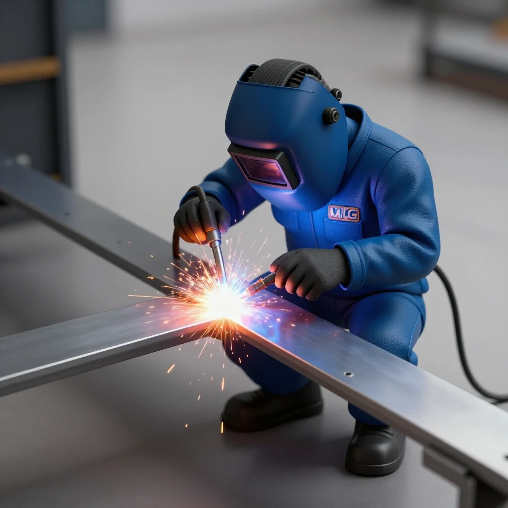
Workshop safety protocols are the habits and gear used to prevent injury from sparks, fumes, and intense light. This includes organizing the workspace to avoid trip hazards and ensuring that personal protective equipment (PPE) like welding helmets and respirators are in good working condition.
In my 14 years, I’ve seen more “close calls” from poor shop organization than from actual welding errors. A cluttered floor is a trip hazard when you are wearing a darkened welding helmet. I keep my garage fabrication safety zones clear of sawdust, cardboard, and flammable liquids. I also check my PPE every single morning. A scratched lens in a welding helmet isn’t just annoying; it causes eye fatigue that leads to poor weld quality.
For eye protection, I use an auto-darkening helmet set to the correct shade. If I’m welding thin sheet metal at low amps, Shade 10 is usually enough. For heavy plate at high amperage, I move up to Shade 12 or 13. I also never weld without a respirator designed for metal fumes. Even “clean” mild steel produces vapors that you shouldn’t be breathing. If you can see a “cloud” in your shop, your ventilation is insufficient.
PPE Shade and Safety Ratings
- Welding Helmet: ANSI Z87.1 rated with Shade 10-13 filters.
- Gloves: Top-grain leathers for MIG/TIG; heavy cowhide for Stick welding.
- Clothing: 100% cotton or leather. Synthetic fabrics like polyester can melt to your skin.
- Respirator: P100 rated filters to capture 99.9% of airborne metal particles.
- Fire Extinguisher: Class ABC, located within 10 feet of the welding area.
Why Weld Porosity Destroys Structural Integrity—And How to Spot It Before It Fails
Porosity is perhaps the most deceptive defect because it can hide just beneath a thin skin of metal. I call it “shop cancer.” If you see a single pinhole on the surface, there are likely dozens more inside the weld bead. This happens when the shielding gas—the invisible cloud that protects the molten metal from the air—is blown away or contaminated.
To spot this, I use a “pick test.” I take a sharp metal scribe and try to poke into any suspicious shadows on the weld. If the scribe sinks in, I know I have a void. Another trick is to look for “pepper” in the weld. If the bead looks dark and speckled rather than smooth and shiny, your gas coverage was weak. Checking your welding gas flow rate regularly is the easiest way to prevent this. If you are working near an open garage door, even a light 5 MPH breeze can strip your gas away, so I always use welding screens to block the wind.
How to Calculate Load Paths in Your Garage Projects
You don’t need a degree in engineering to understand basic load paths, but you do need to be observant. Think of water flowing through pipes. If the pipe gets smaller or has a sharp 90-degree turn, the pressure builds up. Force in a metal structure works the same way. When you design a project, ask yourself: “Where is the weight going?”
If you are building a workbench, the weight on the top should go directly into the vertical legs. If the legs are bolted to the side of the frame instead of sitting under it, the bolts are now carrying the entire load in “shear.” Bolts are strong, but they are not as strong as a solid steel column. I always try to design my joints so the metal is supporting the weight through direct contact, with the welds simply acting as the “glue” that keeps the pieces from sliding apart.
Structural Joint Review Checklist
- Direct Support: Does the load-bearing member sit directly on top of the support member?
- Weld Length: Is there enough “linear inches” of weld to hold the weight? (A general rule is that 1 inch of a 1/4-inch fillet weld can hold roughly 12,000 lbs in a static load).
- Symmetry: Is the load centered? Off-center loads cause “eccentric loading,” which tries to twist the beams.
- Triangulation: Are there diagonal braces to prevent the structure from “racking” or leaning to one side?
Maintaining Gas Flow Calibration for Cleaner Welds
I’ve found that many intermediate fabricators set their gas regulator once and never look at it again. This is a mistake. Over time, the ball in the flowmeter can get stuck, or small leaks can develop in the gas line. I perform a “purge test” at the start of every session. I hold the torch near my ear (with the wire feeder disengaged) and pull the trigger to hear the “hiss” of the gas.
If the flow is too low (under 10 CFH), you get porosity. If it is too high (over 30 CFH), you can actually create turbulence that pulls outside air into the weld pool, causing the very problem you are trying to avoid. Staying in that 15–20 CFH sweet spot is the “Goldilocks zone” for most shop environments. I also use a nozzle gel to prevent “spatter” from building up inside the torch shroud, which can block the gas flow and cause uneven coverage.
Diagnostic Inspection Framework for Completed Projects
After the welding is done and the safety gear is put away, I perform a final walkthrough. This is my “quality gate” before the project is painted or put into service. I use a numbered system to ensure I don’t miss anything.
- Dimensional Check: Use a tape measure to check the length, width, and height against your original plan. If one side is 1/4-inch longer than the other, the structure is under internal tension.
- Squareness and Twist: Place the project on a known flat surface (like a cast-iron table). If it wobbles, it has “twist.” This is caused by uneven heating during welding.
- Visual Bead Review: Look at every inch of weld. Use a “fillet gauge” to ensure the weld is the correct size. If you are welding 1/4-inch plate, your weld bead should also be roughly 1/4-inch wide.
- The “Ring” Test: For heavy structural frames, I sometimes give the metal a light tap with a hammer. A solid structure will have a clear, high-pitched “ring.” A dull “thud” can sometimes indicate a major internal crack or a loose joint, though this is more of an old-school shop trick than a scientific test.
- Cleanliness: Remove all slag and spatter. Spatter isn’t just ugly; it can hide small cracks and provides a place for rust to start.
Practical Next Steps for Your Next Project
Building a reliable structure is about small, repeatable wins. On your next project, don’t just start cutting and welding. Spend the first 20 minutes setting up your “review station.” Lay out your square, your calipers, and your flashlight. Make a commitment to check for square after every four tack welds.
By slowing down and verifying the physical reality of your project at every stage, you remove the guesswork. You transition from “hoping it holds” to “knowing it will.” Start small—maybe a simple tool rack or a welding cart—and practice these inspection steps. Over time, they will become second nature, and the quality of your work will reflect that discipline.
FAQ: Common Questions About Manual Fabrication Review
How do I know if my weld has “deep enough” penetration?
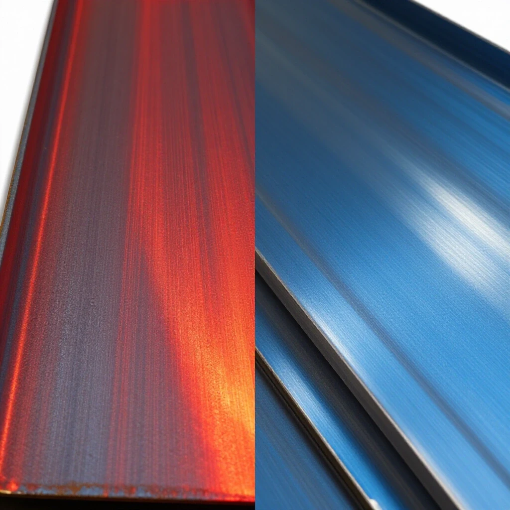
Without cutting the metal in half, you can look for “heat tint” on the back side of the joint. If you are welding 1/8-inch steel and you see a slight discoloration or a small bump of metal on the reverse side, you have achieved full penetration. If the back side looks brand new, your weld is likely just sitting on the surface.
What is the easiest way to fix a warped frame?
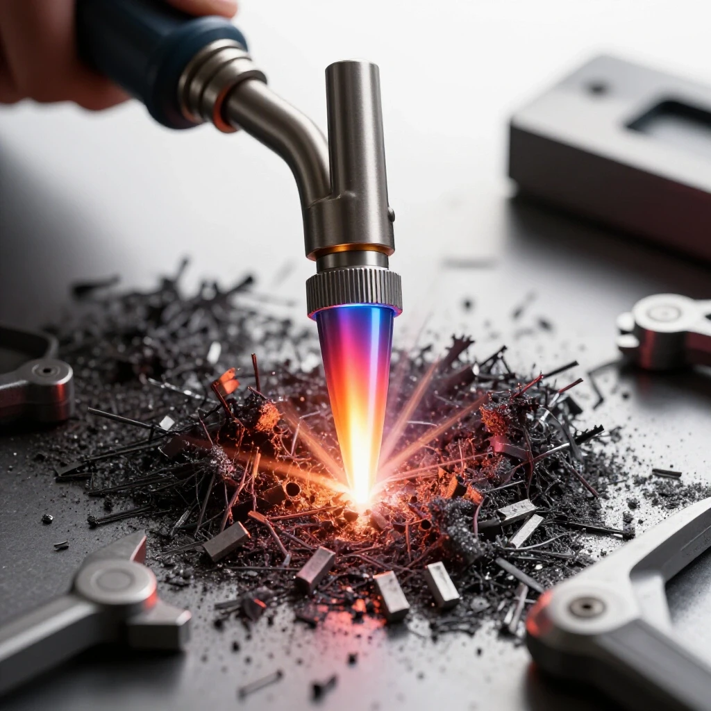
The best “fix” is prevention through staggered welding. However, if a frame is already warped, you can sometimes use “flame straightening.” This involves heating the side opposite the warp and letting it cool. As it shrinks, it pulls the metal back. This is a delicate process and should be practiced on scrap first.
Can I trust a weld that has a small amount of undercut?
It depends on the load. For a non-structural project like a shelf bracket, a tiny bit of undercut is mostly a cosmetic issue. For anything structural, like a trailer hitch or an engine hoist, any undercut is a failure point. Grind it down and add another small pass to fill the groove.
Why does my welder keep “popping” and leaving brown soot?
This is usually a sign of poor gas coverage or a “long arc.” If you hold the torch too far away, the shielding gas disperses before it hits the metal. Keep your “stick-out” (the distance from the tip to the metal) around 3/8-inch. The brown soot is oxidized metal, which indicates the weld was exposed to air.
How often should I check my squareness during a build?
Check it more often than you think you need to. I check before tacking, after tacking, and after every major weld bead. Metal moves significantly as it heats and cools. If you catch a movement early, you can usually tap it back into place with a dead-blow hammer.
Is mill scale really that big of a deal?
Yes. Mill scale is a layer of oxidized iron created during the hot-rolling process. It has a higher melting point than the steel beneath it. If you weld over it, the arc has to fight through the scale, often leading to a “cold” weld that doesn’t actually fuse with the base metal.
What tools are essential for a basic quality review?
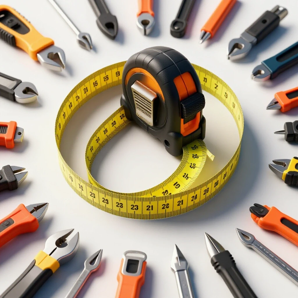
You don’t need fancy electronics. A high-quality 12-inch combination square, a set of 6-inch dial or digital calipers, a bright LED flashlight, and a straightedge (like a level or a piece of cold-drawn flat bar) are enough to catch 90% of fabrication errors.
How do I determine the right weld size for my material?
A good rule of thumb is that the “leg” of the weld (the distance from the corner to the edge of the bead) should be equal to the thickness of the thinnest piece of metal you are joining. If you are joining 1/4-inch plate to 1/2-inch plate, a 1/4-inch weld is your target.
What does “lack of fusion” look like?
Lack of fusion often looks like a “cold” weld where the edges of the bead look like they are just sitting on top of the metal rather than blending in. If the edge of the weld bead is rounded like a bead of water on a waxed car, it hasn’t fused properly. It should “wet out” and look flat or slightly concave at the edges.
Should I use a safety factor of 2:1 or 4:1?
If a failure results in a broken tool, 2:1 is fine. If a failure results in an injury, go with 4:1. When in doubt, more metal is cheaper than an accident. However, remember that adding more metal also adds more weight and more heat-distortion potential, so focus on smart design over just “making it thicker.”
(This article was written by one of our staff writers, James Harlan. Visit our Meet the Team page to learn more about the author and their expertise.)