Essential Clamping Setups for Strong Welding Jigs (Guide)
I remember standing over a ten-foot steel gate early in my career, staring at a gap that shouldn’t have been there. I had measured every piece of square tubing twice and cut them to the exact millimeter. However, as soon as I finished the final corner, the entire frame had pulled into a trapezoid. It was a humbling lesson in the physical forces of thermal expansion. No matter how accurate your cuts are, the moment you introduce heat, the metal wants to move. Without a rigid system to counteract those forces, your project is at the mercy of physics.
In my fourteen years on the shop floor and as a mechanical inspector, I have seen that the difference between a professional-grade build and a scrap-pile mistake often comes down to how you secure your work. We are dealing with massive amounts of internal stress. When metal is heated, it expands; as it cools, it contracts with enough force to bend thick steel plates. If you are not using a robust method to hold your components in place, you are essentially guessing at the final dimensions. This guide focuses on the mechanical principles of workholding to ensure your projects remain square, true, and structurally sound.
Understanding Mechanical Resistance in Fabrication Fixtures
Mechanical resistance refers to the ability of a clamping system to counteract the internal stresses generated during the heating and cooling of metal workpieces. By applying external pressure, a fabricator can prevent the metal from warping or pulling out of its intended alignment. This process ensures that the finished structure meets the required dimensional tolerances and maintains its intended load capacity.
When you secure a joint, you are fighting a battle against the metal’s yield strength. As the joint cools, the shrinking metal pulls on the surrounding material. If your clamps are weak or poorly placed, the metal will reach its yield point and permanently deform. I always recommend a safety factor of at least 2:1 when calculating the number of clamps needed. If you think two clamps will hold a joint, use four.
In my experience, the most common failure in home shops is underestimating these forces. I once saw a heavy H-beam frame twist a 1-inch thick steel table because the fabricator didn’t account for the cumulative pull of several large joints. We use fixtures not just to hold things together, but to force the metal to stay put while it undergoes these massive internal changes. This is why understanding the “3-2-1 principle” of location is vital. You need three points to define a plane, two to define a line, and one to define a point. If your jig follows this rule, your parts will land in the same spot every single time.
Critical Components for Secure Workholding Systems
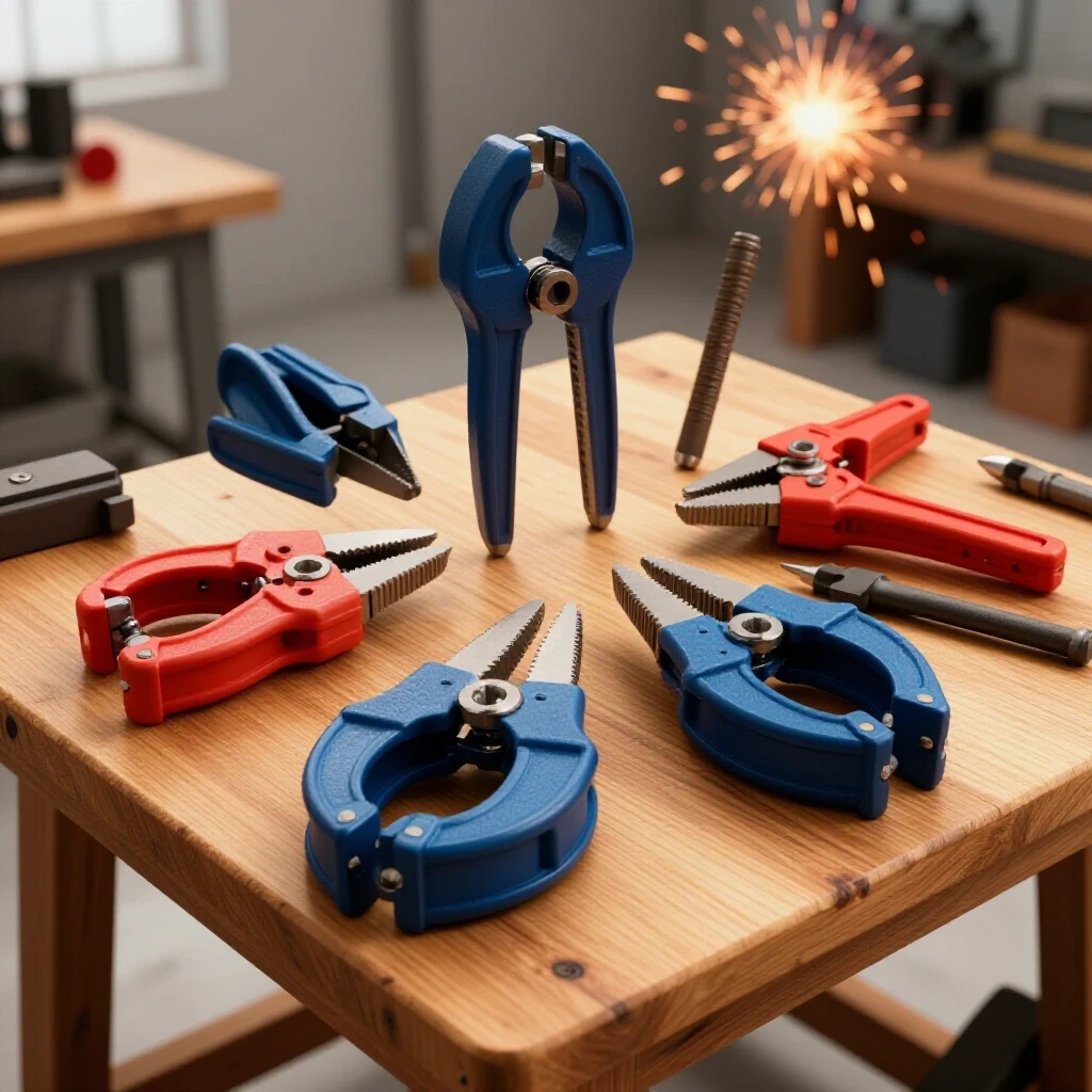
A secure workholding system relies on several key tools designed to provide repeatable pressure and precise alignment. These include manual C-clamps, fast-acting toggle clamps, heavy-duty angle plates, and fixed stops that act as a reference for the workpiece. Each tool serves a specific purpose in resisting movement and ensuring that the assembly remains square throughout the entire fabrication process.
Selecting the right tool for the job is the first step in preventing fabrication errors. For heavy structural work, I rely on the classic C-clamp. It provides the highest amount of closing force, which is necessary when you are trying to flatten a slightly bowed piece of plate. However, for repetitive tasks, toggle clamps are superior because they offer consistent pressure and can be engaged with a single motion.
| Tool Type | Primary Use | Closing Force | Best For |
|---|---|---|---|
| C-Clamp | Heavy structural joints | High (Up to 2,000+ lbs) | Thick plate and beams |
| F-Clamp (Sliding) | General assembly | Medium | Long reaches and quick setups |
| Toggle Clamp | Repetitive production | Low to Medium | Light gauge tubing and sheet |
| Angle Plate | 90-degree alignment | N/A (Rigid Support) | Squaring vertical members |
| Locking Pliers | Temporary tacking | Low | Small parts and thin material |
Interestingly, many people forget about the importance of “stops.” A stop is simply a block of metal bolted or welded to your table that prevents a part from sliding. If you combine a strong stop with a toggle clamp, you create a “locating nest.” This setup ensures that even if you get bumped or the metal pulls hard, the part has nowhere to go. In industrial settings, we use hardened steel stops to ensure that even after a thousand uses, the jig remains accurate to within a few thousandths of an inch.
The Physics of Thermal Expansion and Workpiece Constraint
Thermal expansion is the tendency of matter to change its shape, area, and volume in response to a change in temperature. In metalworking, this expansion creates significant internal pressure that can lead to structural warping if the workpiece is not properly constrained. Controlling this movement through strategic clamping allows the fabricator to manage where the stress is distributed within the metal.
Every metal has a specific coefficient of thermal expansion. For example, stainless steel expands significantly more than carbon steel. If you are building a frame out of 304 stainless, you must be twice as diligent with your clamping as you would be with mild steel. I have seen stainless frames pull themselves apart because the fabricator didn’t allow the heat to dissipate before releasing the clamps.
To manage this, you must understand the “neutral axis” of your parts. This is the area of a beam or tube that experience the least amount of stress during bending. When you clamp a joint, you want to apply pressure in a way that supports this axis. If you only clamp the edges, the center of the material can still bow. This is often called “oil-canning” in sheet metal, but it happens in heavy plate too.
- Always clamp as close to the joint as possible without obstructing your workspace.
- Use heat sinks, such as thick copper or aluminum blocks, under your clamps to help pull heat away from the joint.
- Balance your clamping pressure. If you clamp one side of a long beam and not the other, the beam will bow toward the unclamped side.
- Wait for the metal to reach room temperature before removing the clamps. If the metal is still “hand-hot,” it still has enough energy to move.
Safety Protocols for High-Pressure Clamping Environments
Safety in a fabrication environment involves more than just eye protection; it requires an understanding of the stored energy within tightened clamps and heavy fixtures. High-pressure clamping can lead to tool failure or the sudden release of parts if the equipment is damaged or used beyond its load capacity. Maintaining a clean workspace and inspecting tools for fatigue are essential steps in preventing workshop accidents.
I have witnessed a C-clamp “ping” across a room because the threads were stripped and the pressure was too high. It sounds like a gunshot, and the flying metal can be lethal. This is why a workshop safety checklist is non-negotiable. Before you start any project, you should inspect your clamps for bent screws, cracked frames, or worn pads. If a clamp doesn’t turn smoothly by hand, don’t use a wrench to force it; that’s a sign that the tool is failing.
- Check for Tool Fatigue: Look for hairline cracks in the “throat” of your C-clamps.
- Clear the Swing Zone: Ensure that if a clamp slips, it won’t hit you or a gas hose.
- Secure the Table: Make sure your welding table is anchored or heavy enough that the clamping force won’t tip it over.
- Avoid Over-Tightening: You are looking for a firm hold, not trying to crush the metal. Over-tightening can lead to “brittle fracture” in the clamp itself.
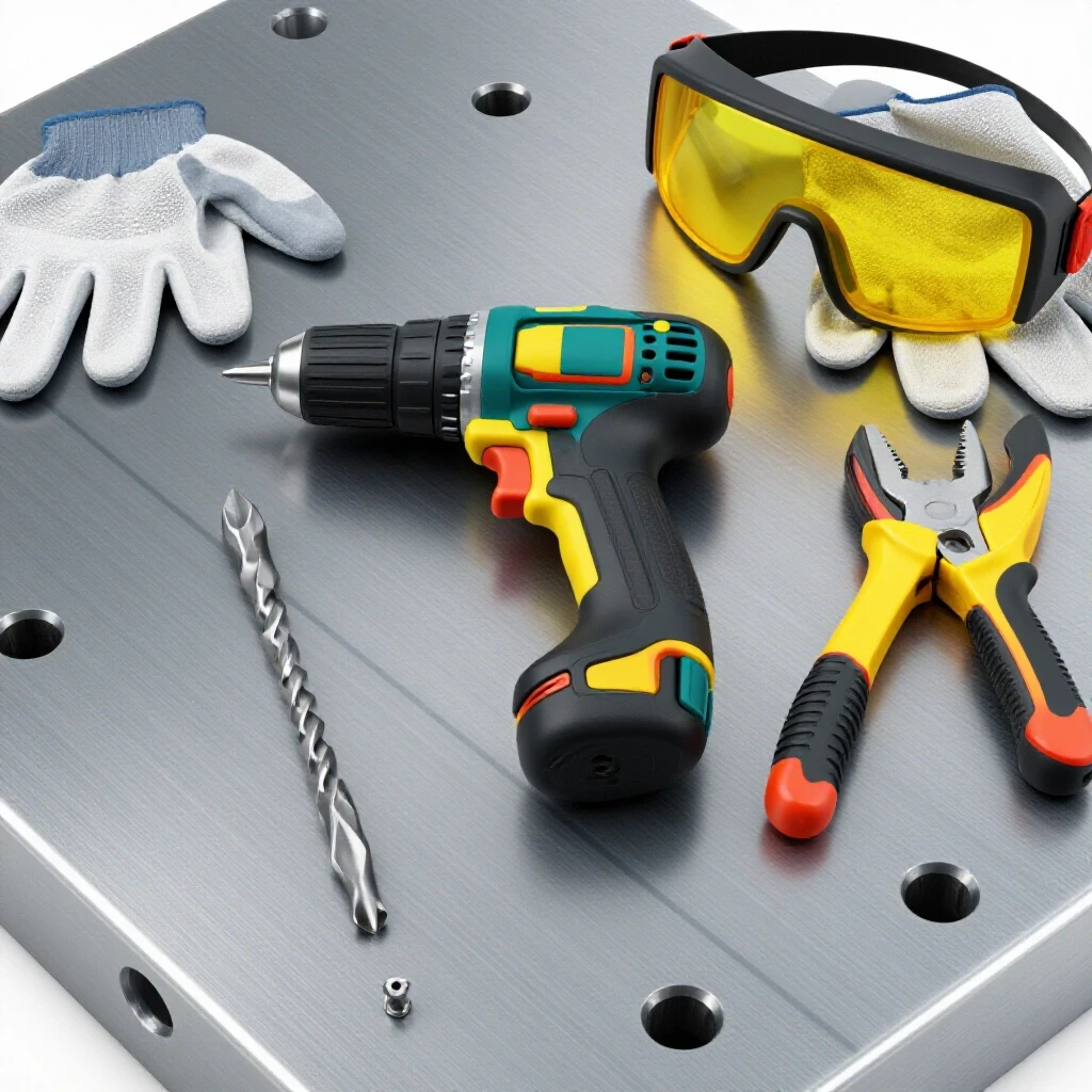
- Use Proper PPE: Wear gloves to prevent pinches and safety glasses to protect against flying debris if a tool fails.
In my shop, I follow a strict “no-cheater-pipe” rule. If you need a pipe to get enough leverage on a clamp, you are using the wrong tool or the wrong setup. You should be able to achieve the necessary hold using only your hand strength and the mechanical advantage built into the tool.
Step-by-Step Jig Construction for Structural Alignment
Constructing a jig involves building a temporary or permanent frame that holds all components of a project in their exact locations. This process begins with a flat, stable base and uses various locators to ensure that every piece of the assembly is perfectly aligned before any joining begins. A well-built jig reduces the risk of structural failure and ensures that multiple parts can be made with identical dimensions.
Building a jig is like building a foundation for a house. If the foundation is crooked, the whole house will be crooked. I start by verifying the flatness of my table using a machinist’s straight edge. If the table has a dip, I use shims to level my jig base. This is where many intermediate fabricators fail; they assume their table is flat when it might have a 1/8-inch bow from years of heat.
- Step 1: Define Your Base. Use a heavy piece of plate or a dedicated welding table with a grid of holes.
- Step 2: Set Your Primary Locators. These are your “stops” that define the outer dimensions of your part.
- Step 3: Add Vertical Support. Use angle plates to ensure that vertical members are at exactly 90 degrees.
- Step 4: Apply Clamping Pressure. Use F-clamps or toggle clamps to push the workpieces firmly against the stops.
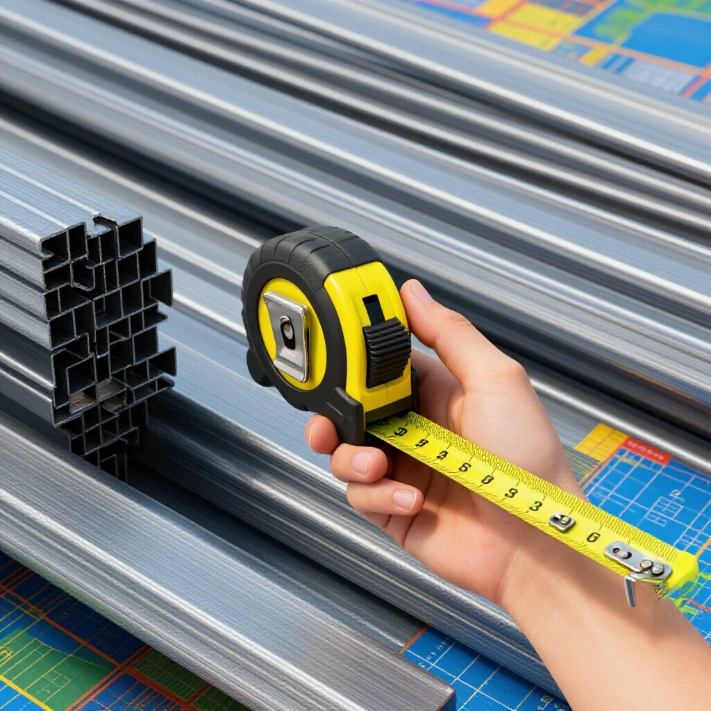
- Step 5: Verify Dimensions. Use a square and a tape measure to check the assembly one last time before proceeding.
I once worked on a project where we had to build 50 identical brackets for a heavy equipment trailer. By spending four hours building a precise jig with toggle clamps and hardened stops, we were able to finish the entire run in a single afternoon. More importantly, every single bracket was identical to within 0.5 millimeters. Without that jig, each one would have required manual layout and clamping, leading to inevitable errors and wasted material.
Troubleshooting Common Alignment Failures
Alignment failures occur when a finished fabrication does not meet the specified dimensions or is no longer square after being removed from the jig. These issues are typically caused by insufficient clamping force, incorrect placement of locators, or failing to account for the metal’s natural tendency to pull toward the center of a joint. Identifying these issues early allows for corrective action before the project is completed.
If you find that your project is warping despite your best efforts, the first thing to check is your “clamping sequence.” The order in which you secure and work on your parts matters immensely. If you clamp the entire project and then work from one end to the other, the heat will build up and cause a “sweeping” bend. Instead, I recommend working from the center out or using a “staggered” approach to distribute the heat evenly.
| Problem | Likely Cause | Corrective Action |
|---|---|---|
| Angular Distortion | Heat pulling the joint inward | Use a “draw” clamp to pull the joint slightly past 90 degrees before starting |
| Bowing (Long Members) | Unbalanced heat on one side | Clamp a “back-to-back” stiffener to the member during the process |
| Twisting | Uneven table surface or loose jig | Re-verify table flatness and tighten all jig locators |
| Dimensional Shrinkage | Natural contraction of the metal | Add a “shrinkage allowance” (usually 1/32″) to your initial layout |
Another common mistake is what I call “over-clamping.” If you hold a piece of metal so tightly that it cannot move at all, the internal stresses have nowhere to go. This can lead to “cracking” in the joint because the metal wants to shrink but the clamps won’t let it. The goal is to hold the part in alignment while allowing it to absorb the stress internally. This is a delicate balance that comes with experience, but a good rule of thumb is to ensure your clamps are firm but not “crushing” the material.
Actionable Tracking: Pre-Fabrication Checklist
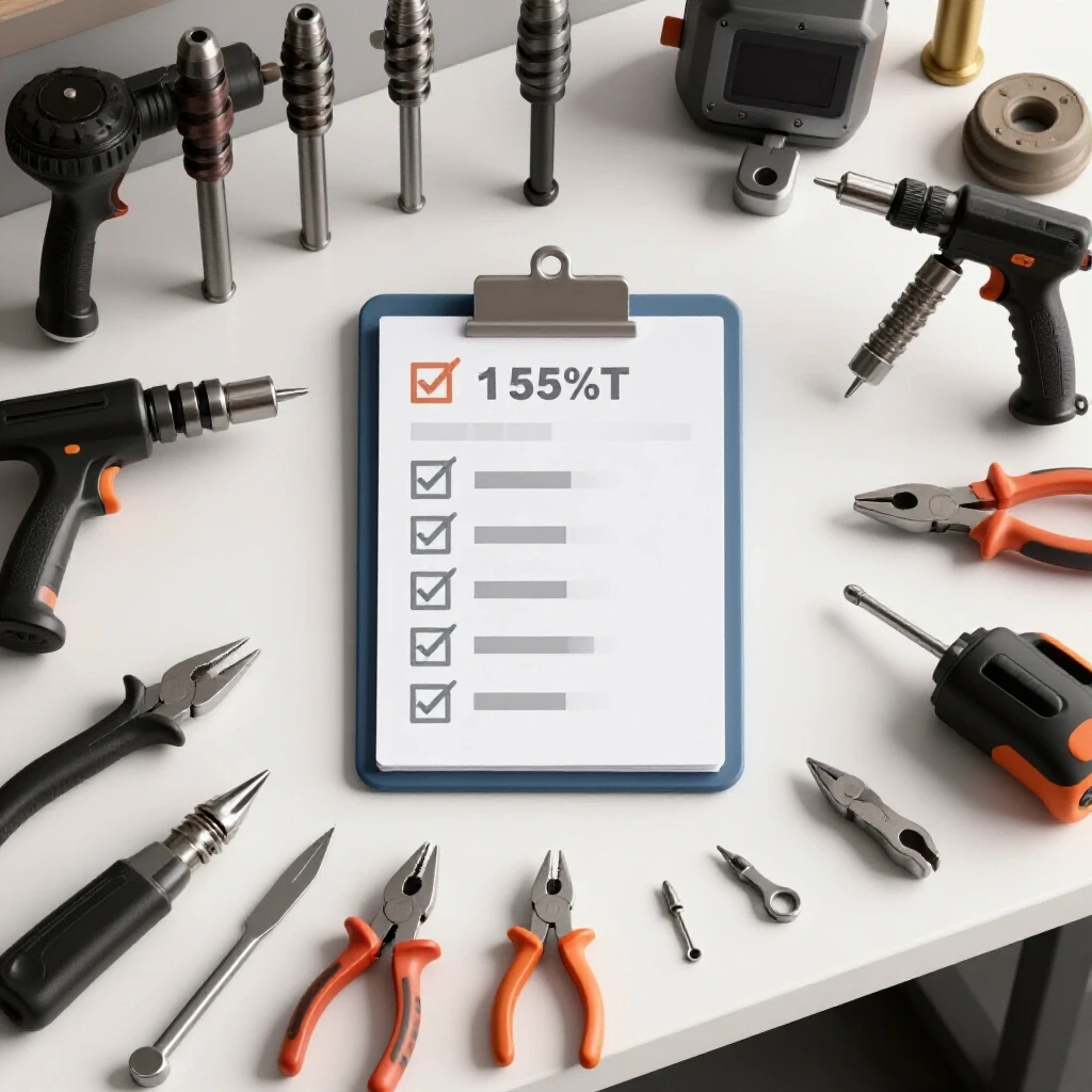
To ensure a successful build, I use a checklist for every major assembly. This keeps me from rushing and ensures that I haven’t missed a critical safety or alignment step.
- Table Flatness Check: Is the work surface true to within 1/16″ over 4 feet?
- Tool Inspection: Are all C-clamps free of rust and damaged threads?
- Stop Verification: Are all fixed stops securely bolted or tacked to the table?
- Material Prep: Are all contact points for the clamps clean and free of mill scale?
- Safety Zone: Is the floor clear of trip hazards and are fire extinguishers accessible?
- Sequence Plan: Have I determined the order of operations to minimize heat buildup?
- Cooling Time: Is there a designated area for parts to sit while they return to room temperature?
By following these steps, you move from “hoping” your project stays straight to “knowing” it will. In the world of structural fabrication, data and preparation are your best friends. We aren’t just sticking metal together; we are managing forces that are stronger than we are. Respect those forces, use the right tools, and your work will reflect the quality and safety that defines a true craftsman.
Frequently Asked Questions
How much clamping force is actually needed for a standard 2-inch square tube frame?
For 1/8-inch wall square tubing, you don’t need thousands of pounds of pressure. A standard F-clamp or a heavy-duty toggle clamp providing 300 to 500 pounds of force is usually sufficient to hold the part against a stop. The key is not the total pressure, but the rigidity of the stop it is being pushed against.
Can I use wood blocks as spacers in my metalworking jigs?
I strongly advise against using wood in any jig. Wood is compressible and can catch fire or char, which changes its dimensions. Even a slight compression in a wood block will allow the metal to move as it heats up. Always use steel, aluminum, or copper spacers to ensure a non-compressible, fire-resistant setup.
What is the best way to prevent a long flat bar from bowing when I work on one side?
This is a classic problem called “longitudinal bowing.” The best solution is to clamp the bar to a “strongback”—a much thicker piece of steel—during the process. Alternatively, you can clamp two identical bars back-to-back and work on them simultaneously. This allows the pulling forces of each bar to cancel the other out.
Why do my parts still move after I take them out of the jig, even if I waited for them to cool?
This is usually due to “residual stress.” Even if the part is cool, the internal forces from the process are still there. If your jig was holding the part in a forced position that it didn’t want to be in, it will “spring back” once released. To prevent this, ensure your parts fit perfectly in the jig without being forced before you start.
How do I know if a toggle clamp is strong enough for my application?
Toggle clamps are rated by their “holding capacity.” For most light to medium fabrication, a clamp rated for 500 to 750 lbs is a safe bet. However, remember that this rating is the force required to break the clamp, not necessarily the force it applies. Always look for the “exerted force” specification in the tool’s data sheet.
Should I tack weld my parts while they are in the jig or fully join them?
I always recommend doing all your tacking while the part is fully clamped in the jig. Once the tacks are set and have cooled slightly, you can often remove the part from the jig to finish the work, provided you follow a balanced sequence. However, for high-precision frames, I leave the parts in the jig for the entire process.
Is it necessary to use copper pads on my clamps?
Copper pads are excellent for two reasons: they prevent the hardened steel of the clamp from marring your workpiece, and they act as a heat sink. While not strictly “necessary” for structural integrity, they are a hallmark of a high-quality shop and help maintain the surface finish of your material.
How can I check if my jig is square if I don’t have an expensive granite table?
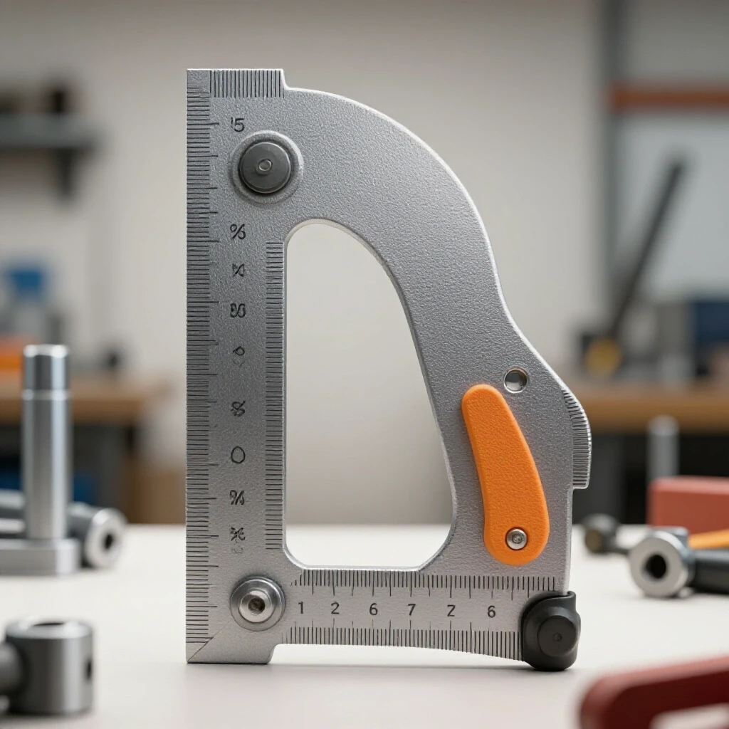
You can use the “3-4-5 rule” for larger frames. Measure 3 feet on one side, 4 feet on the other, and the diagonal should be exactly 5 feet. For smaller jigs, a high-quality machinist’s square is essential. Always check your square against a known 90-degree reference before trusting it for a major project.
(This article was written by one of our staff writers, James Harlan. Visit our Meet the Team page to learn more about the author and their expertise.)