How to Check and Verify Joint Fit-Up Angles Safely (Tips)
I have spent 14 years in the world of metal fabrication, moving between the precision of mechanical engineering and the grit of the shop floor. Early in my career, I assumed that if a part looked square, it was close enough for the arc to fix the rest. I was wrong. A single degree of error in a pre-weld assembly can translate into inches of misalignment across a large frame. More importantly, forcing parts to fit when the geometry is off introduces internal stresses that can lead to structural failure long after the project leaves your bench.
In my time inspecting heavy industrial frames, I have seen how a lack of rigor during the initial layout leads to “near-miss” accidents. I once watched a 500-pound assembly slip from a fixture because the technician had not verified the mating surface angles before clamping. The resulting imbalance caused a support to buckle. This guide is about preventing those moments. We will focus on the technical discipline of verifying your workpieces are positioned correctly and safely before you ever pick up a torch.
The Physical Impact of Geometric Precision in Pre-Weld Staging
Pre-weld staging is the process of arranging, measuring, and securing metal components to ensure they align with your design before the joining process begins. It is the most critical phase for ensuring the final structure behaves as intended under load.
When you verify the orientation of your workpieces, you are managing how energy will move through the finished part. If a joint is supposed to be at 90 degrees but sits at 92, the load path changes. This can create unintended shear stress, where forces push parts in opposite directions, rather than the compressive or tensile forces the design expects. By confirming your geometry early, you protect the structural metal load capacity of the final build.
Furthermore, proper alignment limits the size of the heat-affected zone (HAZ). The HAZ is the area of base metal that does not melt but has its microstructure changed by the heat of welding. If your fit-up is poor and leaves a large, uneven gap, you will need more heat and filler metal to bridge it. This excess heat expands the HAZ, which is often where structural cracking begins. A tight, verified fit-up keeps the heat concentrated and the metal strong.
Essential Manual Tools for Confirming Joint Alignment
Manual instrumentation refers to the handheld mechanical and digital tools used to measure degrees, perpendicularity, and parallelism between mating surfaces. These are the primary defenses against fabrication errors in a home or small-scale shop.
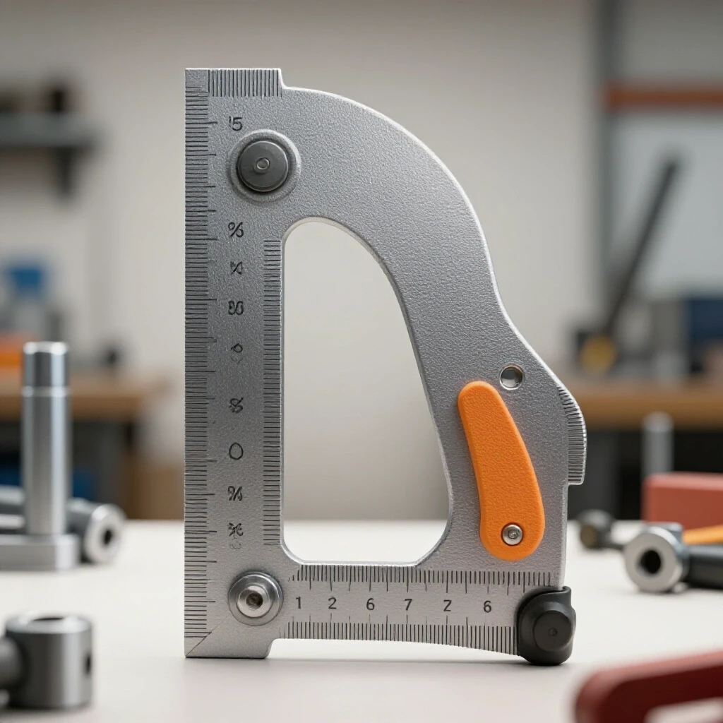
I rely on a few core tools that have proven their worth over a decade of inspections. The combination square is the workhorse. It allows you to check for a 90-degree “square” relationship and a 45-degree miter. However, even a high-quality square can be knocked out of alignment if dropped. I always check my squares against a known “master” block or by using the geometric 3-4-5 rule on a flat table before starting a project.
Digital angle finders have become more common in the last few years. These tools use electronic sensors to provide a readout, often to a tenth of a degree. While they are incredibly helpful for non-standard bevels, they require a perfectly flat reference surface to be accurate. If your welding table is bowed, your digital reading will be false. Always use a precision straightedge to verify your work surface is flat before trusting an electronic gauge.
| Tool Type | Best Use Case | Precision Level | Safety Consideration |
|---|---|---|---|
| Combination Square | 90-degree butt joints | High (Mechanical) | Watch for sharp edges on the stainless steel blade |
| Digital Angle Finder | Non-standard bevels/slopes | Very High (Electronic) | Requires a calibrated, flat reference surface |
| Sliding T-Bevel | Transferring unique angles | Moderate | Ensure the locking nut is tightened firmly |
| Machinist Protractor | Fine-scale degree checks | High | Small parts can be hard to handle with gloves |
| Magnetic Squares | Holding light parts in place | Low (for check only) | Do not rely on magnets for structural stability |
Establishing a Secure Staging Environment for Layout
A secure staging environment is a workspace organized to prevent material movement and operator injury during the measurement and alignment phase. Safety in the shop starts long before the sparks fly.
Garage fabrication safety often fails at the workbench. If you are trying to verify the angle of a heavy piece of tubing while balancing it on a stack of scrap wood, you are inviting a crush injury. I have seen heavy steel sections slide off makeshift supports, pinning a fabricator’s hand or foot. Every piece of material should be supported by a stable, level surface that can handle the weight without flexing.
Clamping is not just for holding parts during welding; it is a vital part of the verification process. I use F-style clamps or C-clamps to “freeze” the joint once I believe the angle is correct. This allows me to step back, re-measure with a square, and ensure nothing shifted when I tightened the grip. Always place your hands away from potential pinch points—the areas where the clamp meets the metal—and wear leather work gloves to protect against burrs and sharp edges.
Safety Risks and PPE During the Layout Phase
The layout phase involves handling raw metal, which carries specific risks like lacerations, eye injuries from metal slivers, and ergonomic strain. Even if you aren’t welding yet, your personal protective equipment (PPE) is mandatory.
Many fabricators skip eye protection during the measurement phase, but this is a mistake. When you slide a steel square along a freshly cut edge, tiny metal burrs can flake off. I always wear Z87+ rated safety glasses from the moment I enter the shop. Additionally, if you are performing small tack welds to hold your verified angles, you must use a welding helmet with the correct filter. For most garage projects, a Shade 10-13 filter is the standard for protecting your retinas from “arc flash.”
Workshop safety also involves managing your environment. Ensure your welding gas flow rate is set correctly (typically 15–20 CFH for MIG) and that your ventilation is active if you plan to tack-weld your verified joints. Breathing in fumes from galvanized coatings or mill scale is a health hazard that can be avoided with a simple respirator or a high-volume exhaust fan.
- Hand Protection: Use cowhide or goatskin gloves to handle material.
- Eye Protection: Clear Z87+ glasses for layout; Shade 10-13 for tacking.
- Footwear: Steel-toed or composite-toed boots to prevent crush injuries from falling stock.
- Hearing Protection: Use earplugs if you are using grinders to clean joint faces before fit-up.
Step-by-Step Procedure for Verifying Geometry
To ensure a project remains stable and accurate, I follow a specific sequence of checks. This prevents “stacking errors,” where a small mistake at the beginning of a build grows into a major problem by the end.
- Clean and Deburr: Use a file or a flap disc on a grinder to remove all burrs from the cut edges. A tiny piece of metal stuck in the joint will throw your angle off by several degrees.
- Establish a Baseline: Place your primary piece on the table and clamp it down. This is your “datum” or reference point.
- Initial Placement: Bring the second piece into contact. Use your combination square to get it into the approximate position.
- Check for Gaps: Look for “daylight” between your square and the metal. If you see light, the joint is not flush. Adjust the cut or the position until the square sits perfectly against both surfaces.
- Secure and Re-Verify: Apply a clamp to hold the parts. Tightening a clamp often pulls the metal slightly. Once the clamp is tight, check the angle one last time.
- Measure Diagonals: If you are building a rectangular frame, measure from corner to corner. If the two diagonal measurements are identical, your frame is square.
Interestingly, temperature can affect these measurements. If one piece of metal has been sitting in the sun and the other in a cold shop, they may have expanded at different rates. I try to let all materials reach shop temperature before performing my final verification.
Common Geometric Discrepancies and Their Root Causes
A discrepancy is any deviation from the intended design angle or alignment. Understanding why these happen allows you to fix the root cause rather than just fighting the symptom.
One frequent issue is “saw wander.” If your cold saw or abrasive chop saw blade is dull or pushed too hard, it can flex. This creates a cut that is not perfectly vertical. When you try to join two of these pieces, they will never sit at a true 90-degree angle because the faces are beveled. I always check the squareness of the cut itself before I try to fit the joint together.
Another cause of poor fit-up is improper mill scale removal. Mill scale is the dark, flaky layer of iron oxide found on hot-rolled steel. It is brittle and uneven. If you measure your angles on top of heavy scale, your square might be resting on a high point, giving you a false reading. Grinding the contact areas down to “bright metal” ensures your tools are touching the actual structural material.
Workshop Safety Checklist for Joint Preparation
Before you begin the physical act of verifying your angles, run through this checklist to ensure the environment is controlled.
- Is the work surface clear of scrap metal and tripping hazards?
- Are all clamps in good working order with no stripped threads?
- Is the material safely supported to prevent it from falling?
- Have all sharp burrs been removed from the workpieces?
- Are your measuring tools calibrated and clean?
- Is there adequate lighting to see the contact points between the tool and the metal?
- Are you wearing the appropriate level of PPE for the tasks (glasses, gloves, boots)?
Analyzing Material Limitations and Safety Margins
In my 14 years of fabrication, I have learned that you cannot force metal to do something it doesn’t want to do. Every material has a yield strength—the point where it deforms and won’t return to its original shape. If you use a heavy clamp to pull a warped piece of steel into a “square” position, you are “pre-loading” that joint with stress.
When you eventually weld that joint, the heat will release some of that tension, but the rest remains locked in. This can lead to brittle fracture, where the metal snaps suddenly under a load it should have been able to handle. To avoid this, I use a safety factor of at least 2:1 for non-critical items and 4:1 for anything that supports weight. This means the structure is designed to hold four times the expected load. However, these margins are only valid if the joint fit-up is accurate and unstressed before welding.
If a part is so warped that it requires massive force to align, the safer choice is to reject the part or use a torch to heat-straighten it before the final fit-up. Never rely on the “strength” of a weld to hold a poorly fitted joint together.
Diagnostic Inspection Methods for Pre-Weld Joints
Diagnostic inspection is the use of specific techniques to identify hidden flaws in your setup. While we are not using X-rays or ultrasound in a garage, we can use “low-tech” methods that are highly effective.
One method I use is the “Feeler Gauge Test.” If I am fitting two plates together, I try to slide a 0.005-inch feeler gauge into the joint. If it slides in easily at one end but not the other, I know my angle is off, even if my square says it looks okay. This level of detail prevents welding defect troubleshooting later, as most porosity and lack of fusion issues start with a gap that was too wide or uneven.
Another technique is the “String Line” for long fabrications. If I am building a 20-foot trailer frame, a square isn’t enough. I stretch a high-tension string from one end to the other. By measuring the distance from the string to the frame at various points, I can see if the structure is bowing. This ensures that even if individual joints are verified, the overall assembly remains straight.
The Role of Shielding Gas and Ventilation in Joint Prep
While it seems separate from measuring angles, your gas setup is part of your safety and quality protocol. If you are tacking your verified joints, you need a clean environment.
Welding gas flow rate is a common point of failure. If the flow is too low, oxygen enters the weld, causing porosity—tiny bubbles that weaken the metal. If the flow is too high, it can create turbulence that also pulls in air. I keep my regulator set between 15 and 20 cubic feet per hour (CFH). I also check for drafts. A simple fan blowing across your bench can strip away your shielding gas, ruining a perfectly aligned joint.
If you are working in a garage, ensure your ventilation is positioned to pull smoke away from your face without disturbing the gas at the nozzle. This balance is key to maintaining a clean work area where you can clearly see your measurement marks and alignment points.
Final Joint Verification Checklist
Once the pieces are clamped and you are ready to tack-weld, use this final checklist to ensure nothing has been missed.
- Angle Check: Does the square or digital finder show the correct degree?
- Flushness: Are the surfaces on the same plane, or is one higher than the other (high-low)?
- Root Opening: Is the gap between the parts consistent and within the 1/16″ to 1/8″ range (or as specified)?
- Cleanliness: Is the metal free of oil, rust, and mill scale within two inches of the joint?
- Stability: Does the assembly move if you give it a firm shake? (It shouldn’t).
- Safety Zone: Are flammable materials (rags, aerosol cans) at least 35 feet away from the work area?
Conclusion
Mastering the art of verifying your geometry is about more than just making things look straight. It is a fundamental safety practice that ensures the integrity of your work and the safety of your shop. By using the right tools, maintaining a secure environment, and following a disciplined inspection routine, you move from “guessing” to “knowing.”
My 14 years in the industry have taught me that the most successful projects are the ones where the most time was spent on the bench with a square and a clamp, rather than with the welding trigger pulled. Take the time to verify your angles, respect the physical limits of your materials, and always prioritize your safety protocols. The result will be a project that is not only accurate but built to last.
Frequently Asked Questions
Why is my digital angle finder giving different readings on the same joint? This usually happens because the reference surface—your table or the metal itself—is not perfectly flat. Digital finders are sensitive to “twist.” If the tool is tilted even slightly forward or backward, the internal sensor will give a false reading. Always ensure the tool is sitting flat and the surface is clean of debris.
How do I safely handle heavy steel sections during layout? Never lift more than you are comfortable with. Use mechanical aids like jack stands, sawhorses, or a shop crane (engine hoist) to support the weight. When positioning heavy parts, keep your fingers out of the “drop zone” and use a pry bar or a dead-blow hammer to make small adjustments rather than your hands.
What is the “squareness tolerance” for most home projects? For most non-industrial projects, a tolerance of +/- 1 degree or 1/16th of an inch over a 12-inch span is acceptable. However, for anything structural or moving (like a gate or a trailer), you should aim for the highest precision your tools allow.
Can I use magnets to verify my angles? Magnetic squares are great for holding light pieces in place, but they are not precision measuring tools. They can easily be “off” by a degree or two. Use the magnet to hold the part, then use a mechanical square to verify the angle before clamping it down.
How does poor fit-up affect the heat-affected zone (HAZ)? A large or uneven gap requires more weld metal and more heat to fill. This extra heat stays in the metal longer, growing the HAZ. A larger HAZ can make the metal more brittle and prone to cracking near the weld bead.
What should I do if my cut is not square? Do not try to “fill the gap” with weld. Use a grinder or a file to square the end of the material. If the piece becomes too short, you may need to cut a new one. A bad cut is the leading cause of poor joint alignment.
Is it safe to tack-weld without a full welding jacket? For quick tacks during fit-up, you must at least have leather gloves, safety glasses, and a welding helmet. Long sleeves made of flame-resistant material (like 100% cotton) are necessary to protect your skin from UV radiation, which can cause “welder’s sunburn” even in short bursts.
How do I know if my combination square is still accurate? Place the square against a straight edge on a flat surface and draw a line. Flip the square over to the other side of the line. If the edge of the square does not align perfectly with the line you just drew, the square is out of calibration.
What is the best way to clean metal before checking angles? Use a wire brush or a flap disc on an angle grinder to remove mill scale and rust. For oily residue, use a residue-free cleaner like acetone. Clean metal allows your measuring tools to sit flush against the actual surface.
Why do my parts move after I tighten the clamps? Clamps apply a lot of localized pressure. If the mating surfaces are not perfectly flat, the clamp will pull the “high spots” together, which shifts the rest of the piece. Always re-verify your angles after the final tightening of the clamps.
(This article was written by one of our staff writers, James Harlan. Visit our Meet the Team page to learn more about the author and their expertise.)