Essential Metal Fabrication Tools for Beginners (Checklist)
I remember the first time I tried to join two pieces of steel in my father’s garage. My hands shook, the arc blinded me despite the helmet, and the resulting “weld” looked more like a line of burnt popcorn than a structural joint. I felt that deep, sinking frustration that many of you likely feel today. You spend hours in the shop, yet your beads remain inconsistent, and your cuts never seem to line up perfectly. Over the last twelve years, I have learned that the barrier to professional-quality work isn’t a lack of talent. It is usually a lack of understanding regarding how your body interacts with your foundational shop equipment.
Learning to manipulate molten metal is a physical skill, much like playing an instrument or a sport. It requires a specific set of items that provide the feedback you need to calibrate your brain and muscles. When I transitioned from a struggling hobbyist to a systematic fabricator, I stopped guessing and started measuring. I began tracking my travel speeds, my torch angles, and my heat inputs. This guide is designed to help you build that same structured approach by identifying the core metalworking toolkit you need to move past your current plateaus.
Mastering Body Mechanics and the Human Element
Body mechanics in fabrication refers to how you position your torso, arms, and hands to maintain a steady motion while working. It is the most important “tool” in your shop because even the best machine cannot compensate for a shaky hand or a poor stance.
When I teach new students, the first thing I look at is their feet. If you are off-balance, your weld will show it. You should stand with your feet shoulder-width apart and lean your non-dominant hip against the welding table for stability. This “third point of contact” acts like a tripod, steadying your upper body. Think of your arms as a mechanical linkage; keep your elbows tucked into your ribs to minimize micro-tremors in your hands.
I often use a simple drill to help students build muscle memory without even turning on the machine. Take a torch or an electrode holder and practice moving across a straight line on a piece of cold steel. Count “one-one-thousand, two-one-thousand” to find a steady rhythm. If you can move your hand at a consistent speed of 8 to 12 inches per minute while cold, you will have a much easier time when the heat is on.
The Importance of the Third Point of Contact
A third point of contact is any physical connection between your body and a stable surface, like a table or a workpiece, that reduces shaking. This technique allows you to pivot from a fixed point rather than hovering in mid-air.
In my early years, I tried to “freehand” every joint. My travel speed was erratic, and my arc length jumped all over the place. Once I started resting my gloved pinky finger or my forearm on the table, my consistency improved by 50 percent overnight. This physical anchor provides sensory feedback, telling your brain exactly where your hand is in space. It is the difference between drawing a straight line with a ruler and trying to sketch one while riding a bus.
Precision Layout and Measurement Standards
Layout tools are the instruments used to mark lines, angles, and centers on raw metal before any cutting or joining begins. Accurate layout is the foundation of a successful project, as errors in measurement compound as the build progresses.
If your layout is off by just 1/16th of an inch, your fit-up will be poor. Poor fit-up leads to large gaps, which require more heat to fill, which then causes the metal to warp. I recommend using a high-quality combination square, a steel scribe, and a set of calipers. Avoid using thick markers for precision work; the width of a felt-tip line can be 1/32nd of an inch, which is enough to throw off a tight miter joint.
| Tool Type | Purpose | Accuracy Goal |
|---|---|---|
| Combination Square | Setting 90 and 45-degree angles | Within 0.005 inches |
| Steel Scribe | Creating permanent, thin layout lines | 0.010 inch line width |
| Digital Calipers | Measuring material thickness and hole diameters | +/- 0.001 inches |
| Soapstone | Temporary marking for heat-affected zones | General reference only |
Using a Scribe for High-Contrast Accuracy
A steel scribe is a hardened pointed tool used to scratch a fine line into the surface of the metal. Unlike ink, a scribed line does not rub off and provides a physical groove that a saw blade or drill bit can “catch.”
When I switched from markers to scribes, my precision skyrocketed. To make the line easier to see, you can use layout fluid, which is a blue or red dye. You brush it on the metal, let it dry, and then scribe through it. The silver metal shines through the dark dye, giving you a high-contrast path to follow. This level of detail is what separates a “garage project” from a professional-grade fabrication.
Fundamental Cutting and Material Removal
Cutting tools are used to divide large pieces of metal into the specific shapes and lengths required for a project. For beginners, this usually involves manual tools like hacksaws or basic power tools like angle grinders.
The angle grinder is the workhorse of the small shop. It can cut, grind, and finish metal depending on the disc you attach. However, it is also the most dangerous tool if used incorrectly. I spent years learning that “letting the tool do the work” is not just a cliché. If you push too hard on a cutting disc, you create excess heat, which can cause the disc to shatter or the metal to harden, making it harder to work with later.
- Cutting Discs: Used for slicing through plate, tube, or angle iron. Keep the disc vertical to the metal.
- Grinding Wheels: Thick discs used for removing large amounts of material or heavy rust.
- Flap Discs: Overlapping sandpaper strips used for blending welds and smoothing surfaces.
Establishing a Steady Travel Speed During Cuts
Travel speed in cutting refers to how fast you move the tool across the material. A consistent speed ensures a clean edge and prevents the metal from overheating, which can change its structural properties.
When using an angle grinder, I aim for a steady, fluid motion. If you stop in one spot, you will create a “divot.” If you move too fast, the disc will skip. Practice on scrap pieces of 1/8-inch mild steel. Try to cut a straight 6-inch line in one continuous motion. Watch the sparks; they should be consistent in volume and direction. If the sparks change, your angle or pressure has shifted.
Surface Preparation and the Clean Zone
Surface preparation is the process of removing oil, rust, and mill scale from the metal before welding. Creating a “clean zone” ensures that the weld pool is not contaminated by impurities that cause weak joints.
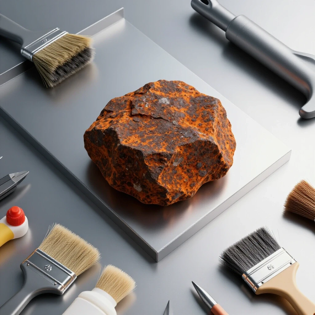
You cannot weld over rust or the dark grey coating on new steel called mill scale. Mill scale has a higher melting point than the steel beneath it. If you don’t grind it off, your weld will sit on top of the scale rather than penetrating the base metal. I always clear a zone at least one inch back from the weld area on all sides. This ensures that the heat of the arc doesn’t pull any “junk” into the molten puddle.
Why the Clean Zone Prevents Porosity
Porosity is a weld defect characterized by tiny holes or bubbles in the metal, often caused by trapped gases. These gases usually come from dirt, grease, or moisture on the surface of the steel.
I once spent a whole afternoon chasing “pinholes” in a frame I was building. I thought my gas flow was wrong, but it turned out I hadn’t cleaned the backside of the joint. The heat was pulling oils from the hidden side into the weld. Now, I use a dedicated wire brush and a flap disc to ensure every surface is shiny silver. If it isn’t bright and reflective, it isn’t ready to be welded.
Entry-Level Fusion Equipment and Parameter Setup
Fusion equipment refers to the machines used to melt and join metal, such as MIG or Stick welders. Setting the correct parameters—voltage and wire speed—is essential for achieving deep penetration and a smooth bead.
Many beginners struggle because they try to “eye-ball” their settings. I recommend starting with the manufacturer’s chart, usually found inside the wire drive door of your machine. However, those charts are just a starting point. You must learn to listen to the arc. A well-tuned MIG welder should sound like bacon frying in a pan. If it sounds like a machine gun, your wire speed is too high. If it’s a loud, erratic hiss, your voltage might be too high or your wire speed too low.
| Material Thickness | Voltage Setting (Approx) | Wire Speed (IPM) | Arc Gap/Stick-out |
|---|---|---|---|
| 16 Gauge (1/16″) | 15-16V | 180-200 | 1/4″ |
| 11 Gauge (1/8″) | 18-19V | 240-260 | 3/8″ |
| 3/16″ Plate | 20-21V | 300-320 | 3/8″ |
| 1/4″ Plate | 22-23V | 350-380 | 1/2″ |
Understanding the Relationship Between Volts and Amps
In simple terms, voltage controls the width and fluidity of the weld puddle, while amperage (or wire speed in MIG) controls the depth of penetration. Balancing these two is the key to a professional bead.
When I was learning, I would often turn the heat up too high because I thought “hotter is better.” All I ended up with was warped metal and holes. Think of voltage as the “spread” of the peanut butter and amperage as how deep the knife goes into the bread. You want a smooth, even spread that grips the base metal without cutting all the way through it.
Work Holding and Clamping Strategies
Work holding involves using clamps, magnets, and jigs to keep metal pieces in the correct position during the fabrication process. Proper clamping prevents the metal from moving or warping due to the intense heat of welding.
Metal expands when it gets hot and shrinks as it cools. If you don’t clamp your pieces firmly, they will “pull” toward the weld, ruining your 90-degree angle. I suggest owning at least four C-clamps and two locking pliers. Magnets are great for holding pieces in place initially, but they aren’t strong enough to resist the forces of thermal expansion. Always “tack” your pieces—meaning, make small, temporary welds at the corners—before doing the final bead.
- C-Clamps: Provide the highest pressure to keep parts flat against the table.
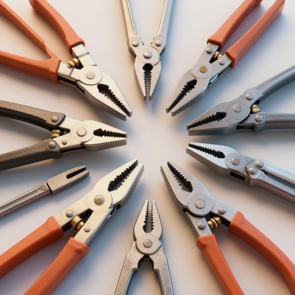
- Locking Pliers: Great for quick adjustments and holding small parts.
- F-Clamps: Offer a deeper reach for clamping in the middle of a large plate.
- Squaring Jigs: Homemade or store-bought tools that ensure a perfect 90-degree corner.
Managing Heat Warp with Strategic Clamping
Heat warp is the permanent deformation of a metal part caused by uneven heating and cooling. It is one of the most frustrating challenges for intermediate fabricators working on thin materials.
To combat this, I use a technique called “stitching.” Instead of running one long bead from end to end, I make a short weld on one side, move to the opposite end, and then weld the middle. This distributes the heat more evenly. Building on this, I keep my clamps on the piece until it is cool to the touch. The clamps act as a physical restraint, forcing the metal to stay straight while the internal stresses settle down.
Safety Gear as a Performance Tool
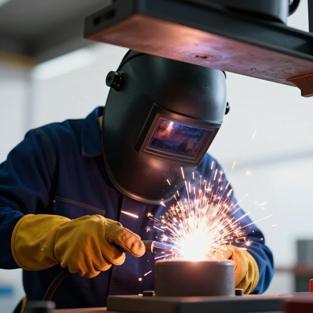
Personal Protective Equipment (PPE) includes items like helmets, gloves, and jackets that protect the fabricator from heat, light, and debris. Beyond safety, high-quality PPE improves your ability to see and control the weld puddle.
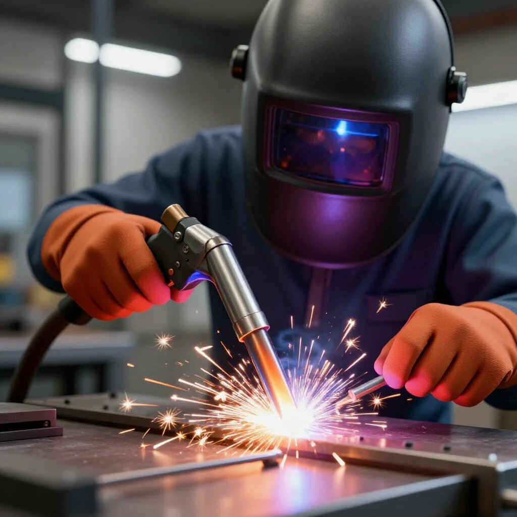
If you can’t see the puddle, you can’t weld. A cheap, fixed-shade helmet often makes the workspace too dark to see your layout lines before you start the arc. I recommend an auto-darkening helmet with a large viewing area. This allows you to see your torch placement clearly, which is vital for building muscle memory. Likewise, thin, flexible goatskin gloves provide better “feel” than thick, bulky cowhide, allowing for more precise torch manipulation.
Enhancing Visibility for Better Bead Control
Visibility is the ability to see the distinction between the molten metal (the puddle) and the solid metal (the joint). This is the most critical visual cue for any fabricator.
When I upgraded my helmet lens to a “true color” technology, my skill level jumped significantly. I could finally see the difference between the slag and the steel. Interestingly, many beginners struggle because they don’t have enough light in their shop. Adding a simple LED work light pointed directly at the joint can make a world of difference. If you can see the leading edge of the puddle, you can maintain a consistent arc length and travel speed.
Systematic Practice and Skill Tracking
Skill tracking is the process of recording your machine settings, travel speeds, and visual results to identify patterns in your progress. Using a logbook turns “guessing” into “data-driven improvement.”
I tell my students to keep a “Weld Log.” Every time you sit down to practice, write down the material thickness, the voltage, the wire speed, and how the weld felt. Did it feel too fast? Was the puddle sagging? After you finish a bead, take a photo of it. Over weeks and months, these records will show you exactly where you are plateauing and what adjustments helped you break through.
- Date and Material: Note the type of steel and its thickness.
- Machine Settings: Record volts, wire speed, and gas flow rate (CFH).
- The “Feel” Metric: Rate your hand stability on a scale of 1 to 10.
- Visual Inspection: Note the bead width, height, and any visible defects like undercut.
- The Fix: Write one thing you will change on the next pass.
Overcoming the Mid-Level Plateau
A plateau is a period where your skills seem to stop improving despite regular practice. This often happens once you master the basics but haven’t yet refined the “micro-motions” of the torch.
When I hit my first major plateau, I started using my phone to record slow-motion videos of my welding. By watching the video, I realized my torch angle was slowly tilting as I moved across the plate. I couldn’t feel it while I was welding, but the data on the screen was undeniable. Using video analysis is a modern way to diagnose technique errors that are too fast for the human eye to catch in real-time.
Conclusion: Your Roadmap to Consistency
Building a shop is not about buying the most expensive machines; it is about gathering the foundational shop equipment that allows you to practice with precision. By focusing on your body mechanics, using accurate layout tools, and maintaining a clean work zone, you remove the variables that cause frustration.
Consistency comes from repetition, but only if that repetition is structured. Start with simple bead-on-plate exercises. Master the 10-15 degree drag angle. Learn to maintain a 3/8-inch stick-out. Once those become second nature, move on to fillet welds and T-joints. The journey from a beginner to a professional-grade fabricator is a marathon of small, measured improvements. Keep your logbook close, keep your metal clean, and don’t be afraid to slow down and analyze your movements.
Frequently Asked Questions
What is the most common mistake beginners make with their torch angle? Most beginners tend to use an angle that is too steep or too flat. For MIG welding in the flat position, a 10 to 15-degree “drag” or “push” angle is ideal. If the torch is too vertical, you may lose visibility of the puddle. If it is too flat, you will lose shielding gas coverage and penetration, leading to a weak, porous weld.
How do I know if my travel speed is too fast or too slow? A bead that is too fast will look thin, stringy, and may have “undercut,” which is a groove melted into the base metal that isn’t filled. A bead that is too slow will be excessively wide, tall, and may “pile up” or even burn through the metal. Aim for a consistent width that is about 1.5 to 2 times the thickness of your electrode or wire.
Why is mill scale so difficult to weld through? Mill scale is a layer of iron oxide. It has a much higher melting temperature than the base steel and does not conduct electricity as well. Attempting to weld over it often results in “cold lap,” where the weld metal simply sits on top of the scale without actually fusing to the steel beneath it.
Do I really need a scribe, or can I just use a Sharpie? While a marker is fine for rough cuts, a scribe is essential for precision. A scribed line is much thinner and allows for a more accurate “kerf” (the width of the cut) calculation. If you want your parts to fit together without large gaps, the precision of a scribe is necessary.
What is the “bacon frying” sound people talk about? This refers to the sound of a Short-Circuit MIG weld when the voltage and wire speed are perfectly balanced. It is a consistent, crisp crackle. If the sound is interrupted by “pops,” your wire speed is likely too high. If it sounds like a hissing wind, your voltage is likely too high.
How often should I change my grinding discs? You should change a disc when it becomes glazed, chipped, or worn down to the point where the diameter is significantly reduced. A worn disc requires more pressure to use, which increases the risk of the tool kicking back or the disc breaking. Always inspect your discs for cracks before starting the grinder.
Why do my welds look different at the end of the joint than at the beginning? This is usually caused by “heat soak.” As you weld, the base metal gets hotter, which means it requires less energy to melt. If you maintain the same travel speed, the puddle will get wider and more fluid toward the end. To compensate, many fabricators slightly increase their travel speed as they reach the end of a long joint.
Is an auto-darkening helmet worth the extra cost? Yes, especially for beginners. An auto-darkening helmet allows you to keep both hands on your tools and see exactly where your torch is positioned before you strike the arc. This prevents “arc strikes” outside the joint and helps you start your bead exactly where you intended.
What is the best way to practice without wasting expensive metal? Use “bead-on-plate” drills. Take a single piece of scrap plate and run parallel beads across the surface. This allows you to focus purely on your travel speed and torch angle without worrying about joint fit-up. You can flip the plate over and use both sides, maximizing your practice material.
How can I tell if I have good penetration? On a butt joint, you should see a small “heat tint” or a slight bulge of metal on the backside of the plate. This indicates that the weld has melted all the way through the thickness of the material. If the backside looks untouched, you likely need more amperage or a slower travel speed.
(This article was written by one of our staff writers, Thomas Langley. Visit our Meet the Team page to learn more about the author and their expertise.)