How to Keep Heavy Square Tubing Tables Aligned (DIY Guide)
I remember the first time I tried to build a heavy-duty workbench. I had my square tubing cut, my welder hummed with promise, and I spent hours meticulously measuring every corner. By the time I finished the final pass on the last joint, I realized one leg was nearly half an inch off the ground. The heat from my welds had pulled the entire frame into a subtle, frustrating twist. It was a humbling moment that taught me a vital lesson: building a flat, true work surface is less about the final weld and more about managing the physical forces of heat and geometry from the very first spark.
Learning metal fabrication is a journey of developing muscle memory and technical intuition. When you are working with heavy-duty steel, you aren’t just joining two pieces of metal; you are managing a living material that expands and contracts. My own progression from a frustrated hobbyist to a disciplined fabricator involved tracking every mistake. I started logging my travel speeds, my heat settings, and the order of my tacks. This systematic approach is what I want to share with you today. We are going to look at how to maintain structural integrity and precision in your builds by focusing on the mechanics of the process.
Establishing Proper Body Mechanics and Workspace Ergonomics
Body mechanics in fabrication refers to the way you position your torso, arms, and hands to ensure maximum stability and torch control. Proper ergonomics reduces fatigue and allows for the fluid, consistent movements necessary for high-quality welds. It is the physical foundation upon which all other technical skills are built.
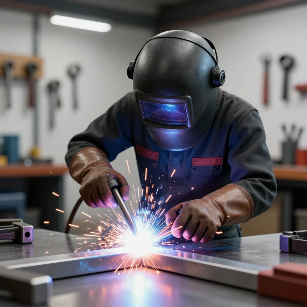
When I first started, I would often find myself hunched over a joint, holding my breath, and tensing my entire shoulder. This tension is the enemy of a steady hand. To master torch control, you must find a way to brace yourself. I advocate for the “three points of contact” rule. If you are standing, keep your feet shoulder-width apart, lean your non-welding hip or shoulder against the bench, and use your off-hand to steady your welding wrist. This creates a tripod of stability that isolates your hand movement from your body’s natural micro-swings.
In your trade school practice drills, focus on “dry runs.” Before you pull the trigger, move your torch along the entire length of the joint. Ensure your elbow won’t hit a clamp and your lead won’t snag. If you feel any resistance in your range of motion, reposition your body before you start the arc. This physical preparation is what separates a professional-grade result from a shaky, inconsistent bead.
Calibrating Machine Parameters for Heavy Tubing
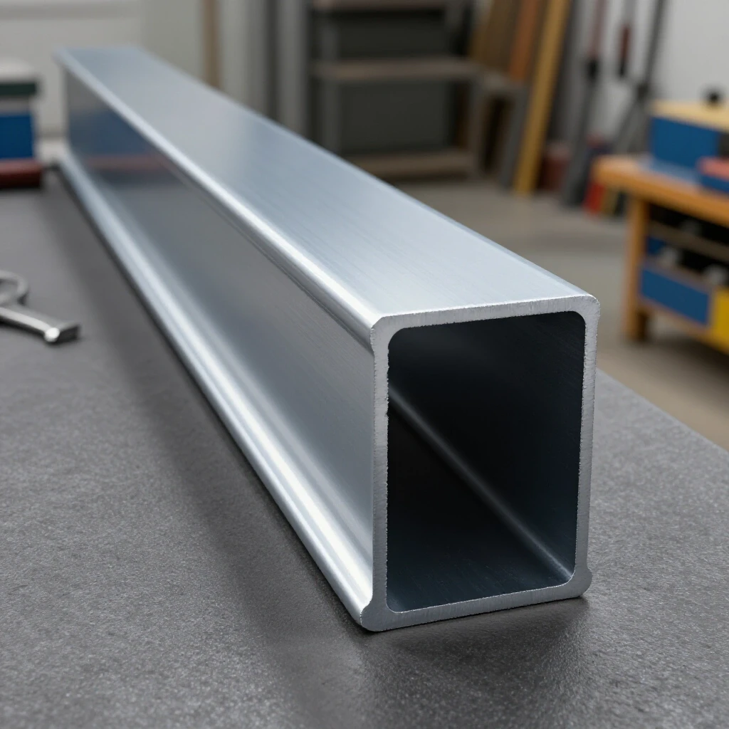
Setting baseline machine power involves adjusting your voltage and wire feed speed to match the thickness of your material. For heavy square tubing, usually 1/8 inch or 3/16 inch wall thickness, these parameters dictate how deeply the weld penetrates and how much heat is soaked into the frame.
A common mistake is simply “cranking it up” to ensure the metal stays stuck together. However, excessive heat is the primary cause of frame distortion. You need to find the “sweet spot” where the puddle is fluid enough to flow but not so hot that it causes the tubing to bow. For 1/8-inch wall tubing using .030 wire, I typically start my machine around 18-19 volts with a wire speed of 210-230 inches per minute.
| Material Thickness | Wire Diameter | Voltage Range | Wire Feed Speed (IPM) | Target Travel Speed |
|---|---|---|---|---|
| 1/8″ (11ga) | .030″ | 17 – 19V | 200 – 240 | 8 – 12 IPM |
| 3/16″ (7ga) | .035″ | 19 – 21V | 210 – 250 | 7 – 10 IPM |
| 1/4″ | .035″ | 21 – 23V | 280 – 320 | 5 – 8 IPM |
As part of your welding technique progression, keep a small notebook by your machine. Every time you finish a project, note the settings and the result. If the tubing pulled significantly to one side, you might need to lower your heat input or increase your travel speed in the next session.
Preparing Clean Zones and Material Layout
Preparing clean zones is the process of removing mill scale, oils, and rust from the area where the weld will be placed. A clean zone should extend at least one inch back from the edge of the joint. This ensures that the arc stays stable and the weld puddle remains free of contaminants.
In my early days, I thought a quick wipe with a rag was enough. I was wrong. Mill scale—that dark, flaky layer on hot-rolled steel—is an insulator. It forces you to use more heat to get the arc started, which in turn increases the risk of warping your frame. Use a flap disc or a wire wheel to grind the metal until it is bright and shiny. This is a non-negotiable step in any metal welding practice guide.
Once the metal is clean, the layout begins. Use a high-quality machinist square and a dedicated layout table if available. If your floor is uneven, do not rely on a level; rely on your squares and diagonal measurements. For a rectangular frame, the distance from the top-left corner to the bottom-right corner must be identical to the distance from the top-right to the bottom-left. If these numbers are even 1/16th of an inch off, your table will never be truly square.
Mastering Torch Control and Travel Speed
Travel speed is the rate at which you move the welding torch along a joint, measured in inches per minute (IPM). Mastering torch control involves maintaining a consistent arc length and a steady angle to ensure uniform heat distribution. This prevents the metal from overheating and pulling the frame out of alignment.
When welding square tubing, I recommend a 10 to 15-degree drag angle. This allows you to see the puddle clearly while pushing the heat into the base of the joint. Your arc gap—the distance between the tip of the wire and the metal—should be between 3/32″ and 1/8″. If you pull too far away, the arc becomes unstable and the heat spreads too wide.
- Practice Drill: Take a scrap piece of tubing and draw a straight line with a soapstone. Practice moving the torch along that line at a steady 10 IPM. Count “one-one-thousand, two-one-thousand” for every inch you move.
- Visual Cues: Watch the “toes” of the weld. If the puddle is wider on one side, your torch angle is tilted. If the puddle looks like a pointed arrowhead, you are moving too fast. If it is a perfect circle, you are likely moving too slow and dumping too much heat into the steel.
Strategic Tack-Welding Sequences
A tack-welding sequence is the specific order in which you place small, temporary welds to hold a structure together before final welding. These tacks act as “anchors” that resist the pulling forces generated as the metal cools. A strategic sequence is the most effective way to keep a heavy frame flat.
Never weld one corner completely before moving to the next. This is a recipe for a twisted frame. Instead, place a small tack on the inside of every corner. Then, check your squareness again. If the frame has moved, you can easily break a small tack and reposition. Once the frame is square, place tacks on the outside corners.
I use a “diagonal balance” method. If I tack the front-left corner, my next tack goes to the back-right corner. This distributes the tension across the entire structure rather than concentrating it on one side. Think of it like tightening the lug nuts on a car tire; you always work in a cross-pattern to ensure everything seats evenly.
Managing Heat Input to Prevent Distortion
Heat input is the total amount of thermal energy transferred to the workpiece during the welding process. It is a function of voltage, amperage, and travel speed. Managing this input is critical because as metal cools, it shrinks, and that shrinkage is what pulls heavy tubing out of its intended position.
One of the most effective tips I can give is to “stitch” your welds. Instead of running a continuous bead along a three-foot span, weld in short 2-inch or 3-inch sections. Move to a different part of the table to let the first section cool. This keeps the overall temperature of the tubing lower.
Interestingly, the more metal you add, the more it will pull. Avoid making excessively large fillet welds. If the wall of your tubing is 1/8″, your weld bead doesn’t need to be 1/2″ wide. A weld that is roughly the same thickness as the base metal is usually sufficient for structural integrity without causing unnecessary distortion.
Implementing Internal Bracing and Gussets
Internal bracing and gussets are additional steel components added to the corners or spans of a frame to increase rigidity. These parts serve as mechanical stops that prevent the tubing from bowing under the weight of a heavy work surface or the stress of welding.
For heavy-duty benches, I always recommend adding triangular gussets to the corners. These should be cut from the same thickness of plate as your tubing wall. Tack them into place after the main frame is squared but before you perform the final “hot” passes. These gussets act like a permanent square, locking the 90-degree angle in place.
- Cross-Bracing: If your table is long (over 5 feet), add a center support beam. This prevents the long spans of tubing from sagging or “crowning” in the middle.
- Placement: Ensure your braces are perfectly centered. If a brace is offset to one side, the heat from its welds will pull the main rail toward that side, creating a curve in your table edge.
Post-Assembly Corrections and Fine-Tuning
Post-assembly corrections are the techniques used to fix minor misalignments after the welding is complete. Even with perfect technique, some movement is inevitable. Methods like shimming or heat straightening allow you to bring a frame back into a professional-grade tolerance.
If you find a slight wobble, you can use thin steel shims between the frame and the tabletop surface. However, I prefer “heat shrinking” for structural corrections. If a rail is bowed upward, you can apply a small amount of heat with a torch to the top of the curve. As that spot cools, it will shrink and pull the rail back down toward a flat position. This is an advanced skill that requires patience; always let the metal cool naturally rather than quenching it with water, which can make the steel brittle.
Another trick is to use a heavy-duty clamp and a “strongback”—a known straight piece of heavy I-beam or thick tubing. Clamp your warped piece to the straight one, over-bending it slightly in the opposite direction, and then apply a small weld or heat. When you release the clamp, the metal often “springs” back to the desired flat position.
Tracking Progress with a Fabrication Log
A fabrication log is a structured record of your projects, including measurements, machine settings, and reflections on what went wrong or right. It is the most powerful tool for overcoming technique plateaus and identifying patterns in your work.
I encourage my students to use a simple numbered list for every project: 1. Initial Diagonal Measurements: (e.g., 42 1/8″ and 42 1/8″) 2. Machine Settings: (e.g., 18.5V, 220 IPM) 3. Tack Sequence Used: (e.g., Cross-pattern, 4 tacks per joint) 4. Post-Weld Deflection: (e.g., 1/16″ twist in the back-right corner) 5. Notes for Next Time: (e.g., Increase travel speed on the final passes to reduce heat soak)
By reviewing these logs, you can see if your consistency is improving. If you notice that your frames always pull to the left, you might realize you are always welding from left to right without alternating sides. This data-driven approach removes the guesswork from learning metal fabrication.
Final Benchmarks for Professional Results
To know if you have succeeded, you need objective benchmarks. For a heavy-duty shop table, a professional-grade result usually means the surface is flat within 1/16th of an inch across the entire span. Corners should be within 0.5 degrees of a perfect 90-degree angle.
When you inspect your work, look for visual defects. Is there undercut (a groove melted into the base metal)? Are the beads consistent in width? Consistency is the hallmark of a skilled fabricator. If your first bead looks different from your last, it means your body position or your hand-eye coordination shifted during the process.
The goal isn’t to be perfect on day one. The goal is to be better on day one hundred than you were on day ten. By focusing on these structured physical practice cycles and maintaining a rigorous layout routine, you will eventually find that keeping a heavy structure aligned becomes second nature.
Frequently Asked Questions
Why does my square tubing always twist after I finish welding the corners? Metal expands when heated and contracts as it cools. When you weld a corner, the cooling weld bead acts like a powerful spring, pulling the ends of the tubing toward the center of the weld. If you weld one side of a frame completely before moving to the other, the cumulative pull will twist the entire structure. Use a cross-tacking sequence to balance these forces.
How many tacks should I use on a 2-inch square tube joint? I recommend at least four tacks per joint—one in the center of each of the four sides. For heavy-duty frames, place the tacks about 1/4 inch away from the actual corners. This allows the corners to remain accessible for the final welding passes while providing enough strength to hold the geometry during the process.
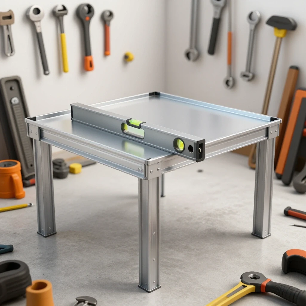
Can I use a level to make sure my table frame is flat? A level is only as accurate as the floor it sits on. Unless you are working on a precision-ground machinist’s floor, a level can be misleading. It is much better to use a “string test” or a long, known-straight edge (like a 6-foot levels used as a straightedge) to check for gaps between the edge and the tubing.
What is the best way to fix a leg that is slightly shorter than the others? Instead of cutting the leg, it is often easier to use adjustable leveling feet. If you want a solid connection, you can weld a thick plate to the bottom of the short leg and grind it to the correct height. Always check the squareness of the frame before assuming the leg length is the problem; a twist in the top frame often makes legs appear uneven.
Does the thickness of the tubing wall change how I should weld it? Absolutely. Thinner walls (like 16 gauge) require much faster travel speeds and lower heat to prevent “blow-through.” Heavier walls (like 3/16″ or 1/4″) require more heat and a slower travel speed (around 6-8 IPM) to ensure the weld penetrates deep into the root of the joint.
Should I weld the top or the sides of the frame first? I prefer to weld the vertical sides of the joints first. This locks the uprights into place. If you weld the top surfaces first, the heat often pulls the legs inward, making it very difficult to get the side welds to line up correctly later.
How do I prevent the “bowing” effect on long spans of tubing? This is caused by heat soak. To prevent it, use “back-stepping.” Instead of welding from point A to point B, start an inch away from point B and weld toward it. Then move back another inch and weld toward your previous start point. This breaks up the heat and prevents a continuous wave of expansion from bowing the rail.
What should I do if I accidentally blow a hole in the tubing? Stop immediately and let the area cool. Do not try to fill the hole while the metal is glowing red, or you will just make it bigger. Once cool, use short “trigger pulls” to build up a bridge of metal across the hole, then grind it flat and re-weld the area with the correct settings.
Is it better to MIG or TIG weld a heavy shop table? MIG is generally preferred for heavy frames because it is faster and puts less total heat into the metal over a long period compared to TIG. However, TIG allows for much more precise control if you are working with thinner-walled tubing where distortion is a major concern.
How do I know if I have enough penetration on my welds? On square tubing, you should look for a slight “heat tint” or discoloration on the inside of the tube if possible. If the weld bead is sitting high on top of the metal like a cold piece of gum, you don’t have enough heat. If the bead is flat and the edges are “wetted” into the base metal, your penetration is likely sufficient.
(This article was written by one of our staff writers, Thomas Langley. Visit our Meet the Team page to learn more about the author and their expertise.)