Essential Precision Measuring Tools for Metal Lathes (Review)
I have spent two decades refining the way metal moves through my shop. In the early days, I was happy if a part looked right and fit “close enough.” As I transitioned from a hobbyist to a micro-manufacturer, I realized that “close enough” was the primary bottleneck in my production. Scaling a fabrication business isn’t just about buying bigger machines; it is about mastering the physics of the work itself. When you are running a manual lathe in a high-output environment, your ability to hit a dimension within half a thousandth of an inch determines your scrap rate and your reputation.
The stress of scaling often comes from the fear of a “bad batch.” You worry that after hours of turning, a final measurement will reveal a part that is undersized. I have found that the solution lies in the systematic integration of high-level inspection instruments. By treating measurement as a core part of the workflow rather than an afterthought, we can eliminate the “back-and-forth” travel waste that kills shop throughput.
Strategic Layout of the Turning Center for Quality Control
Machine zoning is the practice of organizing a workspace so that all necessary components for a specific task are within immediate reach. In a manual turning environment, this means creating a dedicated inspection station directly adjacent to the lathe. This setup minimizes the physical travel of the operator, which reduces fatigue and prevents measuring errors caused by environmental changes.
When I redesigned my shop layout, I focused on the “three-foot rule.” Every tool needed to verify a cut must be within three feet of the lathe carriage. This isn’t just about saving steps; it is about temperature stability. If you take a hot part off the lathe and walk across a drafty shop to a granite plate, the metal will contract. By measuring at the machine with tools stored in the same ambient temperature, you maintain a consistent baseline.
I also look at floor load ratings and vibration isolation. A lathe is a precision instrument, but it is also a source of vibration. If your measuring tools are stored on a bench bolted to the same floor as a heavy mill or a vibrating air compressor, your dial indicators may show ghost movements. I recommend using high-density rubber matting or isolated tool cabinets to ensure your instruments stay true.
| Layout Feature | Purpose | Impact on Precision |
|---|---|---|
| Dedicated Tool Shadow Board | Visual management of instruments | Reduces search time and prevents tool damage. |
| Task Lighting (500+ Lux) | High-visibility work zone | Allows for accurate reading of vernier scales. |
| Climate-Controlled Storage | Thermal stability for tools | Prevents 0.0001″ deviations due to expansion. |
| Vibration-Damping Mounts | Isolates measuring bench | Ensures dial indicators remain steady during readings. |
Mastering Diameter Verification with Outside Micrometers
An outside micrometer is a screw-based instrument that measures external dimensions by translating the rotation of a calibrated thread into linear distance. It is the primary tool for achieving tolerances between 0.001 and 0.0005 inches. In a professional shop, the micrometer is the final authority on whether a shaft meets the required engineering specifications.
I have learned that using a micrometer is as much about “feel” as it is about the tool itself. Most high-quality micrometers feature a ratchet stop or a friction thimble. This mechanism ensures that the same amount of pressure is applied to the part every time you take a measurement. Without this, one operator might tighten the tool more than another, leading to inconsistent readings. In a lean operation, consistency is more important than speed.
When you are turning long shafts, thermal expansion is your biggest enemy. If I am taking a heavy roughing cut, the workpiece will get hot. If I measure it immediately, the reading will be larger than the actual size once the part cools. I always suggest a “cooling soak” or using a dedicated coolant system to keep the part at a stable temperature before the final finishing pass. This ensures that the 2.000-inch diameter you measure at the lathe is still 2.000 inches when it reaches the customer.
- Always zero your micrometer at the start of every shift using a standard reference gauge.
- Clean the measuring faces (the anvil and spindle) with a piece of lint-free paper before use.
- Hold the micrometer by the insulated frame to prevent your body heat from expanding the metal tool.
- Use a micrometer stand when measuring small parts to ensure the tool is perfectly perpendicular to the workpiece.
Dial Indicators and Magnetic Bases for Mapping Concentricity
A dial indicator is a sensing instrument that measures small linear distances by converting the movement of a plunger into the rotation of a needle. When paired with a magnetic base, it becomes a versatile tool for checking the alignment of a workpiece in a four-jaw chuck or measuring the runout of a spindle. This is the first line of defense against “wobble” in your finished parts.
In my experience, the setup of the magnetic base is where most errors occur. If the arms of the base are extended too far or are not tightened properly, the assembly can flex. This flex introduces “sine error,” where the needle moves because the tool is moving, not because the part is out of round. I teach my team to keep the indicator arms as short and rigid as possible. This ensures that the 0.0005-inch movement on the dial is a true reflection of the part’s geometry.
Beyond simple alignment, dial indicators are essential for “facing” operations. If you need to ensure a flange is perfectly square to the axis of rotation, you sweep the face with the indicator. This process highlights any tilt or “dish” in the cut. For a shop scaling into more complex assemblies, mastering the dial indicator is the difference between a part that fits and a part that binds.
- Verify that the magnetic base is secured to a clean, flat surface to prevent rocking.
- Check for “stickiness” in the plunger; it should move smoothly without any gritty feeling.
- Position the indicator tip so it is as close to 90 degrees to the surface as possible to avoid cosine error.
- Use a “test indicator” (lever type) for small spaces or internal surfaces where a plunger style won’t fit.
Telescoping Gauges and Internal Measurement Strategies
Telescoping bore gauges are T-shaped instruments used to transfer the internal dimension of a hole to an outside micrometer. They consist of two spring-loaded plungers that expand to touch the walls of a bore. Because they do not have a built-in scale, their accuracy depends entirely on the operator’s ability to “feel” the high point of the diameter.
I often see fabricators struggle with internal bores because they rely on calipers, which can easily tilt inside a hole. The telescoping gauge solves this by being self-centering to an extent. However, the technique involves a specific rocking motion. You lock the plungers slightly larger than the hole, compress them, insert them, and then “sweep” the gauge through the center of the bore. This finds the true diameter.
Once the gauge is locked at the widest point, you carefully remove it and measure the tips with an outside micrometer. This “transfer” method is a classic toolroom skill. While it takes longer than a digital tool, it provides a level of accuracy that is hard to beat for the cost. In a shop where we are optimizing for both cost and precision, these gauges are indispensable for boring operations like bearing seats or press-fit sleeves.
- Select a gauge that is in the middle of its expansion range for the best spring tension.
- Clean the bore thoroughly; even a small chip will throw off the reading by several thousandths.
- Rock the gauge gently across the axis to ensure you are measuring the true center, not a chord.
- Repeat the measurement three times to ensure your “feel” is consistent before committing to the final cut.
Calipers in a Professional Environment: Speed vs. Precision
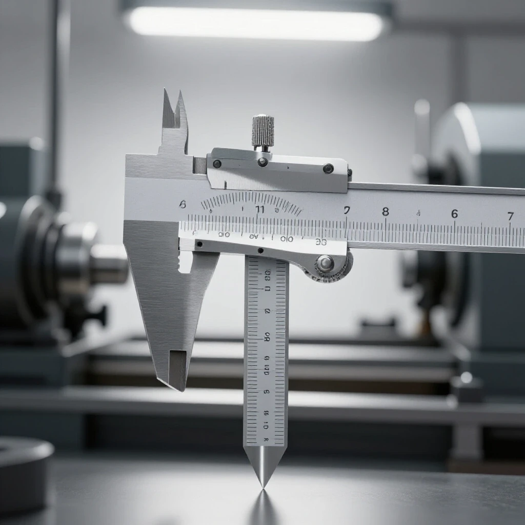
A caliper is a versatile tool used for measuring internal, external, and depth dimensions. While they are the “workhorse” of any shop, they have limitations in a high-precision turning environment. A standard digital or vernier caliper is generally reliable to about 0.002 inches, which is often not enough for critical lathe work.
I use calipers for “roughing in” my parts. When I am taking large passes and I just need to know if I am within a sixteenth of an inch of my target, the caliper is the fastest tool for the job. It allows for quick checks of shoulder lengths and overall part dimensions. However, I have a strict rule in my shop: never use a caliper for a final bearing fit. The jaws of a caliper can flex if you apply too much pressure, giving you a false sense of security.
When you are scaling your operations, you have to decide where speed is an asset and where it is a liability. Using a caliper to check a critical diameter is a liability. Using it to verify the length of a hex-head bolt is an asset. By defining these boundaries, you create a workflow that is both fast and accurate.
| Measurement Task | Recommended Tool | Accuracy Expectation |
|---|---|---|
| Rough Diameter Turning | Digital Caliper | +/- 0.002″ |
| Final Bearing Fit | Outside Micrometer | +/- 0.0002″ |
| Checking Bore Roundness | Telescoping Gauge + Mic | +/- 0.001″ |
| Aligning Workpiece in Chuck | Dial Indicator | +/- 0.0005″ |
Maintaining Measurement Standards in a High-Output Shop
Precision instruments are only as good as the systems used to maintain them. In a busy shop, tools get dropped, exposed to grinding dust, and subjected to temperature swings. I treat my measuring tools like the “brain” of the operation. If the brain is foggy, the whole shop suffers.
I recommend a simple calibration log. Every Monday morning, before any chips fly, we check our micrometers against their standards and our indicators against a known flat surface. This five-minute habit prevents hours of rework later in the week. If a tool is dropped, it is immediately pulled from service until it can be verified. This is a core “lean” principle: stop the line to fix a quality issue before it multiplies.
Cleanliness is another factor often overlooked. In shops with heavy welding or grinding, fine metallic dust can settle on the precision threads of a micrometer. This dust acts as an abrasive, wearing down the tool and destroying its accuracy. I keep all my precision instruments in closed cases or a dedicated “clean cabinet” away from the primary fabrication area. This extends the life of the tool and ensures the readings remain reliable over years of heavy use.
- Store tools in their original foam-lined cases to prevent accidental bumps.
- Apply a very light coat of high-quality instrument oil to prevent rust on non-painted surfaces.
- Never store micrometers with the anvils touching; leave a small gap to allow for thermal expansion.
- Use a dedicated “checking station” with a surface plate that is kept covered when not in use.
Eliminating Bottlenecks Through Measurement Efficiency
In my transition from a small-scale fabricator to a more professional operator, I realized that the biggest bottleneck wasn’t the speed of the lathe—it was the time spent doubting the measurements. When you lack confidence in your tools, you tend to “sneak up” on a dimension, taking dozens of tiny, inefficient cuts.
By investing in high-quality instruments and mastering their use, you can take bolder, more efficient passes. You know exactly how much material is left because your measurement is a fact, not a guess. This confidence allows you to optimize your material flow. You can move from roughing to finishing with fewer stops, which increases your hourly output.
I also focus on lighting. It sounds simple, but many measurement errors happen because the operator is squinting at a vernier scale in a dimly lit corner. I installed high-intensity LED task lighting at every machine. This reduces eye strain and makes it much easier to see if a needle is truly on the zero mark. When you make the right way the easy way, your shop’s overall efficiency naturally climbs.
Common Mistakes in Manual Lathe Measurement
One of the most frequent errors I see is failing to account for “tool pressure.” When a cutting tool is pushed against a workpiece, the metal actually deflects slightly. If you measure the part while it is still under tension or if you haven’t taken a “spring pass” (a final pass without changing the depth of cut), your measurement will be inaccurate.
Another mistake is neglecting the “zero” of the tool. I have seen experienced guys pull a micrometer out of a drawer and start measuring without checking it against a standard. A piece of lint or a small temperature change can throw a micrometer off by 0.001 inches. In the world of precision machining, that is a massive error. Always verify the tool before the measurement.
Finally, avoid the “death grip” on your instruments. Precision measuring is a delicate process. If you are white-knuckling a micrometer, you are likely distorting the frame or the part. Use a light touch. The goal is to find the point where the tool just kisses the surface of the metal. This “sensitivity” is what separates a master fabricator from a hobbyist.
- Forgetting to deburr the part before measuring (a tiny burr can add 0.005″ to a reading).
- Measuring a part while it is still spinning (this is dangerous and ruins the tool).
- Using the wrong range tool (e.g., using a 1-2″ micrometer for a 0.9″ part).
- Ignoring the parallax error (reading the dial or scale from an angle rather than straight on).
FAQ: Precision Measurement in the Manual Shop
How often should I calibrate my manual measuring tools? In a high-output shop, I recommend a quick “zero check” at the start of every shift. A more formal calibration against certified standards should happen once a month, or immediately if a tool is dropped or subjected to an extreme temperature change.
Can I use digital calipers for everything on the lathe? No. Digital calipers are excellent for speed and general dimensions, but they lack the rigidity and resolution for bearing fits or precision press-fits. For anything requiring a tolerance tighter than 0.002 inches, an outside micrometer is necessary.
What is the best way to measure a deep internal bore? Telescoping bore gauges are the most cost-effective way for deep bores. They allow you to reach far into a part and transfer that dimension to a micrometer. For very high-precision work, a dedicated dial bore gauge is better but significantly more expensive.
Why does my micrometer give different readings on the same part? This is usually due to “operator feel” or thermal expansion. Ensure you are using the ratchet stop for consistent pressure and that the part has cooled to room temperature. Also, check that the measuring faces are perfectly clean.
Do I really need a magnetic base for my dial indicator? Yes. A dial indicator must be held perfectly rigid relative to the machine to provide an accurate reading. Trying to hold an indicator by hand or with a flimsy setup will result in “noise” that makes it impossible to see true runout.
Is there a difference between a “test indicator” and a “plunger indicator”? Yes. A plunger indicator is for measuring linear travel (like the depth of a cut). A test indicator (lever type) is for measuring deviations in a surface (like runout or squareness). You generally need both for a complete lathe setup.
How do I prevent my tools from rusting in a humid shop? Keep them in their cases with a small VCI (Vapor Corrosion Inhibitor) chip or apply a light film of specialized instrument oil. Never store them wet or covered in coolant, as the chemicals can etch the precision surfaces.
What should I do if my dial indicator starts sticking? Do not use WD-40 or heavy oils, as they will attract dust and eventually gum up the mechanism. Use a dedicated electronic cleaner or a very light watch oil, or send it to a professional for cleaning. Often, a sticking plunger is caused by fine metal dust that needs to be blown out with dry air.
Why is my workpiece “out of round” even though my lathe is level? This is often a work-holding issue. If you over-tighten a three-jaw chuck on thin-walled tubing, the part will deform. When you measure it in the chuck, it might look round, but once you release the pressure, it “springs” back into a triangular shape. Use a dial indicator to check for this “spring” after loosening the chuck slightly.
How can I measure a taper accurately on the lathe? The best way is to use a “sine bar” or to take measurements at two known points along the length of the taper using a micrometer. By calculating the difference in diameter over the distance between the two points, you can determine the exact angle of the taper.
Moving Toward a Semi-Professional Standard
The transition from a hobby shop to a semi-professional fabrication space is built on the foundation of measurement. When I look back at my most successful projects, they weren’t successful because I had the most expensive lathe. They were successful because I had the right tools to verify my work at every step of the process.
If you are looking to scale your operations, start by auditing your measurement workflow. Look for the “travel waste” in your layout. Ensure your tools are within reach and that your lighting is sufficient. By treating your micrometers and indicators with the same respect as your primary machinery, you reduce scrap, save time, and build a reputation for quality that will sustain your business for years to come.
Your next step should be a simple one: go to your lathe station and look at where your measuring tools are stored. If they aren’t within arm’s reach of the carriage, move them. If you don’t have a standard to check your micrometer against, buy one. These small, data-driven changes are the essence of lean manufacturing, and they are the key to evolving your shop into a high-efficiency production environment.
(This article was written by one of our staff writers, Edward Sinclair. Visit our Meet the Team page to learn more about the author and their expertise.)