Batch Production vs Custom Metal Fabrication (Comparison)
I remember the exact moment I realized my workshop was no longer working for me. I was tripping over a stack of laser-cut brackets while trying to weld a one-off structural frame for a local contractor. My shop, which I had built over twenty years, was caught in the “messy middle.” I was trying to balance the high-speed demands of repetitive part runs with the slow, meticulous requirements of unique, bespoke builds. The floor was a maze, the air was thick with grinding dust, and my single-phase power was screaming under the load.
Scaling a fabrication business is not just about buying faster machines. It is a fundamental shift in how you think about space, power, and time. When you move from making whatever comes through the door to managing a high-output facility, the physics of your shop must change. You are no longer just a fabricator; you are a process engineer. This transition requires a hard look at your layout, your electrical capacity, and how you handle the literal air you breathe.
Mapping Material-Flow Loops for Scalability
Material-flow mapping is the process of tracing the physical path a piece of steel takes from the moment it enters your shop until it leaves as a finished product. In a high-output environment, every foot of travel adds “hidden” costs in labor and time. Mapping these loops helps you visualize where your shop layout is helping or hurting your bottom line.
When I first audited my shop, I used a simple “spaghetti diagram.” I drew my floor plan and used a red pen to trace my steps for a typical day. The result looked like a ball of yarn. I was walking back and forth between the material rack and the saw, then across the room to the welder, then back to the middle for the drill press. For one-off projects, this is annoying. For a run of 500 parts, it is a financial disaster.
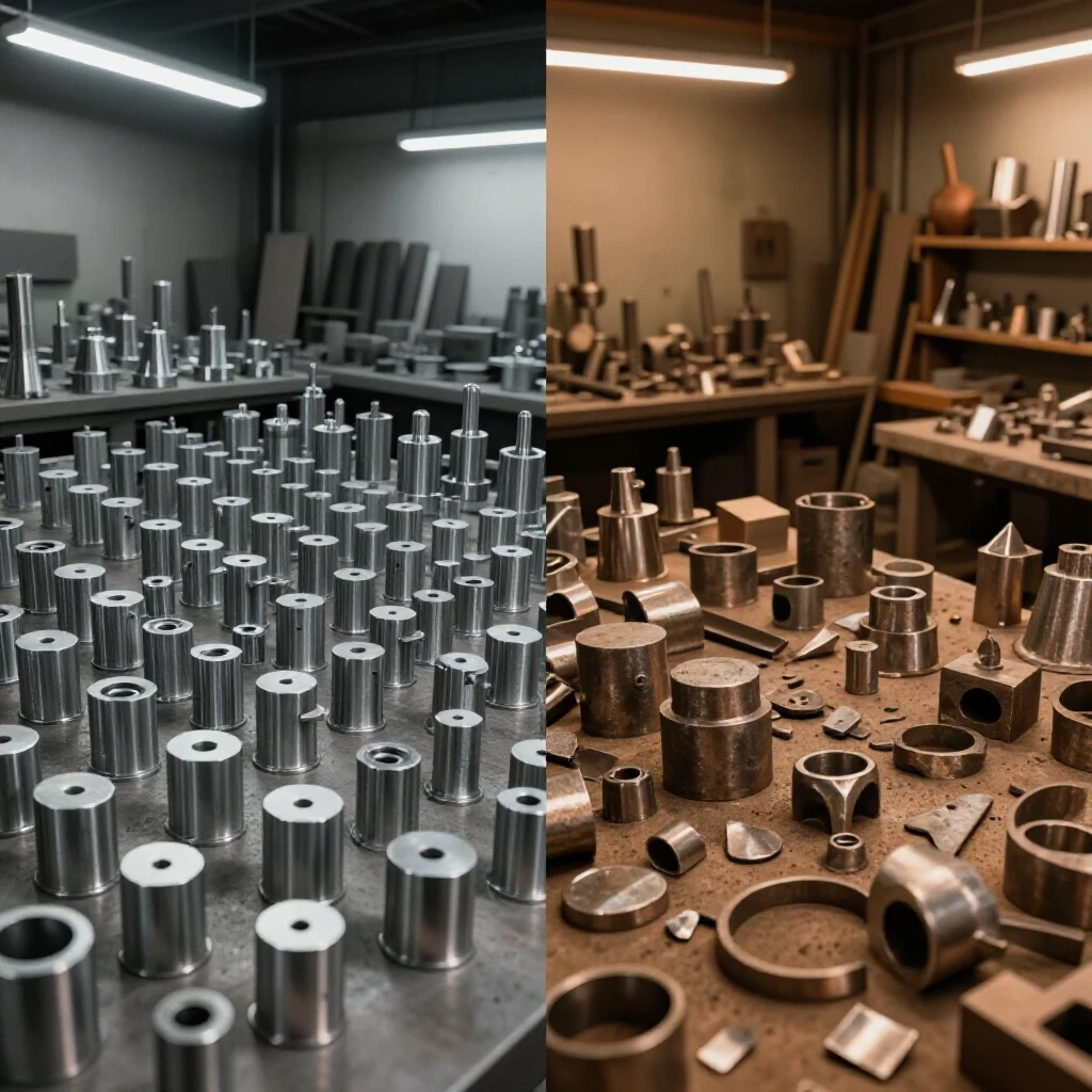
To optimize for high-volume throughput, you need to transition to a linear or “U-shaped” flow. In a linear flow, raw material enters at one end, moves through cutting, deburring, bending, and welding, and ends at a shipping station. This minimizes the “back-and-forth” that eats up your day. If you are focused on unique, complex builds, a “cell-based” layout often works better. Here, you group all necessary tools for a specific task—like a dedicated stainless welding station—in one area to reduce setup times.
| Feature | Repetitive Run Layout (Linear) | Bespoke Project Layout (Cellular) |
|---|---|---|
| Primary Goal | Minimize travel distance | Maximize tool accessibility |
| Material Handling | Roller tables and conveyors | Overhead hoists and carts |
| Station Setup | Fixed, single-purpose | Flexible, multi-tool |
| Throughput Speed | High per-unit speed | Variable based on complexity |
Why Back-and-Forth Foot Traffic Kills Shop Throughput
Foot traffic inefficiency refers to the wasted time spent moving people or materials through a poorly planned space. In a professional fabrication setting, movement that does not add value to the metal is considered “waste.” Reducing this waste is the fastest way to increase your shop’s capacity without buying a single new tool.
I once tracked a project where we had to move 40lb plates from the CNC plasma table to a finishing station 40 feet away. Over a week-long run, my assistant walked nearly three miles just carrying steel. We fixed this by installing a simple gravity roller conveyor between the two stations. We didn’t work harder; we just stopped walking so much.
For an advanced workshop layout, aim for a 3-foot minimum access zone around every major machine. This isn’t just for safety; it allows for the use of pallet jacks or material carts. If your machines are packed so tightly that you can’t move a cart between them, you are forced to carry everything by hand. That is a bottleneck that will eventually limit your growth.
Floor Load Ratings and Machine Zoning
Floor load rating is the amount of weight your concrete slab can safely support, usually measured in pounds per square foot (PSF). Machine zoning is the strategic placement of equipment based on its weight, power needs, and the type of “mess” it creates. Ignoring these factors can lead to cracked floors or expensive electrical reruns later.
Standard residential garage slabs are often 4 inches thick, rated for about 3,000 to 4,000 PSI. While this sounds like a lot, a heavy CNC plasma table or a large press brake creates “point loads” that can exceed these limits. When I installed my first heavy-duty gantry system, I had to saw-cut the slab and pour a reinforced 6-inch pad to handle the vibration and weight.
- Heavy Zone: Place your heaviest equipment (CNC tables, ironworkers) near the thickest part of the slab, usually near the main door.
- Dirty Zone: Group grinding, sanding, and plasma cutting together. This makes dust collection much more efficient.
- Clean Zone: Keep your precision welding and CAD workstations as far from the “Dirty Zone” as possible.
Powering the Evolution with 3-Phase Systems
A 3-phase power system provides three alternating currents that are out of phase with each other, resulting in more consistent and efficient power delivery for industrial motors. Most home-based shops start with single-phase power, but high-output machinery often requires 3-phase to run efficiently and coolly.
When you scale, you will eventually hit a wall with single-phase power. Large compressors and CNC spindles thrive on 3-phase. You have three main options: a Rotary Phase Converter (RPC), a Variable Frequency Drive (VFD), or a Digital Phase Converter. I started with an RPC because it was rugged and could handle the high “inrush” current of starting a large motor. However, RPCs are noisy and consume power even when you aren’t using the slave motor.
Digital phase converters are the gold standard for modern shops. They provide “clean” power, which is vital for the sensitive electronics in CNC controllers. They are more expensive upfront but offer better than 95% efficiency. In my shop, switching to a digital converter reduced my monthly power bill and stopped my CNC plasma cutter from throwing “low voltage” errors during heavy cuts.
| Converter Type | Best Use Case | Efficiency | Relative Cost |
|---|---|---|---|
| VFD | Single motor (lathe/mill) | High | Low |
| Rotary (RPC) | Multiple motors, high surge | Medium | Moderate |
| Digital | CNC electronics, high precision | Very High | High |
Designing High-Volume Clean Air Filtration
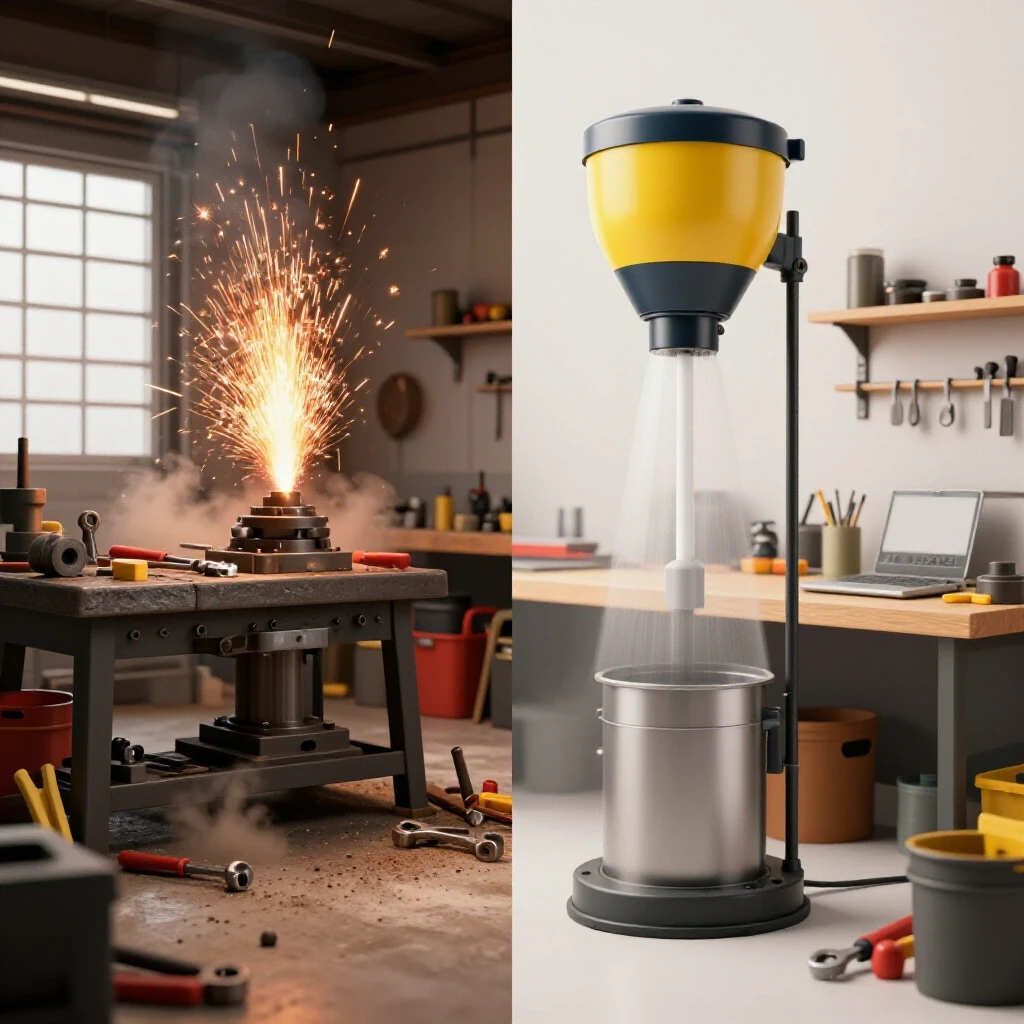
Air filtration in a fabrication shop involves removing hazardous fumes and particulate matter (dust) from the breathing zone. High-volume systems use a combination of source capture (fume arms) and ambient air “scrubbers” to maintain air quality. This is critical when transitioning to automated cutting, which generates significantly more smoke than manual methods.
A common mistake is underestimating the Cubic Feet per Minute (CFM) required. For a CNC plasma table, you need a water table or a “downdraft” system. A downdraft system typically requires 150 to 250 CFM per square foot of open table area to effectively pull smoke away. If you have a 4×8 table, you are looking at a 5,000 CFM blower. That is a massive amount of air to move and filter.
Duct design also matters. Use smooth-walled metal ducting instead of flexible ribbed hose. Every bend in the pipe creates “static pressure loss,” which reduces the actual suction at the tool. I use a simple rule: keep your main “trunk” line large and use 45-degree entries rather than 90-degree Ts. This keeps the air velocity high enough (around 3,500 to 4,000 feet per minute) so that heavy metal dust doesn’t settle and clog your pipes.
Integrating CNC Tooling into Daily Operations
CNC integration is the process of bringing computer-controlled machinery into your workflow to automate repetitive tasks. This involves not just the machine itself, but the “tooling files” and CAD/CAM software that tell the machine what to do. The goal is to move from “hand-crafted” to “program-controlled” production.
The learning curve here is steep. When I integrated my first CNC gantry, I spent more time at the computer than at the welding bench. For repetitive part runs, this investment pays off. You can “nest” dozens of parts on a single sheet of steel, hit “start,” and walk away to prep the next stage. This is the essence of workflow optimization tips: let the machine do the low-value repetitive work while you do the high-value assembly.
However, for one-off bespoke projects, the “setup-to-cut” ratio can be frustrating. If it takes you two hours to draw a part and set up the machine for a 30-second cut, you might have been faster using a bandsaw. Advanced shop owners balance this by building a library of “standard parts”—gussets, tabs, and flanges—that are ready to cut at a moment’s notice.
- Standardize your materials: Stick to a few common thicknesses to avoid constant machine recalibration.
- Organize your “Cut Library”: Keep a digital folder of every part you’ve ever designed.
- Use Closed-Loop Encoders: If your budget allows, choose motors with encoders. They “talk back” to the controller to confirm the machine actually moved where it was told, preventing ruined workpieces.
- Automate your Tool Paths: Use CAM software that can automatically apply “leads” and “kerf compensation” based on the material type.
The Economics of Scaling Your Throughput
Amortization is the process of spreading the cost of an expensive piece of equipment over its useful life. When choosing between high-volume runs and custom builds, you must understand how your equipment costs affect your per-part price. A $20,000 CNC table sounds expensive, but if it lasts 5 years and runs 2,000 hours a year, it only costs $2.00 per hour plus electricity and consumables.
In a high-output scenario, your goal is to maximize “spindle time” or “arc-on time.” Every minute the machine is sitting idle while you look for a wrench is lost revenue. In my shop, I tracked my “up-time” and realized I was only cutting 20% of the day. By reorganizing my material handling and using better software, I bumped that to 50%. That change alone doubled my shop’s capacity without adding a single square foot of floor space.
Custom fabrication, on the other hand, relies on a high hourly rate for your expertise. You aren’t selling “machine time”; you are selling “problem-solving.” The layout for this type of work needs to be flexible. You might need a large, flat welding table one day and a pipe bender the next. Your “return on investment” here comes from having the right tool available the moment you need it, rather than the raw speed of the tool itself.
Finalizing the Transition to Professional Operations
Moving from a hobbyist mindset to a professional manufacturing approach requires discipline. It means looking at your shop as a machine in itself. Every tool is a component, and every walkway is a circuit. If a component is failing or a circuit is blocked, the whole machine slows down.
Start by measuring your current state. How many feet do you walk to make a single part? How often does your breaker trip? How much dust is on your workbench at the end of the day? These metrics are the “before” in your before-and-after story. Once you have the data, you can make strategic choices about 3-phase power, air filtration, and CNC integration that actually move the needle.
The transition isn’t about working more hours; it’s about making the hours you work more productive. By applying lean principles and industrial-grade infrastructure to your home-based or micro-manufacturing shop, you create a space that can handle whatever comes through the door—whether it’s one unique masterpiece or a thousand identical parts.
Frequently Asked Questions
How do I know if I need a 3-phase power converter? You generally need 3-phase power if you are running industrial-grade motors over 5 or 7.5 horsepower. While some large motors can be run on single-phase with a VFD, a true 3-phase system is more efficient for shops running multiple machines like CNC mills, large air compressors, and heavy-duty welders simultaneously. If your single-phase breakers are constantly warm or your lights flicker when a motor starts, it is time to look at a converter.
What is the minimum CFM I need for a CNC plasma table? For a standard 4×8 downdraft table, you should aim for at least 4,000 to 5,000 CFM. This is based on the industry standard of moving air at approximately 150-250 feet per minute across the entire open surface of the table. A smaller 2×2 table might get by with 1,000 to 1,500 CFM. Always check the static pressure rating of your blower to ensure it can pull that air through your filters and ductwork.
Is a rotary phase converter better than a digital one for CNC machines? Digital phase converters are significantly better for CNC equipment. CNC controllers and servo drives are sensitive to voltage fluctuations and “dirty” power. A digital converter provides a perfectly balanced sine wave on all three legs, which protects your expensive electronics. Rotary converters are great for “dumb” motors like those on a manual lathe or saw, but they can cause issues with modern automated systems.
How much space should I leave between my machines for efficient flow? A good rule of thumb is a 3-foot “operator zone” around the work area of the machine and a 4-to-5-foot “transport lane” for moving materials. If you use pallet jacks or forklifts, your main aisles should be at least 6 to 8 feet wide. Proper spacing prevents bottlenecks and allows you to move raw materials in and finished products out without stopping other work in the shop.
What is the difference between “stepper” and “servo” motors on a CNC table? Stepper motors move in fixed “steps” and are generally more affordable, but they can “lose steps” if they hit an obstruction, leading to ruined parts. Servo motors use “closed-loop” feedback (encoders) to constantly tell the controller exactly where they are. If a servo motor is pushed off course, it will try to correct itself or trigger an emergency stop. For high-output shops, servos are worth the extra cost for the reliability they provide.
How do I calculate the static pressure loss in my dust collection system? Static pressure loss is calculated by adding the resistance of every foot of pipe, every elbow, and the filter itself. For example, a 90-degree elbow might have the same resistance as 10 feet of straight pipe. Most fabricators use online calculators or charts provided by ducting manufacturers. If your static pressure loss exceeds the “inches of water lift” your blower can handle, your air velocity will drop, and dust will settle in your pipes.
Should I prioritize a linear layout or a cellular layout? Choose a linear layout if you are doing high-volume runs of the same or very similar parts. It is the most efficient way to move “mass” through a shop. Choose a cellular layout if you do highly varied, custom work. Cellular layouts allow you to have everything you need for a specific process (like TIG welding aluminum) in one spot, which reduces the time spent hunting for tools during complex builds.
Can I install a heavy CNC table on a standard 4-inch garage slab? It depends on the weight of the machine and the “live load” it creates. A 4-inch slab is usually sufficient for a light-duty plasma table, but industrial-grade machines with heavy gantries or water tables can weigh several thousand pounds. This creates high “point loads” at the feet. For heavy equipment, it is often best to pour a thickened, reinforced “pad” or use large steel spreader plates under the machine’s feet to distribute the weight.
How often should I maintain my shop’s air filtration filters? In a high-output shop, you should check your filters weekly and replace or clean them based on the pressure drop across the filter. Many professional systems have a “magnehelic gauge” that shows when the filter is getting clogged. If you are doing a lot of plasma cutting or grinding, you might need to pulse-clean your filters daily and replace them every 6 to 12 months to maintain proper airflow.
How do I reduce setup time for one-off custom projects? The best way is to “standardize” your workstation. Use a modular welding table with a grid of holes for quick clamping. Keep a dedicated set of tools at each station so you aren’t walking across the shop for a hex key or a square. Additionally, keeping a digital library of common CAD shapes can turn a 30-minute drawing task into a 2-minute “drag and drop” process.
(This article was written by one of our staff writers, Edward Sinclair. Visit our Meet the Team page to learn more about the author and their expertise.)