How to Avoid Critical Layout Mistakes in Metalworking (Fix)
I have spent the last 15 years in fabrication shops, often arriving when a project has ground to a halt. Usually, the call starts with a frustrated foreman pointing at a pile of scrap metal that was supposed to be a precision frame. The pieces simply do not fit. In my experience, most of these failures are not caused by bad machines or poor materials. They are caused by small, hidden errors made during the initial marking and measurement phase. When a line is off by a fraction of an inch at the start, that error grows as you move through the build.
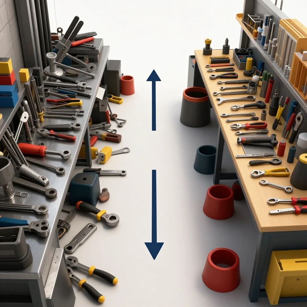
I remember a specific job involving a large baseplate for a custom hydraulic press. The fabricator was highly skilled, but the bolt holes were consistently 1/16 of an inch out of alignment. He was blaming the drill press and the bits. After I stepped in and performed a systematic check of his marking process, we found the culprit. He was using a thick carpenter’s pencil on oily steel. The width of the pencil lead alone was creating a variable he couldn’t control. By switching to a systematic layout method using scribes and layout fluid, we brought the tolerance back to within 0.005 inches.
Mastering the art of transferring dimensions to metal requires more than just a steady hand. It requires a diagnostic mindset. You have to treat every measurement as a potential point of failure. This guide breaks down how to identify these errors before they ruin your workpiece, focusing on the manual tools and techniques that form the backbone of precision fabrication.
Establishing a Systematic Diagnostic Framework for Layout
A diagnostic framework for layout is a repeatable sequence of checks used to ensure that dimensions are transferred from a drawing to a workpiece without error. It involves verifying tool accuracy, preparing the material surface, and using a single reference point for all measurements.
When I walk into a shop to solve a fitment issue, the first thing I look for is the “datum” or reference edge. A common mistake is measuring from one end of a plate for the first hole, then measuring from that hole to the next. This is called “stacking” or cumulative error. If your first measurement is off by 0.010 inches and your second is also off by 0.010, you are now 0.020 inches out of spec.
To fix this, I teach the use of a baseline. You pick one machined edge or a center line and pull every single measurement from that one spot. This keeps your errors isolated rather than additive. Building this habit is the first step in moving from “rough” work to precision fabrication.
- Select a primary datum edge that is straight and square.
- Use a single measuring tool for the entire layout to avoid calibration differences.
- Verify the drawing dimensions against the physical stock before marking.
Precision Marking and Surface Preparation Techniques
Surface preparation is the process of cleaning and coating metal to make layout lines highly visible and permanent during the fabrication process. Using layout fluids like Dykem Blue allows a scribe to cut through the dye, revealing a bright, thin line of bare metal.
I often see guys trying to mark on mill scale or rusted plate with a Sharpie. The problem is that a felt-tip marker creates a line that is roughly 0.030 to 0.050 inches wide. In the world of precision metalworking, that is a canyon. If you aim for the left side of the line and your colleague aims for the right, the part will never fit.
By applying a thin, even coat of layout fluid, you create a high-contrast surface. When you use a sharpened tungsten-carbide scribe, you are creating a line that is only 0.005 inches wide. This level of detail allows you to see exactly where the center of your punch should land. It also helps you spot errors early. If a line looks “thick,” it means your scribe is dull or your pressure was inconsistent.
| Tool Type | Line Width (Inches) | Best Use Case |
|---|---|---|
| Carpenter Pencil | 0.040 – 0.060 | Rough framing, non-critical cuts |
| Soapstone | 0.030 – 0.050 | Heat-resistant marking for welding |
| Fine-Tip Marker | 0.020 – 0.030 | General layout on clean metal |
| Steel Scribe | 0.005 – 0.010 | Precision layout on layout fluid |
Resolving Parallax and Visual Transfer Errors
Parallax error occurs when the observer’s eye is not positioned directly perpendicular to the measuring scale, causing the mark to appear shifted. Visual transfer errors happen when a dimension is incorrectly read from a rule and moved to the metal surface.
I once worked with a guy who was consistently “short” on his cuts. We spent an afternoon watching him work and realized he was looking at his ruler from a 45-degree angle. Because the ruler has thickness, looking at it from the side made the markings appear to be in a different spot on the metal.
To solve this, you must keep your line of sight directly over the mark. Better yet, use a “hook rule” or a combination square. These tools physically register against the edge of the material, removing the need to “eye” the starting point. When using a standard rule, I often “burn an inch.” This means I start my measurement at the 1-inch mark instead of the end of the rule. The end of a steel rule can get worn down over time, losing its accuracy. Starting at the 1-inch mark gives you a crisp, machined line to work from. Just don’t forget to subtract that inch from your final measurement.
- Align your eye directly over the graduation mark on the rule.
- Use a magnifying glass for high-tolerance work to ensure the scribe is centered.
- Place the rule on its edge so the graduations are in direct contact with the work surface.
Correcting Tool Calibration and Squareness Faults
Tool calibration is the process of verifying that your squares, rules, and dividers are accurate against a known standard. Squareness faults occur when a tool that is supposed to be at 90 degrees has been dropped or worn out of alignment.
You cannot trust a tool just because it is made of steel. I have seen brand-new combination squares that were out of square by 0.010 inches over a 6-inch span. To test a square, I use the “flip test.” Take a piece of scrap with one perfectly straight edge. Draw a line perpendicular to that edge. Flip the square over and draw another line right next to the first one. If the lines are not perfectly parallel, your square is a liar.
If you find a square is out of alignment, it is often due to a burr in the locking mechanism or a piece of grit in the channel. Cleaning the tool with a fine stone or a rag can often restore its accuracy. For dividers, ensure the points are sharp and equal in length. If one leg is shorter, the tool will “walk” as you try to scribe a circle, leading to an oval shape rather than a perfect radius.
- Check squares weekly using the flip test on a known straight edge.
- Inspect rule ends for rounded corners or “mushrooming” from drops.
- Verify divider tension to ensure the legs don’t move under pressure.
Troubleshooting Geometric Alignment and Right Angles
Geometric alignment involves using mathematical principles and specialized tools to ensure that two or more lines are perfectly perpendicular or parallel. This is critical for preventing “racked” frames where the structure is tilted or twisted.
When I’m building a large frame, I don’t just trust my square. I use the 3-4-5 rule, which is a practical application of the Pythagorean theorem. If one side is 3 feet and the other is 4 feet, the diagonal must be exactly 5 feet. If it is 5 feet and 1/8 of an inch, the corner is not square. This simple check has saved me hundreds of hours in rework.
Another common issue is “bowing” in long layout lines. If you are using a long straightedge, it can flex in the middle. I always verify long lines by checking the distance from the datum edge at three points: the start, the middle, and the end. If the middle measurement is different, your straightedge is either bent or shifting during the marking process.
| Geometric Check | Formula/Method | Tolerance Goal |
|---|---|---|
| Squareness | 3-4-5 Triangle | +/- 1/32″ over 5 feet |
| Parallelism | Constant Offset | +/- 0.005″ over 12 inches |
| Centering | Dividers/Trammel | +/- 0.002″ |
| Flatness | Straightedge/Feeler Gauge | < 0.003″ per foot |
Eliminating Cumulative Tolerance Stack-up
Tolerance stack-up is the total accumulated error resulting from a series of individual measurements. Eliminating this requires a shift from incremental measuring to absolute measuring, where every mark refers back to a single starting point.
In my early years, I watched a millwright struggle with a series of mounting brackets. He measured 4 inches for the first, then 4 inches from that mark for the second, and so on. By the time he reached the tenth bracket, he was nearly half an inch off. He was frustrated, blaming the tape measure. The tape was fine; his method was flawed.
The fix is to use a “layout string” of dimensions. If you need holes at 4, 8, 12, and 16 inches, you mark them all while the rule is held stationary at the zero point. You never move the rule until all marks are made. This ensures that even if you have a slight bias in how you read the marks, that bias is the same for every hole, and they remain correctly spaced relative to each other.
- Secure the workpiece to the bench so it cannot shift.
- Clamp your rule or tape measure to the datum edge.
- Mark all dimensions in one pass without moving the measuring tool.
Mastering the Use of Dividers and Trammel Points
Dividers and trammel points are tools used to scribe circles, arcs, and to step off equal distances along a line. They are essential for layout because they rely on physical geometry rather than reading a scale, which reduces human error.
I prefer dividers for layout because they are “fixed” once set. If I need to mark five holes exactly 2 inches apart, I set my dividers to 2 inches using a high-quality rule. I then “walk” the dividers down the line. The sharp points leave a tiny physical indentation in the metal. This is much more accurate than trying to place a pencil mark at every 2-inch graduation on a tape measure.
The biggest mistake with dividers is applying too much downward pressure. If you press too hard, the points can dig in and flex the legs outward, changing the dimension. Use a light touch and let the sharpness of the tool do the work. If you are working on a large scale, use trammel points on a rigid steel bar. This prevents the “spring” that occurs with large handheld dividers.
- Set dividers by placing one point in a rule graduation and the other at the desired length.
- Keep points needle-sharp using a fine oilstone.
- Lightly center-punch your starting point to give the divider leg a pivot home.
The Role of Layout Fluids and Scribing in Error Detection
Layout fluid is a translucent dye applied to metal to make scribed lines visible. Scribing is the act of scratching a line into the metal surface. Together, they provide a permanent record of the layout that won’t smudge or burn off.
I’ve seen many people skip the layout fluid because they are in a hurry. They end up squinting at a faint scratch on shiny steel, often misinterpreting which line is the “real” one after making a mistake. With Dykem Blue, if you make a mistake, you simply “paint it out” with a fresh dab of fluid and scribe the correct line. It provides a visual “undo” button.
When scribing, the angle of the tool is vital. You should lean the scribe away from the rule at a consistent angle. If you change the angle mid-stroke, the line will wander. I find that a 15-degree tilt works best. This keeps the point of the scribe tucked tightly against the bottom edge of the rule, ensuring the line is exactly where the rule says it should be.
- Clean the metal with degreaser before applying fluid.
- Apply a thin coat; thick coats can chip and obscure the line.
- Use a single, firm stroke for scribing to avoid “double lines.”
Diagnostic Tools and Calibration Checklist
To maintain high standards in layout, you need a set of tools that you know are accurate. A diagnostic specialist is only as good as his instruments. I keep a dedicated “layout kit” that stays in a protective case, away from the hammers and grinders that can knock things out of alignment.
Regularly checking your tools is not a waste of time; it is an investment in not wasting material. Every Monday morning, I spend ten minutes verifying my main square and my primary rule. I look for nicks in the edges and ensure the scribe points are sharp. If a tool fails the check, it gets repaired or replaced immediately.
- Combination Square: Check for 90-degree and 45-degree accuracy using the flip test.
- Steel Rule: Inspect the “zero” end for wear. Use a 0.005″ feeler gauge to check for gaps against a straightedge.
- Scribes: Ensure the tip is a sharp point, not a “hook.” Sharpen to a 20-degree included angle.
- Dividers: Check for leg play in the pivot joint. Tighten as needed.
- Surface Plate: If you have one, use it as your ultimate reference for flatness.
Common Layout Mistakes and How to Fix Them
Even with the best tools, mistakes happen. The key is to catch them before you start cutting. One of the most common errors is “reading the wrong side of the line.” If you are using a 1/8-inch thick saw blade, you must know if your layout line represents the left side, the right side, or the center of the cut.
If you find you’ve made a mistake, do not try to “adjust” it by eye. Clean the area, re-apply layout fluid, and start the measurement over from the datum. I have seen many people try to “split the difference” on a bad mark, only to end up with a part that is unusable. Precision is binary; it is either right or it is wrong.
Another issue is thermal expansion. If you layout a large aluminum plate in a 90-degree shop and then move it to a 60-degree assembly area, the dimensions will change. For most shop work, this is negligible, but for long spans (over 10 feet), it can be a factor. Always try to perform your layout and your cutting at the same ambient temperature.
- Mistake: Measuring from a rough-cut edge. Fix: Always grind or mill a true datum edge first.
- Mistake: Using a tape measure for small parts. Fix: Use a steel rule for anything under 12 inches.
- Mistake: Forgetting the “kerf” (width of the cut). Fix: Clearly mark which side of the line is the “waste” side.
Frequently Asked Questions
Why is my square giving me different readings on the same corner?
This is usually caused by “burrs” or debris on the workpiece or the tool itself. Even a tiny metal chip trapped between the square and the metal can throw the angle off by several degrees. Always wipe both surfaces clean with your hand before taking a measurement.
How often should I sharpen my scribe?
You should sharpen your scribe as soon as the line it produces starts to look “fuzzy” or wider than 0.010 inches. A sharp scribe should feel like it is “biting” into the metal with very little pressure.
Can I use a tape measure for precision layout?
Tape measures are designed for construction, not precision machining. The “hook” at the end is meant to move to account for its own thickness, but this mechanism can become bent or clogged with dirt. For any layout requiring tolerances tighter than 1/32 of an inch, use a solid steel rule.
What is the best way to mark a center point for drilling?
After scribing your intersecting lines, use a sharp “prick punch” (which has a 30-60 degree point) to mark the exact intersection. Follow this with a “center punch” (90-degree point) to create a larger divot for the drill bit to follow. This two-step process prevents the bit from “walking.”
How do I layout a circle if I don’t have a center point?
You can use a “center square” or a “hermaphrodite caliper” to find the center of round stock. Alternatively, scribe two chords across the circle and find their midpoints; the intersection of the perpendicular bisectors of those chords will be the center.
Why do my dimensions seem to change after I cut the metal?
This is often due to internal stresses being released in the metal during the cutting process, especially with cold-rolled steel. To minimize this, perform your rough cuts first, allow the metal to “settle,” and then do your final precision layout.
Is Dykem Blue the only layout fluid I can use?
No, there are many brands, and even a permanent marker can work in a pinch. However, professional layout fluids are designed to be thin and brittle so they don’t “smear” when the scribe passes through them, which is critical for accuracy.
How can I check for parallelism on a long plate without a large caliper?
Use a “surface gauge” or a combination square set to a specific length. Slide the base of the square along your datum edge and see if the end of the rule consistently touches your scribed line at multiple points along the length.
What should I do if my workpiece is too large for my rule?
Use a “trammel point” set on a long piece of square tubing or a specialized layout bar. This allows you to transfer large dimensions (several feet) with the same precision as a small pair of dividers.
Why does my scribe line look wavy?
This happens when you don’t apply consistent pressure or when the rule shifts. Clamp your straightedge to the work whenever possible. This allows you to use one hand to hold the rule and the other to focus entirely on the scribe’s path.
(This article was written by one of our staff writers, Paul Whitaker. Visit our Meet the Team page to learn more about the author and their expertise.)