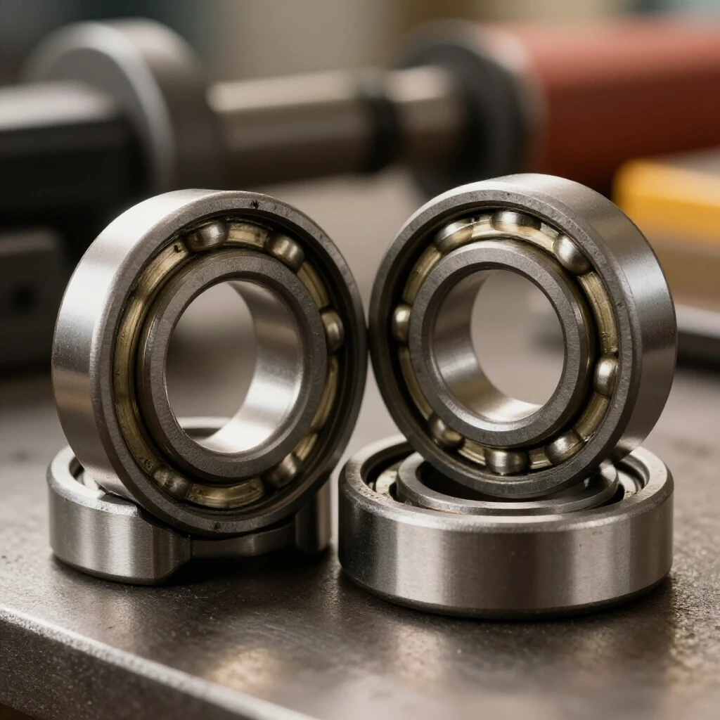
How to Check and Replace Worn Bandsaw Blade Guides (Fix)
In my eighteen years traversing the concrete floors of industrial fabrication mills, I have learned that the most frustrating failures are rarely the loudest ones. It is not the catastrophic motor blowout that keeps a shop lead awake at night; it is the subtle, creeping inaccuracy that turns a precision-cut steel beam into scrap. I remember a specific contract three years ago involving heavy-duty structural H-beams where we were losing nearly 0.040 inches of squareness over a twelve-inch cut. The operator was convinced it was a tensioning issue, but after an hour of systematic isolation, I found the culprit: a seized lower roller that had developed a flat spot thinner than a fingernail.
When your cuts start to wander or the machine begins to emit a high-pitched harmonic scream, your first instinct might be to blame the blade or the motor. However, in the world of precision metalworking, the support system—the components that keep the blade on its vertical and horizontal path—is usually where the diagnostic trail ends. Mastering the art of identifying and restoring these support elements is the difference between a shop that produces repeatable results and one that spends its weekends chasing “ghost” errors in their workflow.
Establishing a Systematic Diagnostic Framework for Blade Deviation
A diagnostic framework is a structured approach to problem-solving that moves from external symptoms to internal root causes. By isolating variables like lateral movement and thrust resistance, a fabricator can determine if a cut failure is due to mechanical wear or setup error. This prevents the common mistake of replacing expensive parts before confirming they are actually faulty.
When I approach a machine that is producing subpar results, I start with a clean slate. I don’t guess. I observe the machine under load and then under static conditions. The goal of a metalworking diagnostic guide is to eliminate the “maybe” and find the “is.” If the blade is twisting mid-cut, it is physically impossible for the guides to be doing their job correctly. I look for three specific indicators: heat discoloration on the blade sides, “chatter” marks on the cut face, and physical play in the guide assembly itself.
To begin, I perform a “static deflection test.” With the machine powered down and locked out, I apply moderate finger pressure to the side of the blade between the guide blocks. If I can see the blade move more than a few thousandths of an inch before it hits the support, the clearance is out of spec. This simple observation often reveals that the components have vibrated loose or have worn down to the point where they no longer provide a rigid path for the steel.
Identifying Signs of Lateral Support Failure
Lateral support failure occurs when the side guides—whether bearings, ceramic blocks, or steel inserts—no longer maintain a tight enough tolerance to prevent the blade from twisting. This leads to “bell-mouthed” cuts where the entry and exit points are straight, but the middle of the material is gouged. Identifying this early prevents tool chatter and preserves the integrity of the blade’s teeth.
In my experience, the side supports are the most common point of failure because they are constantly subjected to friction and fine metal dust. I look for “scoring,” which are deep grooves cut into the face of the guide. If you are using roller bearings, I check for “radial play”—the wiggle you feel when you push the bearing side-to-side. A healthy bearing should spin freely but have zero perceptible lateral movement.
| Symptom | Physical Observation | Likely Mechanical Root Cause |
|---|---|---|
| Concave/Convex Cut | Blade “bows” in the center of thick stock | Excessive clearance in side guides |
| High-Pitched Squeal | Metal-on-metal screeching during idle | Seized roller bearing or dry guide block |
| Blade “Walking” | Blade moves forward or backward on the wheels | Thrust bearing positioned too far back |
| Scoring on Blade Body | Deep horizontal lines on the smooth part of the blade | Guides are too tight or have embedded grit |
If I find that the guides are packed with “swarf”—the fine chips and oil from the cutting process—I know the issue might just be maintenance. However, if the surfaces are pitted or the rollers have flat spots, no amount of cleaning will fix the geometry. You cannot adjust your way out of a physical flat spot on a hardened steel roller.
Evaluating the Condition of Thrust Bearings and Rear Supports
The thrust bearing is the component located directly behind the back edge of the blade, responsible for absorbing the pressure as the tool is pushed into the workpiece. When this part wears out, the blade will push backward during a cut, changing the effective tooth geometry and causing the blade to pop off the wheels. Evaluating this requires checking for “grooving” on the bearing face.
I often see thrust bearings that have a deep “V” groove worn into them. This happens when the bearing is seized and the blade has been rubbing against a stationary surface. When this occurs, the blade is no longer supported; it is being ground down. To test this, I spin the thrust bearing by hand. It should feel smooth, like it’s floating on oil. If it feels “crunchy” or resists movement, the internal races are shot.
Another thing I look for is the “offset.” Most thrust bearings are designed so the blade does not hit the center of the bearing. If the blade is hitting the center, it won’t spin the bearing effectively, leading to localized heat. I check the alignment to ensure the blade hits the outer third of the bearing face. This creates the leverage needed to keep the bearing spinning during the cut, which drastically reduces friction-related heat.
The Process of Removing and Inspecting Worn Hardware
Removing the guide assembly is a methodical process that requires documenting the current position of all adjustment screws to ensure the machine can be returned to a baseline state. This stage involves disassembling the upper and lower guide blocks to inspect for hidden cracks or stripped threads. It is the only way to confirm the extent of the mechanical degradation.
I always start with the upper guides because they are easier to access, but I never ignore the lowers. The lower guides are often buried in a mountain of chips and coolant, making them the most neglected part of the machine. I use a set of Allen keys and a small brass brush to clear the area before I start loosening bolts.
- Lockout/Tagout: Never work on the guide system without physically disconnecting the power.
- Loosen Lateral Adjusters: Back off the side guides until they are no longer touching the blade.
- Remove the Guide Housing: Most modern saws use a single bolt or a dovetail mount to hold the guide assembly.
- Inspect the “Seat”: Look at where the guide sits against the arm. If there is galling or burrs on the mounting surface, the guide will never sit square, no matter how new the parts are.
- Check Thread Integrity: I often find that the adjustment screws have “crept” because the threads are stripped. If the screw feels loose in the hole, I’ll need to tap it for a larger size or use a thread insert.
Selecting Replacement Components: Bearings vs. Blocks
Choosing the right replacement material involves balancing the need for rigidity against the risk of heat buildup. Roller bearings offer the least friction but can fail in high-dust environments, while ceramic or carbide blocks provide superior blade dampening at the cost of increased heat. The choice depends on the material being cut and the required precision.
In high-production environments where we are cutting stainless steel or high-nickel alloys, I often lean toward high-quality ball bearings. They handle the high blade speeds better without generating the heat that can ruin the blade’s temper. However, if I’m working on a vertical saw doing intricate contour work, I prefer ceramic blocks. They support the blade closer to the teeth, which prevents the blade from “twisting” during tight radii.
When I buy replacement bearings, I don’t just look for the size; I look for the “ABEC rating.” For a standard workshop saw, an ABEC 3 or 5 is sufficient. Anything higher is overkill for a bandsaw, and anything lower might have too much internal play right out of the box. I also ensure the bearings are “shielded” (ZZ) or “sealed” (2RS) to keep the metal dust out of the grease.
Precision Installation and Clearance Calibration
Installation is the stage where the most errors occur, usually by setting the guides too tight or too far forward. Calibration requires using precise measuring tools, like feeler gauges, to set a gap that allows the blade to move freely while providing enough support to resist lateral deflection. This balance is the key to a long-lasting repair.
When I install new guides, I use a “dollar bill” or a 0.003-inch feeler gauge as my standard. I want the guides to be close enough that they almost touch the blade, but not so close that they pinch it. If you pinch the blade, you create a “heat sink” that will cause the blade to expand, get even tighter, and eventually snap or ruin the guides you just installed.
- Step 1: Position the blade on the wheels and tension it to the manufacturer’s spec.
- Step 2: Slide the guide assembly forward until the front edge of the guides is just behind the “gullet” (the bottom of the tooth valley). If the guides hit the teeth, they will be destroyed instantly.
- Step 3: Set the thrust bearing so it is about 0.010 to 0.015 inches behind the back of the blade when the machine is idling. It should only touch the blade when you are actually cutting.
- Step 4: Tighten the side guides against a 0.003-inch feeler gauge on both sides.
- Step 5: Rotate the wheels by hand to ensure the blade weld passes through the guides without bumping.
Case Study: Resolving a Chronic 0.010-Inch Drift
I once consulted for a shop that was struggling with a high-end horizontal saw. They were cutting 4-inch solid 4140 steel rounds, and every cut was drifting 0.010 inches to the left. They had replaced the blade three times and checked the wheel alignment twice. When I arrived, I performed a “sweep” of the guide arm.
By mounting a dial indicator to the guide arm and moving it across its travel, I realized the guide arm itself was not parallel to the bed. However, the root cause was the guides. The inner guide block had worn more than the outer one, creating a “wedge” shape. Even though the operator thought he was setting them square, the worn face was forcing the blade into a slight twist the moment it hit the metal.
We replaced the worn steel blocks with carbide-faced inserts and spent twenty minutes squaring the guide arm to the vise. The drift disappeared immediately. This taught the crew that “close enough” isn’t enough when the material is hard and the cut is deep. We recorded the new baseline measurements in their maintenance log to ensure they could spot the wear before it affected production again.
Mechanical Tolerances and Maintenance Benchmarks
Maintaining a machine requires knowing the specific metrics that define a “healthy” state. These benchmarks, derived from mechanical engineering standards, provide a clear pass/fail criteria for the operator during daily inspections. Ignoring these tolerances leads to a gradual decline in machine performance and increased tool costs.
In my shop, I keep a small chart taped to the side of every saw. It lists the “Allowable Play” for every major component. For guide bearings, I allow zero visible light between the bearing and the blade when adjusted, but the bearing must still spin freely. For the thrust bearing, the gap must be checked every Monday morning.
| Component | Metric/Measurement | Acceptable Tolerance |
|---|---|---|
| Side Guide Gap | Feeler Gauge | 0.002″ – 0.004″ |
| Thrust Bearing Gap | Feeler Gauge | 0.010″ – 0.020″ |
| Guide Arm Squareness | Machinist Square | < 0.002″ over 6″ |
| Bearing Radial Play | Dial Indicator | < 0.001″ |
If these numbers start to drift, I know it’s time for a teardown. Keeping a maintenance history planner helps me track how long a set of guides lasts under specific workloads. If I see that we are burning through bearings every two weeks, I know we either have an alignment issue or we are using the wrong type of support for the material.
Advanced Diagnostic Tools for Modern Fabricators
While the old-school methods of feel and sound are invaluable, modern diagnostic tools allow for a level of precision that was previously impossible. Digital dial indicators, infrared thermometers, and vibration spectrum analyzers can identify a failing bearing or a misaligned guide arm long before the human eye can see the resulting cut error.
I frequently use an infrared heat gun to check my guides after a five-minute run. If one side guide is reading 140°F while the other is at 90°F, I know the hot side is too tight or the blade is rubbing due to a twist. This “thermal mapping” is a non-destructive way to see into the mechanics of the machine while it’s working.
- Digital Dial Indicator: Used to check the “runout” of the thrust bearing and the squareness of the guide arm.
- Infrared Thermometer: Identifies friction points and seized bearings by spotting localized heat spikes.
- Smartphone Vibration App: While not as precise as industrial sensors, these can help identify harmonic frequencies that suggest a bearing is failing.
- Precision Ground Straightedge: Essential for ensuring the guide path is perfectly linear across the entire throat of the saw.
Avoiding Common Pitfalls During the Restoration Process
The most common mistake I see is “over-tightening.” There is a psychological urge to make everything as tight as possible to ensure accuracy, but in machinery, “tight” often leads to “friction,” and friction leads to “failure.” Another mistake is only replacing the upper guides. The lower guides do just as much work but are harder to see, so they are often left to rot.
I also see people trying to “re-face” worn guide blocks on a bench grinder. Unless you have a surface grinder and the skills to use it, you will never get that block face perfectly square again. A block that is off by even half a degree will force the blade to wander. It is always more cost-effective to replace the part than to try and “save” it with a hand-held grinder.
Lastly, don’t ignore the guide arm itself. If the arm that holds the guides is loose or vibrating, the best guides in the world won’t save your cut. I always check the “gib” adjustments on the guide arm to ensure it slides smoothly but has zero “wobble” when locked in place. This rigidity is the foundation upon which the guides do their work.
Final Steps: Testing and Verification
Once the new hardware is in place and calibrated, the final step is a “verification cut.” This is not just any cut; it’s a test of the machine’s ability to hold a line under pressure. I use a piece of 2-inch square bar stock, as it provides enough surface area to show any deviation in the cut path.
I check the cut with a machinist’s square on all four sides. If the square light shows a gap at the bottom of the cut, I know my thrust bearing is likely too far back or the blade tension is too low. If the gap is on the side, my lateral guides need another 0.001 inch of tightening. This iterative process—adjust, cut, measure—is how you achieve “toolroom” accuracy in a fabrication environment.
Once the machine is dialed in, I lock everything down with a drop of medium-strength thread locker on the non-adjusting bolts. This prevents the vibrations of the shop from undoing all my hard work. A machine that is properly maintained and calibrated doesn’t just work better; it’s quieter, safer, and much more satisfying to operate.
Frequently Asked Questions
How do I know if my guides are too tight?
If the blade becomes hot to the touch (above 120°F) after a short idle period, or if you see blue discoloration on the blade body, the guides are likely pinching the metal. You should be able to move the blade slightly with your fingers when the tension is off; if it’s locked solid, back off the adjusters.
Can I use sealed bearings in a coolant-heavy environment?
Yes, in fact, I recommend it. While “shielded” bearings (metal covers) are okay for dry cutting, “sealed” bearings (rubber covers) do a much better job of keeping liquid coolant and fine grit out of the internal ball races, which significantly extends their lifespan.
Why does my blade keep jumping off the wheels even with new guides?
New guides won’t fix a tracking issue. If the blade is jumping, it’s usually because the thrust bearing is pushed too far forward, or the wheels themselves are misaligned. The guides are there to support the blade during the cut, not to force it to stay on the wheels.
How often should I replace ceramic guide blocks?
Ceramic blocks are extremely durable, but they can chip if the blade weld is “proud” (too thick). Inspect them every 50 hours of cutting. If you see chips or deep grooves, it’s time to flip them to a fresh side or replace them entirely.
Is there a difference between “guide blocks” and “roller guides”?
Yes. Guide blocks (steel, carbide, or ceramic) use sliding friction and are better at dampening vibration, making them ideal for high-precision, slow-speed work. Roller guides use rolling friction, which generates less heat, making them better for high-speed production cutting.
What is the best way to clean lower guides without disassembly?
I use compressed air and a long-handled stiff nylon brush. Avoid using aggressive solvents that can wash the grease out of the bearings. Regular cleaning prevents the buildup of “sludge” that can seize the rollers and lead to flat spots.
My saw uses “coolant through the guides.” Does this change the gap setting?
No, the gap setting remains the same (0.003″). However, you must ensure the coolant passages are not clogged. If the coolant isn’t reaching the interface between the blade and the guide, the resulting heat will cause the guides to expand and seize against the blade.
Can I replace just the bearings, or do I need the whole assembly?
Usually, you can just replace the bearings. Most manufacturers use standard-sized bearings (like the 608 series used in skateboards). Check the numbers on the side of the bearing race; if they match, you can save a lot of money by just buying the bearings from a supply house.
Why is my thrust bearing spinning even when I’m not cutting?
The thrust bearing should have a small gap (0.010″ – 0.015″) behind the blade. If it’s spinning while the saw is idling, it means the blade is pushed too far back on the wheels or the bearing is adjusted too far forward. This causes unnecessary wear on both the bearing and the back of the blade.
Does the thickness of the blade affect the guide setup?
Absolutely. Every time you switch to a blade with a different “gauge” (thickness), you must recalibrate your side guides. A 0.035″ blade will be loose in a guide set for a 0.042″ blade, leading to the very drift and chatter you are trying to avoid.
(This article was written by one of our staff writers, Paul Whitaker. Visit our Meet the Team page to learn more about the author and their expertise.)