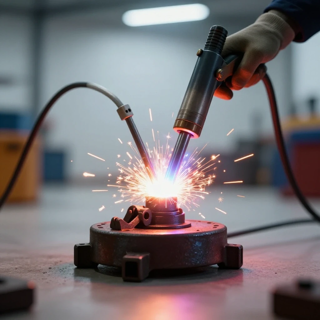
How to Build a Heavy Duty Rolling Engine Stand (DIY Plan)
I still remember the first time I built a structural frame for a shop project. I had measured everything three times and used a brand-new speed square. I felt confident as I laid down long, beautiful beads of weld. But when the metal finally cooled, the entire base had twisted nearly half an inch off the floor. It sat there rocking like a broken chair. That was my first real lesson in the physics of heat distortion and the importance of a structured build plan.
In my 13 years as a prototype technician, I have learned that building a reliable mobile support for heavy mechanical loads is not just about the welding. It is about the preparation. Whether you are building a utility trailer or a custom workshop fixture, the way you manage your material layout and weld sequencing determines if the final product is a tool or a hazard. This guide focuses on the technical reality of fabricating a heavy-duty rolling frame designed to hold 500 to 800 pounds of dead weight without buckling or warping.
Planning the Foundation with Accurate Material Layouts
Planning involves creating a detailed cut list and accounting for material loss during the cutting process to ensure the final frame dimensions remain within design tolerances. Without a plan, you are just making expensive scrap metal.
When I start a custom fabrication project, I begin with a “cut list.” This is a spreadsheet or a handwritten log of every single piece of steel required. You must account for the “kerf,” which is the width of the material removed by your saw blade. If you use a standard abrasive chop saw, your kerf might be 1/8 of an inch. If you use a cold saw or a bandsaw, it might be closer to 0.040 inches.
If you have ten cuts and ignore a 1/8-inch kerf, your final assembly will be over an inch short. I always mark my steel with a scribe or a fine-line silver pencil rather than a thick soapstone. A soapstone line can be 1/16 of an inch wide on its own. Accuracy in the layout phase is the only way to achieve tight dimensional tolerances of +/- 1/16th inch across a four-foot span.
Metal Kerf Allowances by Cutter Type
| Tool Type | Average Kerf Width | Accuracy Level | Best Use Case |
|---|---|---|---|
| Abrasive Chop Saw | 0.125″ (1/8″) | Low | Rough structural cuts |
| Portable Band Saw | 0.035″ – 0.042″ | High | Precise fit-ups |
| Cold Saw | 0.080″ – 0.100″ | Very High | Production-grade squareness |
| Plasma Cutter | 0.060″ – 0.150″ | Medium | Plate steel and gussets |
| Oxy-Acetylene | 0.125″ – 0.250″ | Low | Heavy plate teardown |
- Identify the total length of your main rails. For a standard automotive engine, a base of 36 to 48 inches is common.
- Calculate the width based on the center of gravity of the load. A 30-inch width usually provides enough leverage against tipping.
- Add 1/16th of an inch to every measurement as a “fit-up gap” to allow for weld penetration.
Selecting Structural Steel for High-Load Support Frames
Choosing the right wall thickness and shape, such as rectangular tubing, ensures the frame can handle 500 to 800-pound dynamic loads without bending or failing. Material selection is where most builders either overspend or create something flimsy.
For a heavy-duty mobile stand, I prefer 2.5-inch square tubing with a 3/16-inch (0.188″) wall thickness. While 1/8-inch tubing is easier to cut, it can flex under the weight of a fully dressed cast-iron V8 engine. Rectangular or square tubing offers much higher torsional rigidity than angle iron. Torsional rigidity is the ability of a material to resist twisting.
When you are moving a heavy load over an uneven shop floor, the frame experiences “dynamic loading.” This means the weight isn’t just sitting there; it is bouncing and shifting. A frame built from thin-walled material might hold the weight while stationary but could buckle when a caster hits a crack in the concrete. I always look for ASTM A500 Grade B structural steel for these projects because of its predictable yield strength.
Material Yield Strengths and Load Expectations
- Mild Steel (A36): Yield strength of approximately 36,000 psi. Good for general gussets and plates.
- Structural Tubing (A500): Yield strength of 46,000 psi. Ideal for the main chassis of the stand.
- Plate Steel (3/8″): Used for the mounting head where the load attaches. This needs to resist bending.
- Hardware (Grade 8): Always use high-strength bolts for the casters and the mounting interface.
Building Workshop Jigs to Maintain Squareness
Workshop jigs are temporary fixtures that hold metal pieces in precise alignment, preventing movement during the tacking and welding phases of construction. They act as a second set of hands that never gets tired or moves out of place.
You cannot trust your eyes to keep a project square. Even if you hold a piece perfectly while you tack it, the cooling weld will pull the metal toward the heat source. I use a “fixture table” approach, even if I am just working on a flat concrete floor. I bolt or clamp scrap pieces of angle iron to my work surface to create a “nest” for my project.
If you don’t have a dedicated welding table, you can build a temporary jig using heavy C-clamps and a known straight edge, like a piece of 4-inch I-beam or a thick aluminum extrusion. By locking the main rails into a jig, you force the metal to stay in place. However, you must remember that clamps alone cannot stop all warping. They simply minimize it until the structure gains enough strength to resist the pull.
Essential Tools for Layout and Fixturing
- Machinist Squares: These are more accurate than standard framing squares for checking 90-degree joints.
- Corner Clamps: Specialized clamps that hold two pieces of tubing at a perfect right angle.
- Leveling Feet or Shims: Used to ensure your work surface is flat before you begin.
- String Lines: A simple way to check for “bowing” across long spans of tubing.
Controlling Heat Distortion Through Strategic Weld Sequencing
Weld sequencing is the order in which you apply heat to a joint to balance the natural pulling forces of cooling metal, keeping the structure straight. This is the most critical part of preventing a “wobbly” stand.
When steel is heated to a molten state, it expands. As it cools and solidifies, it shrinks. This shrinkage is powerful enough to bend 1/4-inch steel plates. If you weld the entire top of a joint first, the cooling metal will pull the uprights inward. To combat this, I use a technique called “balanced welding.”
I start by placing small, strong tack welds at all four corners of a joint. A tack weld should be about 1/4 inch long and have good penetration. Once the entire frame is tacked and checked for squareness using the 3-4-5 triangle method, I begin the final welding. I never finish one joint completely before moving to the next. I weld two inches on the front-left, then move to the back-right. This distributes the heat evenly across the entire structure.
Weld Sequencing and Distortion Control
| Step | Action | Purpose | Result if Skipped |
|---|---|---|---|
| 1 | Four-point Tacking | Fixes geometry | Joint will “hinge” open |
| 2 | Diagonal Checking | Verifies squareness | Frame will be a trapezoid |
| 3 | Root Passes (Opposing Sides) | Balances initial pull | Significant angular distortion |
| 4 | Intermittent Beads | Manages heat soak | Metal loses structural temper |
| 5 | Final Cap Welds | Seals and strengthens | Weak joints under vibration |
Mounting Casters for Stability and Mobility
Proper caster placement involves positioning heavy-duty wheels to provide a wide footprint, ensuring the stand remains stable on uneven garage floors while under load. A stand that is hard to move or prone to tipping is a safety risk.
For a frame supporting 800 pounds, I do not use 2-inch plastic wheels. I select 4-inch or 5-inch polyurethane-on-iron casters. Polyurethane absorbs some of the floor vibrations, while the iron core prevents the wheel from flat-spotting under long-term loads. Each caster should be rated for at least 300 pounds to provide a safety margin.
The geometry of the caster mounting is also vital. I weld 3/8-inch thick steel plates to the corners of the base frame. These plates should extend slightly outward to widen the “stance” of the stand. When the casters can swivel 360 degrees, they need enough clearance so they don’t hit the frame or each other. I always use four-bolt mounting patterns rather than single-bolt stems, as the four-bolt design distributes the load across a larger surface area of the frame.
Caster Selection Metrics
- Load Rating: 1.5x the expected total weight divided by the number of wheels.
- Swivel Radius: Ensure the wheel can spin fully without hitting the frame.
- Braking Mechanism: At least two casters must have “total lock” brakes that stop both the wheel and the swivel.
- Mounting Plate Thickness: Minimum 5/16″ or 3/8″ to prevent “oil-canning” or flexing.
Case Study: The “T-Bone” Frame Failure
A few years ago, a colleague tried to build a support stand using a T-shaped base. He thought it would save material and make it easier to reach the load. However, he didn’t account for the “overhung load” center of gravity. When he mounted a heavy engine, the single leg of the “T” acted like a pivot point. The stand was incredibly unstable during movement.
I helped him redesign it into an “H-pattern” base. The H-pattern provides four points of contact with a wider center. We also added diagonal “kickers” or gussets at the main upright. These 45-degree braces are essential. They transform a 90-degree joint—which is susceptible to leverage—into a series of triangles. Triangles are the strongest shape in fabrication because they don’t allow the joints to rack or fold.
Actionable Framework for Frame Assembly
- Cut Phase: Mark all pieces using a scribe. Cut the longest pieces first to minimize waste.
- Deburring: Remove all dross and sharp edges. Clean the weld zones to bright metal (1 inch back from the cut).
- Layout: Place the main rails on a flat surface. Use blocks to ensure they are level.
- Initial Tacking: Place one tack on the top of each corner. Re-measure the diagonals.
- Squaring: If the diagonals are off by more than 1/8 inch, use a ratchet strap to pull the long diagonal into square before finishing the tacks.
- The “Star” Weld Sequence: Weld in a pattern similar to tightening lug nuts on a car wheel.
- Cooling: Allow the frame to air-cool. Never quench a structural weld with water, as this makes the steel brittle.
Correcting Heat Distortion After Welding
Sometimes, despite your best efforts, the metal still moves. This is the reality of working with heat. If a leg is lifting off the floor, you can use “flame straightening.” This involves heating the side of the tubing opposite the weld that caused the pull. As that heated spot cools, it shrinks and pulls the metal back toward center.
Another method is “mechanical persuasion.” I keep a heavy 10-pound sledgehammer and a few solid steel blocks in my shop. If a mounting plate is slightly tilted, a few controlled strikes can often bring it back within tolerance. However, this should be done sparingly. The goal is to build it straight the first time through proper sequencing.
Finalizing the Build with Reinforcements
Once the main frame is solid and square, I focus on the “high-stress” areas. For an engine stand, this is where the upright meets the base. I never rely on a single butt-weld here. I always add “fish plates” or “gussets.”
A fish plate is a piece of flat steel welded over the joint. It increases the surface area of the weld and provides a backup path for the load if the primary weld were to fail. I prefer triangular gussets cut from 1/4-inch plate. I weld them on both sides of the upright. This ensures that the stand can handle the “moment arm” or the leverage created by the heavy engine hanging off the front.
Checklist for Final Inspection
- Weld Quality: Check for porosity (small holes) or lack of fusion.
- Squareness: Measure diagonals one last time. Target: < 1/8″ difference.
- Caster Alignment: Ensure all four wheels touch the ground simultaneously.
- Hardware Tension: Use a torque wrench on caster bolts to ensure they won’t vibrate loose.
- Finish: Wipe the steel down with acetone and apply a coat of industrial primer to prevent rust.
Building a heavy-duty rolling support is a masterclass in garage fabrication. It requires you to think about physics, material properties, and the behavior of heat. By following a structured plan, using accurate layout tools, and respecting the power of weld shrinkage, you can create a piece of equipment that is safer and more reliable than anything you could buy off a shelf.
The most important step is the first one: slow down. Spend twice as much time with your square and scribe as you do with your welder. Your future self, trying to roll 800 pounds across a shop floor, will thank you for the extra effort.
Frequently Asked Questions
Why does my frame wobble even though I used a square? Wobble is usually caused by a work surface that isn’t perfectly flat or by welding one corner completely before tacking the others. The heat from the first weld pulls the frame out of alignment. Always tack the entire project on a leveled surface before doing final passes.
What is the best way to ensure the main upright stays at a perfect 90-degree angle? Use a large heavy-duty magnetic square or a dedicated corner jig. Additionally, weld the gussets simultaneously or in small increments on alternating sides to prevent the upright from “leaning” toward the side you are welding.
Can I use 1/8-inch wall tubing to save weight? For light loads under 300 pounds, 1/8-inch is fine. However, for 500 to 800-pound engines, the risk of “wall collapse” at the bolt holes or bending under dynamic loads is too high. Stick to 3/16-inch or 1/4-inch for structural safety.
How do I calculate the center of gravity for caster placement? The center of gravity (CG) for most engines is roughly in the middle of the block. Your casters should form a perimeter that is at least 20% wider than the load itself in all directions to prevent tipping during a sudden stop or when hitting a floor obstruction.
Should I MIG or TIG weld the frame? MIG is generally preferred for structural frames like this because it provides excellent penetration on thicker materials and is much faster. TIG is great for precision but can actually introduce more total heat into the part due to the slower travel speed, potentially causing more warping.
What size bolts should I use for the casters? Use Grade 8, 3/8-inch or 1/2-inch bolts with nyloc nuts. Standard Grade 5 hardware can shear under the high lateral forces of moving a heavy stand over a shop floor.
How do I stop the stand from “walking” when I am working on the engine? Ensure you use “Total Lock” casters. Standard brakes only stop the wheel from spinning. Total lock brakes stop the wheel and the swivel bearing, making the stand feel like a solid, stationary fixture.
Is it necessary to paint the stand? Yes. Raw steel begins to oxidize (rust) almost immediately from the humidity in the air. A simple coat of engine primer and implement paint will protect your hard work and make it easier to keep clean.
How much gap should I leave between my joints? A “root gap” of about 1/16 of an inch is ideal for MIG welding 3/16-inch tubing. This allows the weld puddle to penetrate all the way through the wall thickness, creating a much stronger bond than a surface-level weld.
What if I don’t have a flat floor to build on? You can create a “level plane” by using three points of contact (which always form a flat plane) or by using adjustable jack stands to level your main rails before you begin tacking. Never build a frame directly on a sloped or cracked driveway without shimming it level first.
(This article was written by one of our staff writers, Robert Kline. Visit our Meet the Team page to learn more about the author and their expertise.)