How to Build Strong Steel Ramps for Utility Trailers (Tips)
I have spent a decade and a half in fabrication shops, and if there is one thing I have learned, it is that steel has a mind of its own. I remember my first set of heavy-duty loading structures. I had measured everything to the sixteenth of an inch and spent hours on my cut list. But as soon as I started laying long beads down the side rails, the metal began to move. By the time I finished, the frames looked more like rocking chair runners than flat, stable platforms. That project taught me that custom fabrication projects are not just about sticking metal together; they are about managing heat and forces.
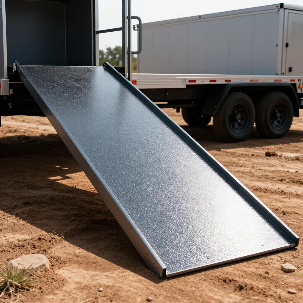
When you are building heavy-duty components for a utility trailer, the stakes are high. These structures need to be rigid enough to handle concentrated loads without buckling, yet straight enough to sit flush against the ground and the trailer deck. In this guide, I will break down the process of designing and fabricating robust steel ramps, focusing on the layout strategies and weld sequences that keep your work square and true.
Designing the Structural Frame and Load Distribution
Designing a structural frame involves calculating the span, the expected weight capacity, and the geometry needed to prevent bending under load. This stage determines the spacing of cross-members and the overall thickness of the steel to ensure the final product can safely support heavy equipment without permanent deformation.
Before you strike an arc, you need a plan that accounts for the physics of the load. Most utility ramps follow a “ladder” design, consisting of two main side rails connected by horizontal rungs. The side rails act as beams, and their vertical depth is the most critical factor in preventing deflection. If you use 2-inch angle iron, it will flex significantly more than 3-inch angle iron of the same thickness.
Calculating Span and Deflection
Deflection is the degree to which a structural element displaces under a load. In my shop, I aim for a maximum deflection of less than 1/4 inch over a 5-foot span when fully loaded. To achieve this, you must consider the “moment of inertia” of your chosen profile. A vertical piece of flat bar is much harder to bend than a horizontal one. This is why we almost always position the longest leg of our steel profile vertically.
Determining Rung Spacing
Rung spacing is about more than just traction; it is about supporting the tires or tracks of the equipment. For most utility applications, I recommend a spacing of 8 to 12 inches between rungs. If the gaps are too wide, the side rails take on more stress at specific points, increasing the risk of a localized failure or a “kink” in the rail.
- Heavy Equipment (Tractors/Skid Steers): 8-inch spacing.
- Light Equipment (ATVs/Mowers): 10 to 12-inch spacing.
- Point Load Reinforcement: Use 1/4-inch plate gussets at the junction of the ramp and the trailer attachment point.
Selecting Steel Grades and Material Profiles
Choosing the right material requires balancing weight, cost, and structural integrity using standardized steel grades. For most DIY builds, ASTM A36 mild steel is the industry standard due to its predictable yield strength and excellent weldability in a home shop environment.
For these types of builds, I typically stick to 1/4-inch thick material. While 3/16-inch can work for lighter loads, 1/4-inch provides a much larger margin for error, especially when considering the heat-affected zone (HAZ) created during welding. The HAZ is the area of metal that hasn’t melted but has had its properties changed by the heat, often becoming more brittle or prone to stress.
Angle Iron vs. Square Tubing
Angle iron is the traditional choice because it is easy to clean, paint, and weld. It also provides a natural “pocket” for the rungs to sit in. However, square tubing offers superior torsional rigidity (resistance to twisting). If you are worried about the ramp twisting under an uneven load, square tubing is the better choice, though it requires more complex miters or end caps to prevent internal corrosion.
| Material Profile | Dimensions (Inches) | Best Use Case |
|---|---|---|
| A36 Angle Iron | 2.5 x 2.5 x 1/4 | General utility, easy fabrication |
| A36 Square Tube | 2 x 2 x 3/16 | High-torque loads, twist resistance |
| A36 Channel | 3 x 1.5 x 3/16 | Extreme heavy-duty, industrial use |
| Flat Bar (Rungs) | 2 x 1/4 | Traction rungs for light/medium loads |
Precision Cutting and Kerf Allowances
Accurate square cuts are the foundation of a project that stays straight during assembly. This process involves accounting for the “kerf,” which is the width of the material removed by the cutting tool, to ensure that the final dimensions match the blueprint exactly.
One of the most common mistakes I see in workshop logs is neglecting the kerf. If you are using a chop saw with a 1/8-inch thick abrasive blade, every cut removes 1/8-inch of metal. If you have ten rungs to cut and you don’t account for that, your final rung will be over an inch short. I always mark my lines and then cut on the “waste side” of the line.
Calculating Kerf for Different Tools
Different tools have different kerf values. A bandsaw is much more precise and wastes less material than a plasma cutter or an abrasive chop saw. When I plan my cut list, I use the following benchmarks:
- Abrasive Chop Saw: 0.125 (1/8) inch
- Cold Saw: 0.090 to 0.120 inch
- Portable Band Saw: 0.025 to 0.035 inch
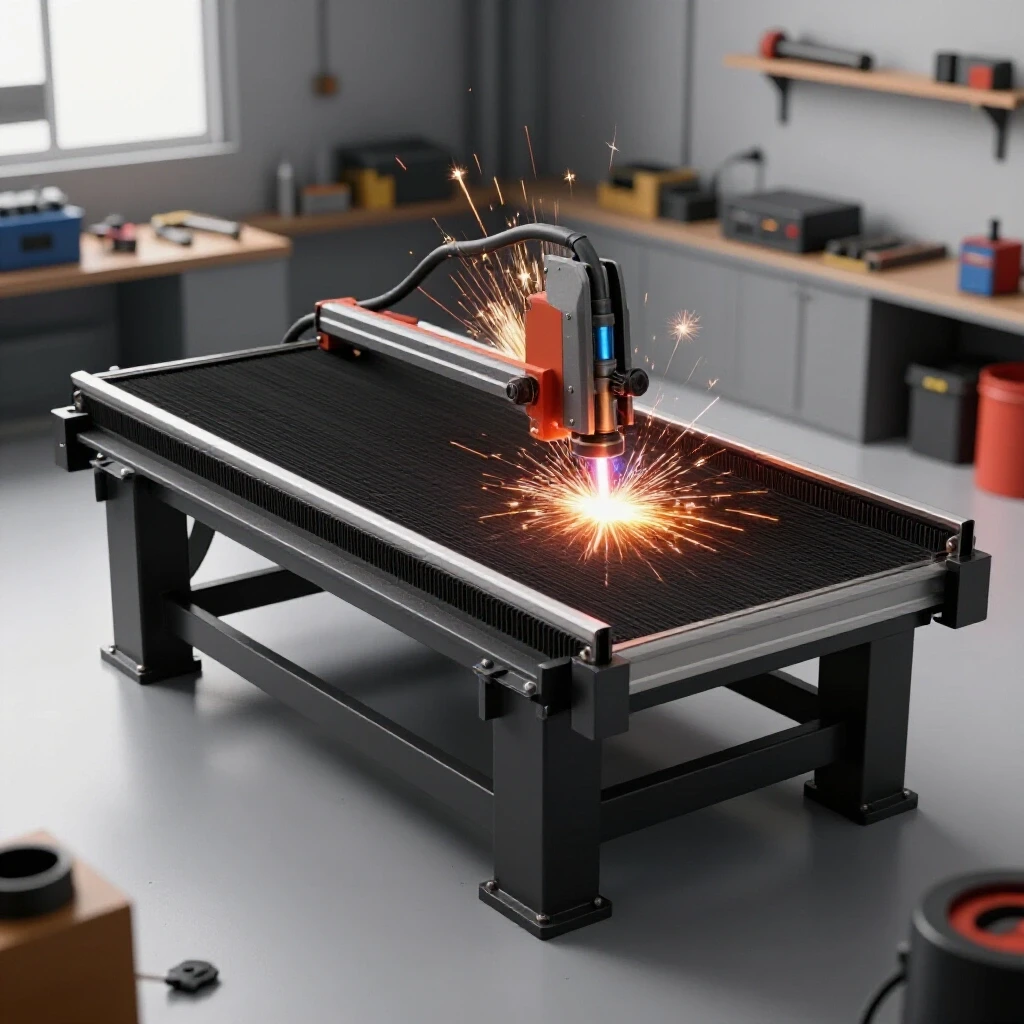
- Plasma Cutter (Handheld): 0.040 to 0.060 inch
Squaring the Stock
Before you start cutting your main rails, check the ends of the raw stock from the steel yard. They are rarely square. I always trim at least 1/2 inch off the end of a new 20-foot stick to establish a true 90-degree reference point. Use a high-quality machinist square to verify your saw’s fence before making critical cuts. Even a 1-degree error at the saw will result in a significant gap at the end of a 6-foot ramp.
Workshop Jigs and Fixtures for Alignment
Workshop jigs and fixtures are temporary structures used to hold workpieces in the exact position required for welding. They act as a physical constraint to prevent parts from shifting during the tack-welding phase and help maintain tight dimensional tolerances across multiple identical parts.
If you want two ramps that look and perform identically, you cannot build them “freehand” on a pair of sawhorses. You need a jig. A jig doesn’t have to be a fancy cast-iron welding table. I often build a temporary fixture right on my shop floor using scrap angle iron tacked down to a steel plate or even a heavy wooden workbench with stop blocks.
Building a Simple Ladder Jig
A good jig should clamp the side rails at the exact width required and provide a “stop” for the rungs. This ensures that every rung is perfectly perpendicular to the rails. I use C-clamps or F-clamps every 12 inches to pull the material tight against the fixture.
- Reference Line: Snap a chalk line or use a laser level to establish a perfectly straight reference for the side rails.
- Stop Blocks: Weld or bolt small blocks of steel at the start and end points of your frame.
- Squareness Check: Use the 3-4-5 triangle method to verify that your jig is square. Measure 3 feet on one side, 4 feet on the other, and the diagonal must be exactly 5 feet. For smaller ramps, use 18, 24, and 30 inches.
Using Modern Layout Tools
In my current setup, I use a digital angle finder and a laser square. These tools allow me to check for “twist” across the length of the frame. If one rail is 1/16-inch higher than the other at the far end, the ramp will wobble. I aim for a dimensional tolerance of +/- 1/16th inch over the entire length of the build.
Structural Tacking Strategies
Tack welding involves making small, temporary welds to hold the assembly together before the final beads are laid. Proper tacking requires specific spacing and sizing to resist the initial thermal expansion of the metal without cracking under the stress of the full weld.
Tacks are more than just “placeholders.” They are structural anchors that fight against the metal’s desire to warp. When I tack a ladder-style frame, I don’t just put one small dot of weld. I use “bridge tacks” that are about 1/2-inch long.
Tack Placement and Spacing
For a 1/4-inch thick steel frame, I place tacks on all four sides of every joint. If you only tack the top, the heat from the final weld will pull the bottom of the joint open, creating a “V” gap and bowing the rail.
- Tack the four corners of the main frame first.
- Re-verify the diagonals (they should be within 1/16th of an inch).
- Tack each rung in a “staggered” pattern. Do not tack all the rungs on the left side and then all the rungs on the right.
- Alternate: Tack Rung 1 Left, Rung 5 Right, Rung 3 Left, etc. This distributes the heat evenly.
Tack Size Benchmarks
- Material Thickness < 1/8″: 1/8″ diameter tack.
- Material Thickness 1/4″: 1/4″ to 3/8″ long tack.
- Tack Spacing: Every 4-6 inches for long seams, or at every corner for joints.
Weld Sequencing to Control Heat Warp
Weld sequencing is the strategic order in which welds are applied to a structure to balance the internal stresses caused by heating and cooling. By alternating the location of weld passes, a fabricator can use the shrinkage of one weld to counteract the pull of another.
This is where most custom fabrication projects go wrong. When steel is heated to a molten state, it expands. As it cools, it contracts. The cooling weld bead acts like a powerful winch, pulling the two pieces of metal toward the center of the weld. This is called “angular distortion.”
The “Back-Stepping” Technique
Instead of running one continuous 6-foot bead, I use back-stepping. This involves welding in short segments (about 2-3 inches) in the opposite direction of the overall progress. For example, if I am welding a side rail, I start 3 inches from the end and weld toward the end. Then I move back another 3 inches and weld toward the start of the first bead.
Alternating Sides and Planes
To keep a ramp straight, you must balance the “pull.” If you weld the top of the rungs, the ramp will bow upward. To counter this, you must weld the bottom or the sides of the rungs immediately after.
| Sequence Step | Location | Purpose |
|---|---|---|
| 1 | Top corners of rungs 1, 5, 10 | Initial structural anchor |
| 2 | Bottom corners of rungs 1, 5, 10 | Counter-pull to keep rails vertical |
| 3 | Side seams of middle rungs | Distribute heat to the center |
| 4 | Final perimeter beads | Seal the structure and add final strength |
Managing the Heat-Affected Zone (HAZ)
If the steel starts to glow dull red far away from your weld, you are putting too much heat into the part. I often keep a “heat sink”—a large block of aluminum or copper—clamped near my weld zone to soak up excess thermal energy. If you don’t have a heat sink, simply stop and let the metal cool until you can touch it with a gloved hand before moving to the next section.
Reinforcement Strategies and Gusseting
Reinforcement involves adding secondary structural components, like gussets or cross-bracing, to distribute loads and stiffen joints. These additions are critical at high-stress points where the ramp meets the trailer or where the most significant bending forces occur.
A ramp is only as strong as its weakest joint. Most failures occur at the “neck”—the point where the ramp hooks onto the utility trailer. This area experiences high shear forces. I always reinforce this transition with 1/4-inch triangular gussets.
Adding Gussets for Torsional Strength
Gussets prevent the “parallelogram” effect, where a square frame tries to lean into a diamond shape. By welding a small triangular plate into the corners of the main frame, you significantly increase the rigidity of the assembly.
- Gusset Size: For a 3-inch rail, use a 3×3-inch triangle.
- Welding Gussets: Do not weld all the way into the very tip of the corner. Stop your weld about 1/4-inch short to avoid creating a “stress riser” that could lead to a crack.
Cross-Bracing for Stability
If your ramps are wider than 16 inches, consider adding a diagonal cross-brace between two of the rungs. This prevents the side rails from “walking” or moving independently of each other under a shifting load. Even a 1-inch flat bar welded diagonally across the underside of the rungs can make a massive difference in how solid the structure feels.
Post-Weld Straightening and Correction
Post-weld straightening is the process of correcting any remaining distortion using controlled heat, mechanical force, or strategic weld beads. Despite the best sequencing, some movement is inevitable, and these techniques help return the project to its intended dimensions.
Even with perfect sequencing, you might end up with a slight bow. Don’t panic. This is a normal part of working with steel. Professional fabricators use “flame straightening” or “mechanical quenching” to bring parts back into alignment.
Using Heat to Straighten
If a rail is bowed upward, you can apply heat to the “long” side (the side that needs to shrink). Use an oxy-acetylene torch to heat a small, cherry-red spot on the outside of the bow. As the spot cools, it will shrink more than the surrounding metal, pulling the rail straight. I recommend doing this in very small increments.
Mechanical Straightening
For minor tweaks, I use a heavy-duty hydraulic press or even a simple bottle jack and a stout chain. By anchoring the ends of the ramp and applying pressure to the high point of the bow, you can “cold-set” the steel back into position. Be careful not to exceed the yield strength of the material, or you could cause a permanent kink.
- Identify the highest point of the warp.
- Secure the ends of the ramp to a rigid surface (like a trailer frame or a heavy workbench).
- Apply gradual pressure to the warp using a jack.
- Check for straightness frequently; it often takes less pressure than you think.
Build Log: Heavy-Duty 5-Foot Utility Ramps
To give you a realistic idea of what this takes, here is a breakdown of a recent build I completed for a local landscaper. These were designed to handle a 5,000-lb compact tractor.
Material List and Cost Tracking
- Side Rails: 20ft of 3″ x 3″ x 1/4″ A36 Angle Iron ($140)
- Rungs: 20ft of 2″ x 2″ x 1/4″ A36 Angle Iron ($90)
- Gussets/Plate: 2 sq. ft. of 1/4″ Plate ($30)
- Consumables: 2 lbs of E7018 Welding Rods, 2 Grinding Discs ($25)
- Total Material Cost: $285
- Total Time: 6.5 Hours
Fabrication Steps
- Cutting: I spent the first 90 minutes cutting the rails to 60 inches and the 12 rungs to 14 inches. I used a bandsaw to ensure 0.030-inch kerf accuracy.
- Layout: I clamped the side rails to my welding table, using a spacer block to maintain a 14-inch internal width.
- Tacking: I spent 45 minutes tacking every rung. I checked the diagonals after every four rungs to ensure the frame stayed square.
- Welding: I used a back-stepping sequence, welding the vertical faces first, then flipping the ramps to weld the horizontal flats. I allowed 15 minutes of cooling time between major passes.
- Finishing: I ground down any sharp burrs and added the top “hook” plates using 3/8-inch thick flat bar for extra security.
Common Pitfalls and How to Avoid Them
Even experienced builders run into issues. The key is recognizing them before they become permanent fixtures of your project.
- Over-Welding: It is tempting to put a massive bead on every joint. More weld does not always mean more strength; it often just means more heat and more warping. A 3/16-inch fillet weld is usually sufficient for 1/4-inch material.
- Ignoring the Floor: If your shop floor isn’t flat, your ramps won’t be flat. I always use a 4-foot level to check my work surface before I start my layout.
- Poor Grounding: A bad ground clamp connection can cause arc blow and inconsistent penetration. Always grind a clean spot on your workpiece for the ground clamp as close to the weld area as possible.
Final Inspection and Quality Benchmarks
Before you put these into service, you need to verify their structural integrity. I perform a simple “bounce test” and a visual inspection of every weld.
- Weld Consistency: Look for uniform ripples and a lack of undercut (where the weld eats into the base metal).
- Alignment Check: Lay both ramps side-by-side on a flat floor. They should be identical. If one “rocks,” it has a twist that needs to be corrected.
- Load Testing: Place the ramps on the trailer and drive the equipment halfway up. Stop and check for any signs of popping welds or excessive flexing.
Building your own utility components is a rewarding way to improve your fabrication skills. By focusing on the fundamentals of layout, heat management, and structural design, you can create a set of ramps that are safer and more durable than anything you could buy off a shelf.
FAQ
What is the best steel thickness for ramps carrying a 3,000-lb mower?
For a 3,000-lb load, I recommend 3/16-inch thick A36 angle iron for the side rails and 1/8-inch or 3/16-inch for the rungs. If the span is longer than 5 feet, I would jump up to 1/4-inch for the side rails to prevent excessive “spring” or bouncing when loading.
How do I prevent the side rails from bowing inward during welding?
The rails bow inward because the welds on the rungs shrink as they cool. To prevent this, use a “spreader bar”—a piece of scrap wood or steel cut to the exact internal width—and wedge it between the rails near the joint you are welding. Keep the spreader in place until the weld is cool to the touch.
Should I use MIG or Stick welding for this project?
Both work well, but they have different advantages. MIG is faster and produces less slag, making it easier for complex metal layout tips and tight corners. Stick (SMAW) with an E7018 rod provides deeper penetration on thicker 1/4-inch steel and is more forgiving if you are working outdoors or with steel that has some mill scale.
How much gap should I leave between the rung and the side rail?
Ideally, you want a “press fit” or a gap of no more than 1/16-inch. If the gap is too large, the weld will have to bridge a wide space, which increases the amount of heat needed and significantly increases the risk of warping.
Can I use 2×4 steel tubing instead of angle iron?
Yes, 2×4 tubing (placed vertically) is incredibly strong. However, it is heavier and more expensive. If you use tubing, make sure to seal the ends completely with weld-on caps to prevent water from sitting inside and rusting the structure from the inside out.
Why do my welds crack after the first few uses?
Cracked welds are usually a sign of “cold lap” (lack of fusion) or brittle welds caused by cooling the steel too quickly with water. It can also happen if the rungs are not properly gusseted, causing the weld joints to take all the torsional stress. Ensure you have good penetration and let the metal cool naturally in still air.
How do I calculate the correct angle for the ramp “feet”?
The angle depends on the height of your trailer deck. I usually set the ramps against the trailer at the desired slope, then use a sliding T-bevel or a digital angle finder to mark the cut line where the ramp meets the ground. This ensures the “foot” sits flat, distributing the weight over a larger surface area.
Is it necessary to paint the steel immediately?
Steel begins to oxidize (rust) almost immediately, especially in humid environments. Once you finish your final straightening and cleaning, wipe the metal down with a degreaser and apply a high-quality zinc-rich primer. This protects your metal warping solutions and structural work for years to come.
How do I handle “arc blow” when welding in tight corners?
Arc blow happens when magnetic fields deflect your welding arc. It is common in the corners of angle iron. To fix this, try switching to AC (if using stick), move your ground clamp to a different location, or reduce your arc length (hold a “tighter” arc).
What is the 3-4-5 rule in metal fabrication?
The 3-4-5 rule is a way to ensure a corner is exactly 90 degrees. Measure 3 inches (or feet) from the corner along one rail and 4 inches along the other. If the diagonal distance between those two points is exactly 5 inches, your corner is perfectly square. This is essential for accurate square cuts and frame alignment.
(This article was written by one of our staff writers, Robert Kline. Visit our Meet the Team page to learn more about the author and their expertise.)