How to Build a Heavy Steel Anvil Stand to Absorb Noise (Fix)
I remember the first time I set up a shop in a residential neighborhood. I had just finished a custom utility trailer frame and decided to celebrate by doing some light forging on a scrap-rail anvil. The first blow of the hammer didn’t just shape the metal; it sent a piercing, high-pitched ring through the walls of my garage and, as I later learned, directly into my neighbor’s living room. That “ping” is the sound of wasted energy and poor vibration control.
In my 13 years as a prototype technician and fabricator, I have learned that a tool is only as good as the foundation it sits on. When you are swinging a four-pound rounding hammer, you want that energy going into the workpiece, not into the floor or the air as noise. Building a high-mass support structure requires more than just sticking some metal together. It demands a deep understanding of metal behavior, weld sequencing, and material physics to ensure the final product stays flat, square, and silent.

Designing the Foundation: Material Selection and Cutting Lists
This phase involves choosing the right steel profiles and calculating exact dimensions while accounting for the material lost during the cutting process.
Before you strike an arc, you need a plan that respects the physical reality of steel. For a project intended to dampen vibration, mass is your best friend. I prefer using thick-wall square tubing, typically 3/16-inch or 1/4-inch wall thickness, or heavy plate. The goal is to create a cavity that can be filled with a dampening medium later.
When I layout my cutting list, I always account for the kerf, which is the width of the material removed by the saw blade. If you ignore kerf, a frame designed to be exactly 24 inches wide will end up 23-7/8 inches wide after four cuts with an abrasive saw. This leads to gaps that require more filler wire and create more heat, which inevitably leads to warping.
- Abrasive Chop Saw Kerf: 1/8 inch to 5/32 inch.
- Cold Saw/Bandsaw Kerf: 1/16 inch.
- Plasma Cutter Kerf: 1/16 inch to 1/8 inch (depending on tip size).
I use a simple tracking log for my material. I list the required finished length, the calculated kerf for my specific saw, and the total raw stock needed. This prevents the “short-stick” surprise halfway through the build.
Why Accurate Square Cuts Matter for Vibration Control
Precision cutting is the process of ensuring every mating surface is perfectly perpendicular or at the correct angle to prevent uneven weight distribution.
If your cuts aren’t square, your joints won’t close properly. In a high-impact tool base, a gap in a joint acts like a spring. It allows the structure to flex and vibrate, which is exactly what we are trying to avoid. During my time building custom chassis, I saw how a 1-degree error at a joint could result in a 1/2-inch deviation over a four-foot span.
To ensure your cuts are dead-on, check your saw’s fence with a machinist’s square before every major project. Don’t trust the built-in scales on most hobbyist chop saws; they are often stamped into the metal and can be off by several degrees. I use a digital angle finder to verify the blade-to-table relationship.
- Tolerance Goal: +/- 1/32 inch on length.
- Angular Tolerance: Within 0.5 degrees of the target angle.
Building Workshop Jigs to Control Alignment
Workshop jigs are temporary structures or fixtures used to hold workpieces in a fixed position during the assembly and welding process.
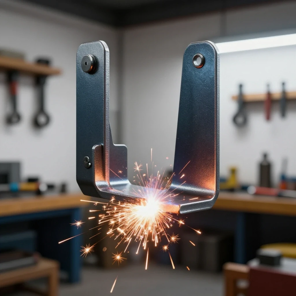
One of the biggest mistakes I see in home shops is “freehand” welding. Steel is a dynamic material; as it heats up, it expands, and as it cools, it contracts. If you don’t restrain the metal, the cooling weld will pull your perfectly square legs into a trapezoid. I always build a simple fixture on my welding table using scrap angle iron or heavy-duty magnets.
For a heavy base, I layout the perimeter on a flat surface and use “cleats”—small blocks of steel tacked to the table—to trap the workpieces. This prevents the base from “walking” as I apply heat. If you don’t have a dedicated welding table, a thick piece of plywood can work as a layout template, but you must be careful with fire and use metal spacers.
Structural Tacking Strategies for Heavy Assemblies
Tack welding involves placing small, temporary beads at key points to hold the assembly together while checking for squareness before the final beads are laid.
A tack weld needs to be strong enough to resist the cooling forces of the metal but small enough to be easily ground away if you need to make an adjustment. For 1/4-inch wall tubing, I usually place 1/2-inch long tacks at every corner. I never weld all four sides of a joint at once. Instead, I tack the “outside” corners first, check for square using a framing square or by measuring diagonals, and then tack the “inside” corners.
- Diagonal Measurement Rule: If the distance from the top-left corner to the bottom-right corner is exactly the same as top-right to bottom-left, your frame is square.
- Tack Spacing: For long seams, place a tack every 3 to 4 inches to prevent the plates from “zippering” or bowing out.
Why Weld Shrinkage Warps Square Structures
Weld shrinkage is the physical contraction of the weld metal and the surrounding heat-affected zone as it cools from a molten state to room temperature.
When you lay a bead, the molten steel is at its maximum volume. As it solidifies and cools, it shrinks. This shrinkage exerts thousands of pounds of force on your joint. If you weld only one side of a leg, that leg will bow toward the weld. This is called “angular distortion.”
In my years of custom fabrication projects, I’ve found that the best way to fight this isn’t through brute force, but through sequence. You have to anticipate the pull. If I know a weld is going to pull a leg 1/16 of an inch “inward,” I might actually set the leg 1/16 of an inch “outward” before welding. This is called pre-setting, and it’s a pro move that saves hours of straightening later.
| Weld Type | Typical Shrinkage Rate | Mitigation Strategy |
|---|---|---|
| Fillet Weld (T-Joint) | 1/16″ to 1/8″ pull | Weld in short segments, alternate sides |
| Butt Weld (Flat) | 1/32″ longitudinal | Use tacks and back-stepping |
| Corner Weld | Significant angular pull | Pre-set the angle slightly open (91 degrees) |
Executing Weld Sequences to Minimize Distortion
Weld sequencing is the planned order of applying beads to balance the heat input and the resulting stresses across the entire structure.
To keep a heavy base flat and true, you cannot simply start at one corner and go all the way around. I use a “staggered” approach. I might weld the front-left joint, then move to the back-right joint. This distributes the heat across the mass of the steel, preventing one area from becoming a “heat sink” that pulls the rest of the project out of alignment.
I also utilize the back-step welding technique. Instead of welding from left to right in one long bead, I break the seam into three-inch segments. I start three inches in from the edge and weld toward the edge. Then, I move six inches in and weld back toward the start of the first bead. This significantly reduces the cumulative stress on the metal.
- Tack all joints and verify diagonals.
- Weld the “inside” corners of the base frame first.
- Move to the opposite corner to balance the heat.
- Weld the vertical supports using the back-step method.
- Allow the metal to air cool—never quench it with water, as this can cause brittleness and extreme warping.
Implementing Vibration Dampening and Noise Reduction
Noise reduction in steel structures is achieved by increasing the mass and introducing materials that absorb or break up sound waves.
A hollow steel stand is basically a giant bell. To “fix” the noise issue, we need to change its resonant frequency. The most effective method I’ve used involves filling the central columns with dry masonry sand. The sand particles rub against each other when the stand is struck, converting the vibrational energy into a tiny amount of heat instead of sound.
Before you weld the top plate onto your stand, fill the legs or the central cavity with sand. Make sure the sand is bone-dry; any moisture trapped inside will turn to steam when you weld the top plate on, which can be dangerous. I often leave a small “vent hole” (about 1/8 inch) in a non-structural area to allow any expanding air or moisture to escape during the final welding process.
- Mass Calculation: Filling a 6x6x24 inch column with sand adds roughly 45-50 pounds of dead weight.
- Silicone Bedding: Applying a thick bead of 100% silicone caulk between the anvil and the steel top plate creates a “gasket” that prevents metal-on-metal vibration.
Correcting Heat Distortion and Final Leveling
Final leveling is the process of checking the completed structure for any warping caused by welding and using mechanical means to ensure it sits flat on the floor.
Even with perfect sequencing, you might find a slight “rock” in your stand once it’s finished. Metal is stubborn. If the base plate has warped slightly, I use a large angle grinder with a 40-grit flap disc to take down the high spots.
If the distortion is more severe, you can use “flame straightening.” By applying heat to the side opposite of the warp and then letting it cool, you can pull the metal back into position. However, this is an advanced technique. For most workshop fixtures, a bit of strategic grinding or adding shim feet is a more practical solution.
Practical Benchmarks for a High-Quality Build
When you are deep in the fabrication process, it’s easy to lose track of the details. I keep a checklist on my shop wall to stay on track.
- Dimensional Tolerance: The top plate must be level within 1/16 inch across its width.
- Weld Integrity: No visible porosity or undercut, especially on the joints that will take the most impact.
- Total Weight: A stand for a 100lb anvil should ideally weigh at least 150-200lbs once filled.
- Stability Test: Once placed on the shop floor, there should be zero movement when force is applied to the top plate from any side.
Modern Tools for Accurate Layouts
While a square and a tape measure are the backbone of any shop, I’ve started integrating modern tech to help with layout accuracy.
Laser levels are fantastic for ensuring your vertical legs are perfectly plumb before you commit to a final weld. I also use 3D-printed welding jigs for complex angles. While the plastic will melt if it gets too close to the arc, it’s perfect for holding pieces in place while you apply the initial tacks.
Another tool I swear by is a digital protractor. When you are building a tripod-style base or anything with non-90-degree angles, being able to read an angle to a tenth of a degree is a game-changer for fit-up. Remember, the better the fit-up, the less weld metal you need, and the less heat you put into the part.
Summary of Key Fabrication Steps
Building a rock-solid, quiet support system is about managing heat and maximizing mass.
- Plan for Kerf: Never overlook the 1/8 inch the saw takes away.
- Fixture Everything: Use cleats and magnets to fight the pull of the weld.
- Sequence Your Beads: Move around the project to keep the heat input even.
- Add Dampening: Fill cavities with sand and use silicone to break the vibration path.
- Check Square Constantly: Measure your diagonals after every set of tacks and every major weld.
Frequently Asked Questions
Why does my steel frame always pull out of square even when I use clamps? Clamps can hold the metal in place, but they cannot stop the internal molecular contraction of the cooling weld. When you release the clamps, the built-up stress will often cause the metal to “spring” into a warped shape. The solution is to use a better weld sequence (like back-stepping) and to pre-set your angles slightly against the direction of the pull.
What is the best way to fill a stand with sand without it leaking? You must ensure your root welds are “water-tight.” This means using a consistent travel speed and enough heat to get full penetration. I recommend pressure testing the cavity with a little soapy water and compressed air (at very low PSI) before filling it with sand if you want to be 100% sure.
How thick should the top plate be for a heavy impact tool? For an anvil or a heavy vise, I wouldn’t use anything thinner than 1/2-inch plate. A 1-inch plate is even better. The thicker the plate, the less it will flex under load, and the less noise it will generate.
Does the type of welding (MIG vs. TIG) affect warping? Yes. TIG welding generally puts more total heat into the part because it is a slower process, which can lead to more warping. MIG is faster and often results in less distortion if you manage your settings correctly. However, regardless of the process, the sequence of the welds is the most important factor.
Can I use lead shot instead of sand for dampening? Absolutely. Lead shot is much denser than sand and will provide even better noise reduction and weight. However, it is significantly more expensive and requires careful handling. For 90% of DIY builders, dry masonry sand is the most cost-effective “fix” for a ringing stand.
How do I know if my tack welds are big enough? A good rule of thumb is that a tack should be about twice the thickness of the metal in length. If you are welding 1/4-inch steel, a 1/2-inch tack is usually sufficient. If the tack cracks as it cools, it was either too small or the joint had too much tension.
What should I do if my base plate isn’t flat after welding? If the “crown” or warp is less than 1/8 inch, you can usually grind it flat. If it’s more than that, you might need to use a hydraulic press to “bump” it back into shape or use heat-shrinking techniques with an oxy-acetylene torch.
Is it better to bolt or weld the anvil to the stand? For noise reduction, a combination is best. A thick layer of silicone between the two surfaces dampens the high-frequency ring, while heavy-duty bolts or chains hold the mass together. Never weld the anvil directly to the stand; the heat can ruin the temper of the anvil’s face.
How do I prevent the sand from getting damp over time? Seal the fill hole with a threaded plug or a final weld. If you weld it shut, ensure the sand is completely dry, or the steam pressure could blow out your weld or bow the metal plates.
Does the shape of the stand (tripod vs. four legs) matter for noise? A tripod (three-leg) design is much easier to stabilize on uneven shop floors because it will never rock. However, a four-leg design often allows for more internal volume, which means more sand and more mass for noise absorption. For most garage builders, the tripod is the more practical choice.
By following these structural principles and respecting the way metal moves under heat, you can build a workshop foundation that is not only incredibly strong but also whisper-quiet. It takes a bit more time in the layout and sequencing phase, but the result is a tool that is a pleasure to use for years to come.
(This article was written by one of our staff writers, Robert Kline. Visit our Meet the Team page to learn more about the author and their expertise.)