How to Build a Metal Bandsaw Stand to Stop Blade Drift (Fix)
I have spent thirteen years in fabrication shops and backyards, and if there is one thing I have learned, it is that metal moves. I remember the first utility trailer I ever built. I had every corner clamped tight and checked every diagonal twice. I thought I was a master of the craft until I finished the final welds and released the clamps. The frame didn’t just move; it curled like a piece of dried wood. That was my first real lesson in weld shrinkage and structural tension. When you are building a support structure for a precision tool like a metal-cutting bandsaw, that same movement can ruin your accuracy. If the stand flexes or twists, the saw frame itself can distort, leading to cuts that wander off your line.
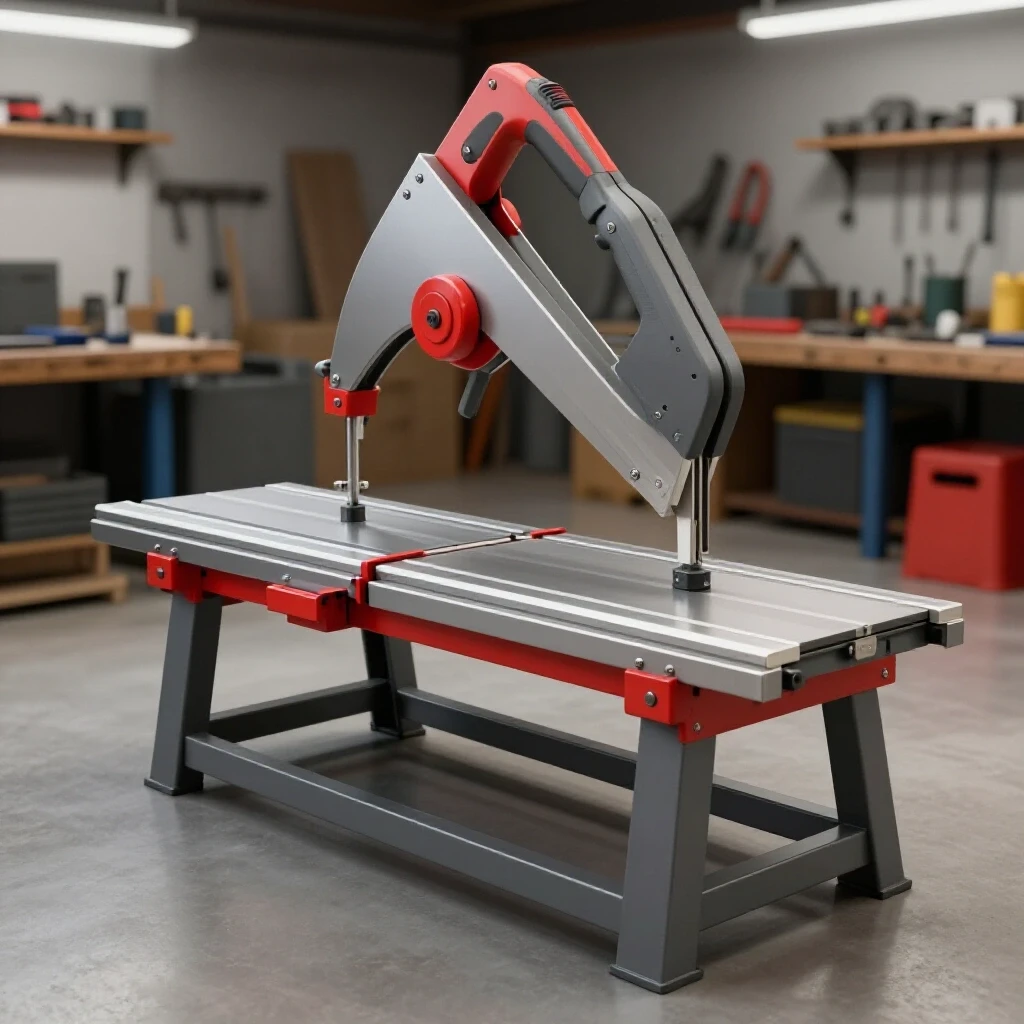
A stable cutting platform is the backbone of any fabrication shop. If your saw is sitting on a flimsy, stamped-steel base or a wooden bench that breathes with the humidity, you will never get a straight cut. In this guide, I will walk you through the process of constructing a heavy-duty, rigid steel stand designed to provide the structural integrity needed for precise material processing. We will focus on material selection, layout accuracy, and weld sequencing to ensure your equipment stays true.
Engineering a Rigid Foundation for Cutting Accuracy
A rigid foundation refers to a support structure that resists torsional twisting and vertical deflection under the weight and vibration of a machine. By using heavy-wall steel and triangulated bracing, we create a platform that prevents the saw frame from bowing, which is a primary cause of blade misalignment during heavy cuts.
When I design a stand, I start with the footprint. A narrow base is a recipe for vibration. For a standard 4×6 or 7×12 bandsaw, I prefer a footprint that extends at least 4 inches beyond the saw’s mounting points on all sides. This wider stance lowers the center of gravity and distributes the weight more evenly. I typically use 2-inch square tubing with a 1/8-inch (11 gauge) wall thickness. It offers a great balance between weight and rigidity.
Interestingly, many builders overlook the floor. No garage floor is perfectly flat. If your stand is bolted together or poorly welded, it will eventually conform to the dips in your concrete. This introduces a twist into the stand, which transfers directly to the saw’s pivot point. To combat this, we must build a frame that is stiffer than the machine it supports.
Calculating Kerf and Cut Allowances for Precision Fits
Kerf is the width of the material removed by a cutting tool, such as a saw blade or a torch. Accounting for kerf ensures that your final pieces match your blueprint dimensions exactly, preventing gaps that cause weak welds or “pulling” during the cooling process as the metal shrinks.
In my shop, I always factor in a 1/16-inch kerf for my bandsaw cuts. If I need a 30-inch leg, I don’t just mark 30 inches and cut. I mark 30 inches and ensure the blade travels on the “waste” side of the line. If you cut down the middle of the line, your part will be 1/32-inch short. While that sounds small, across four legs and four cross-members, those errors accumulate. This leads to a stand that is out of square before you even strike an arc.
- Standard Abrasive Saw Kerf: 3/32 inch to 1/8 inch.
- Bandsaw Kerf: 0.025 inch to 0.035 inch.
- Plasma Cutter Kerf: 1/16 inch to 1/8 inch depending on tip size.
| Cutter Type | Typical Kerf Width | Accuracy Level |
|---|---|---|
| Cold Saw | 0.080″ | High |
| Metal Bandsaw | 0.035″ | High |
| Abrasive Chop Saw | 0.125″ | Low |
| Plasma (Handheld) | 0.060″ – 0.100″ | Medium |
Material Selection and Structural Design
Material selection involves choosing the right steel shapes and thicknesses to handle the static load of the machine and the dynamic forces of the cutting process. Using square tubing for the main legs and angle iron for the mounting surface provides a high strength-to-weight ratio and simplifies the welding process.
I prefer square tubing over angle iron for the main legs because of its torsional strength. Angle iron is great for many things, but it tends to twist under heavy loads. For the top perimeter where the saw actually sits, I use 2-inch by 2-inch by 3/16-inch angle iron. This creates a “cradle” that the saw can bolt into, providing a flat surface for the machine’s base.
Building on this, the thickness of your material determines how much heat it can soak up before it starts to warp. Thinner materials, like 16-gauge tubing, are difficult to weld without significant distortion. By staying with 11-gauge or 3/16-inch plate for mounting tabs, you give yourself a much larger margin for error during the welding phase.
The Role of Leveling Feet in Dampening Harmonic Vibration
Leveling feet are adjustable threaded components attached to the bottom of the stand legs that allow for precise height adjustments on uneven surfaces. They are essential for ensuring the stand remains perfectly level, which prevents the saw from rocking and reduces vibrations that can lead to blade chatter.
I never build a stand that sits directly on the tubing ends. Instead, I weld a 1/4-inch thick plate with a threaded nut (a “bung”) to the bottom of each leg. I then use heavy-duty 1/2-inch threaded leveling feet. This allows me to “dial in” the stand once it is in its final home. If one corner is hanging in the air, the saw will vibrate, and that vibration ruins the surface finish of your cuts.
- Thread Size: 1/2-13 or 5/8-11 for maximum stability.
- Foot Diameter: At least 2 inches to distribute weight.
- Adjustment Range: 1 to 2 inches is usually sufficient for most shop floors.
Strategic Weld Sequencing to Maintain Squareness
Weld sequencing is the planned order in which you apply welds to a structure to balance the heat-induced shrinkage forces. By alternating sides and positions, you can use the cooling of one weld to counteract the “pull” of another, keeping the entire frame aligned and square.
This is where most projects go wrong. When you weld a joint, the liquid metal cools and shrinks. This shrinkage acts like a powerful winch, pulling the metal toward the weld. If you weld all the way around one joint before moving to the next, your stand will be crooked by the time you finish. I use a “staggered” approach. I tack every single joint first, then I weld 1-inch beads on opposite corners of the frame.
As a result of this sequencing, the heat stays localized, and the opposing forces cancel each other out. I always wait for the metal to be cool enough to touch before moving to the next set of welds. It takes longer, but it saves hours of trying to “beat” the stand back into square with a sledgehammer later.
Tack Welding Techniques for Secure Layouts
Tack welding involves making small, temporary welds to hold components in place during the assembly process. Proper tacks must be strong enough to resist the initial heat of the main welding passes but small enough to be easily ground away if an adjustment is needed.
For a stand made of 2-inch tubing, I use four tacks per joint—one on each side. Each tack should be about 1/4-inch long. I always check my squareness after the first two tacks. If the part moved, I can easily snap a small tack and reset it. Once all four tacks are in place, the joint is surprisingly strong and resistant to the “pull” of the final beads.
- Tack Size: 1/4 inch to 3/8 inch for 1/8-inch wall tubing.
- Tack Count: 4 per square tube joint.
- Inspection: Check for squareness after every two tacks.
| Feature | Recommended Specification |
|---|---|
| Material Wall Thickness | 1/8″ (11 Gauge) |
| Squareness Tolerance | +/- 1/16″ across diagonals |
| Tack Weld Spacing | Every 90 degrees on tubing |
| Weld Bead Length | 1″ to 2″ increments |
Cross-Bracing Strategies for Structural Rigidity
Cross-bracing is the addition of diagonal members to a rectangular frame to create triangles, which are inherently more stable shapes. This prevents “racking,” where the frame tilts to one side under load, ensuring the saw remains perfectly upright and the blade tracks consistently through the metal.
If you look at a simple four-legged stand, it is basically a series of rectangles. Rectangles want to become parallelograms. To stop this, I add diagonal braces on the back and sides. You don’t need heavy tubing for this; even 1-inch flat bar or 3/4-inch square tubing works wonders. By connecting the bottom of one leg to the top of the next, you lock the geometry in place.
Interestingly, you only need to brace three sides if you need the front open for storage or foot room. As long as you have two sides and a back braced, the stand will resist racking. This rigidity is what prevents the saw from “leaning” into a cut, which is a common cause of the blade drifting out of vertical alignment.
Mounting Geometry and Surface Flatness
Mounting geometry refers to the precise alignment of the holes and surfaces where the saw attaches to the stand. Ensuring these surfaces are co-planar (on the same flat plane) prevents the saw’s cast-iron base from cracking or twisting when the mounting bolts are tightened down.
When I weld the top mounting rails, I use a straightedge to ensure they are perfectly flat across the span. If one rail is higher than the other, bolting the saw down will actually twist the saw’s frame. I often use shims—thin strips of sheet metal—between the saw and the stand to fill any small gaps before I tighten the bolts. This ensures the saw sits “neutral” and isn’t under tension.
- Place the saw on the completed stand without bolts.
- Check for any “rocking” or gaps at the mounting points.
- Insert shims until the saw is perfectly stable.
- Mark and drill your mounting holes (usually 3/8-inch or 1/2-inch).
- Tighten bolts in a criss-cross pattern, checking for frame flex as you go.
Managing Heat Distortion During Final Assembly
Heat distortion is the permanent warping of metal caused by the uneven expansion and contraction during the welding process. Managing this requires controlling the heat input by using the lowest effective amperage and allowing the workpiece to cool naturally between passes.
In my experience, the biggest mistake is “chasing” a warp. If you see the frame start to pull to the left, don’t immediately weld the right side to pull it back. This often creates “locked-in” stresses that will eventually cause the frame to crack or pop. Instead, use a heat sink—a thick piece of aluminum or copper clamped near the weld—to pull the heat away from the steel.
Building on this, I always keep a “weld log” for complex stands. I mark which joints I’ve welded and in what order. This helps me maintain a consistent heat pattern across the entire project. If I find that the top frame has bowed upward by 1/16-inch, I know I can weld the underside of the cross-braces to pull it back down.
Post-Weld Alignment and Straightening Techniques
Post-weld alignment is the process of checking and correcting any minor distortions that occurred after the metal has cooled. While we aim for accuracy during welding, small adjustments using mechanical force or localized heat can bring the stand back within the required tolerances.
If the stand is slightly out of square (less than 1/8-inch), I use a heavy-duty F-clamp or a bottle jack to apply pressure while the metal is still warm. You can also use “flame straightening,” where you heat a small spot on the “long” side of a warp and let it cool. The shrinking of that hot spot will pull the metal back into line. However, this is an advanced technique and should be used sparingly.
- Maximum Allowable Deviation: 1/16 inch over 4 feet.
- Correction Method: Clamping and “cold” bending for minor errors.
- Verification: Re-check diagonals after the stand has reached room temperature.
Practical Steps for a Successful Build
Now that we understand the principles, let’s look at the actual workflow. I start by cutting all my material at once. This ensures that all four legs are exactly the same length. I then layout the top frame on a flat surface—ideally a welding table, but a flat section of concrete works if you are careful.
- Cut List: 4 legs (30″), 2 long top rails (24″), 2 short top rails (18″), 4 bottom stretchers.
- Layout: Place the top rails and check for squareness using the 3-4-5 triangle method.
- Tacking: Tack the top frame, then the legs to the top frame, then the bottom stretchers.
- Verification: Measure diagonals. If the top frame is 30″ x 20″, the diagonals must be identical.
- Welding: Follow the staggered sequence, welding 1-inch beads at a time.
- Finishing: Grind welds flush on the mounting surface so the saw sits flat.
- Leveling: Install the bungs and leveling feet.
By following this structured approach, you are not just building a table; you are building a precision fixture. The time you spend ensuring the stand is rigid and square will pay off every time you drop the saw blade onto a piece of stock and get a perfectly vertical cut.
Frequently Asked Questions
Why does my saw blade drift even when the stand feels solid? Blade drift is often caused by the saw frame twisting. If your stand is solid but not perfectly flat, bolting the saw down can pull the cast-iron base into a twist. This misaligns the blade guides. Use shims to ensure the saw sits neutral on the stand.
Can I use casters instead of leveling feet? I generally advise against casters for a bandsaw stand if accuracy is your main goal. Casters have “play” in the swivels and rubber wheels that compress. This allows the saw to vibrate and move during a cut. If you must have mobility, use “leveling casters” that have a retractable rubber foot.
What is the best way to check for squareness on a large stand? The most accurate way is measuring the diagonals. Measure from the far left corner to the near right corner, then vice versa. If the measurements are within 1/16-inch of each other, your frame is square. A standard framing square is often not accurate enough for large structures.
How do I prevent the stand from “walking” across the floor? “Walking” is caused by harmonic vibration. Using heavy-wall tubing increases the mass of the stand, which helps dampen these vibrations. Additionally, ensuring all four leveling feet have firm, equal pressure against the floor will keep the stand stationary.
Is it better to bolt or weld the saw to the stand? Always bolt the saw to the stand. Welding the saw’s base directly to the stand can introduce massive heat distortion to the saw’s precision-machined surfaces. Furthermore, bolting allows you to shim the saw for perfect alignment.
What amperage should I use for 1/8-inch square tubing? For MIG welding with .030 wire, I typically stay around 17-18 volts and a wire speed of 250-280 inches per minute. You want enough heat for good penetration but not so much that you blow through or cause excessive warping.
Should I paint the stand before or after mounting the saw? Paint it before, but leave the mounting surfaces and grounding areas clean. A good coat of enamel or “chassis black” paint will prevent rust, which can eventually creep between the saw and the stand and cause alignment issues.
How much does weld shrinkage actually move the metal? On a standard 90-degree joint in 1/8-inch steel, a full-penetration weld can pull the part 1 to 2 degrees out of square. This is why tacking on all four sides and using a staggered weld sequence is non-negotiable for precision work.
Do I need to brace the very bottom of the legs? Yes. I recommend placing your bottom stretchers about 6 inches up from the floor. This provides enough room for your feet when you are working at the saw but keeps the legs from “splaying” outward under the weight of the machine.
Can I use 1-inch tubing for the stand? I find 1-inch tubing to be too flexible for most mid-sized bandsaws. The “flex” in the metal can lead to blade chatter. Stick to at least 1.5-inch or 2-inch tubing for a much more professional, stable result.
(This article was written by one of our staff writers, Robert Kline. Visit our Meet the Team page to learn more about the author and their expertise.)