How to Build a Mobile Drill Accessory Organizer Cart (Plan)
I remember the first time I built a rolling frame for my shop. I had spent four hours meticulously measuring every piece of square tubing. I used a precision square, double-checked my diagonals, and felt confident. Then, I started welding. By the time I finished the last corner, the entire frame looked more like a diamond than a rectangle. One corner had lifted nearly half an inch off the table. That was my first real lesson in the physics of metal: heat is a powerful force that can ruin even the most careful layout.
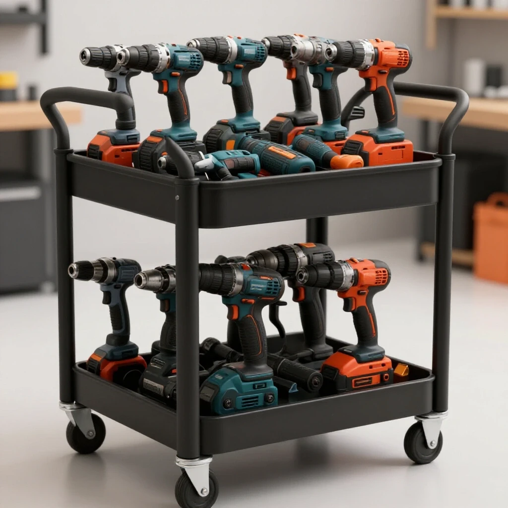
Thirteen years later, after building everything from custom utility trailers to prototype chassis, I’ve learned that fabrication is as much about managing heat as it is about joining metal. When you are constructing a heavy-duty rolling station for your drill bits, chucks, and hole saws, you aren’t just sticking parts together. You are managing thermal expansion and contraction. This guide focuses on the technical reality of building a mobile metal storage unit that stays square, rolls true, and handles the weight of a full accessory collection without buckling.
The Foundation of Precise Metal Layouts
A layout is the blueprint you transfer onto your raw material to guide every cut and weld. It is the most critical stage because an error of 1/16th of an inch at the start can grow into a full inch of misalignment by the time you reach the final assembly.
In my shop, I treat the layout as a sacred process. For a mobile storage project, I start by identifying the “master edge” of my steel. This is the one side that I know is straight, which I use as a reference for all other measurements. If you are using 1-inch or 1.5-inch square tubing for the frame, you must account for the radius of the corners when measuring. I always use a scribe or a fine-point silver pencil rather than a thick soapstone. A soapstone mark can be 1/8-inch wide, which introduces too much room for error.
- Dimensional Tolerance: Aim for +/- 1/16th of an inch across the entire frame.
- Squareness Check: Always measure diagonals. If the distance from the top-left to bottom-right corner matches the top-right to bottom-left, your frame is square.
- Material Prep: Remove all mill scale from the weld zones using a flap disc. Clean metal is essential for consistent heat transfer and deep penetration.
Calculating Accurate Cut Lists and Kerf Allowances
A cut list is a detailed inventory of every piece of metal needed, while kerf is the width of the material removed by the saw blade during a cut. Failing to account for kerf is why many builders find their final frames are shorter than intended.
When I plan a wheeled accessory rack, I start with the overall height, including the casters. If you want a 36-inch tall work surface and your casters are 5 inches tall, your metal frame must be exactly 31 inches. But you also have to subtract the thickness of your top and bottom horizontal rails. If you are using 1.5-inch tubing for the top and bottom, your vertical struts need to be shorter to compensate.
| Cutting Tool Type | Average Kerf Width | Best Use Case |
|---|---|---|
| Abrasive Chop Saw | 1/8 inch (0.125″) | Rough cuts, heavy structural steel |
| Cold Saw | 3/32 inch (0.093″) | High-precision, burr-free cuts |
| Portable Band Saw | 1/16 inch (0.062″) | Versatile, low heat, thin kerf |
| Plasma Cutter | 1/16 to 1/8 inch | Non-linear shapes and thick plate |
I always mark my “waste side” of the line. If I need a 24-inch rail, I line up the saw blade so the teeth just touch the outside of my mark. This ensures the finished piece is exactly 24 inches, and the 1/8-inch of metal turned into dust comes from the scrap side.
Building Workshop Jigs for Frame Squareness
Jigs are temporary structures or fixtures that hold your workpieces in a fixed position while you weld. They are the only way to combat the natural tendency of metal to pull toward the heat of a weld.
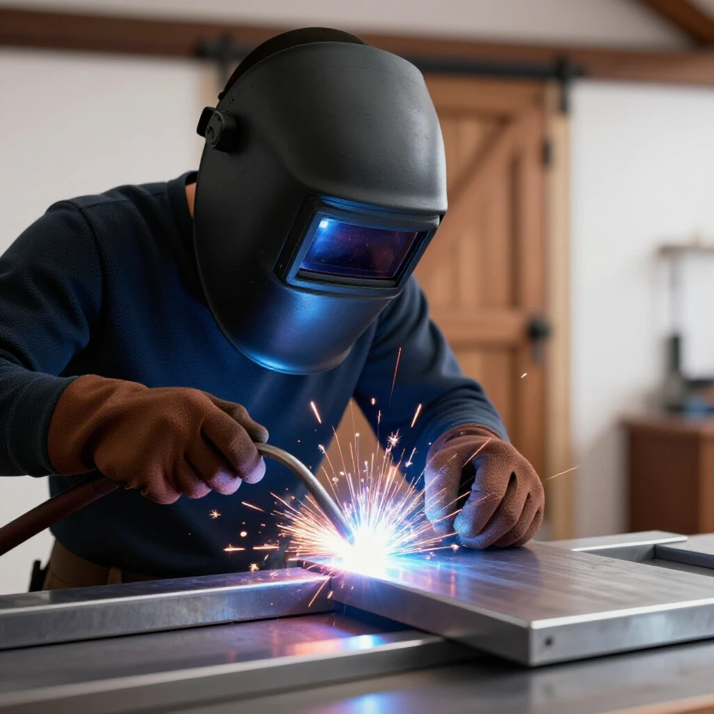
I don’t trust magnets for final alignment. While they are great for holding a piece in place while you reach for your square, the magnetic field can actually cause “arc blow,” where your welding arc wanders unpredictably. Instead, I use a dedicated steel welding table with a grid of holes. I use “dogs” and F-clamps to lock the tubing against a known straight edge.
If you don’t have a professional fixture table, you can build a temporary jig by tacking scrap angle iron to your workbench. This creates a “nest” for your frame. By clamping your square tubing into this nest, you force the metal to stay at a 90-degree angle. Even if the heat wants to pull the joint, the physical restraint of the jig keeps it in check until the metal cools and the stresses stabilize.
Controlling Metal Warping with Strategic Tack Welding
Tack welding involves placing small, temporary beads at the corners of a joint to hold the assembly together before the final welding passes. These tacks act as the “skeleton” of your project.
I’ve seen many builders make the mistake of tacking one side of a frame and then immediately laying a full bead. This is a recipe for a warped mess. When metal melts, it expands; as it cools, it contracts. That contraction is what pulls your frame out of square. To prevent this, I use a “four-point” tacking strategy on every square tubing joint.
- Place a small tack on the inside corner.
- Check for squareness with a machinist’s square.
- Place a second tack on the opposite outside corner.
- Place tacks on the remaining two sides.
- Re-check diagonals before moving to the next joint.
For 1/8-inch wall tubing, your tacks should be about 1/4-inch long. If a tack is too small, the cooling force of a full weld will snap it. If it’s too large, it becomes difficult to “weld over” smoothly during the final pass.
Managing Heat Distortion through Weld Sequencing
Weld sequencing is the planned order of applying beads to balance the thermal stresses across a structure. By jumping from one side of the project to the other, you allow heat to dissipate evenly.
Think of your wheeled storage unit as a series of opposing forces. If I weld the entire front face of the cart at once, the front will shrink, and the whole unit will bow forward. Instead, I use a “staggered” sequence. I might weld the top-left corner, then move to the bottom-right corner. This keeps the total heat input of any one area low.
- Back-stepping: Instead of welding in one long continuous bead, break the joint into segments. Start 2 inches from the end and weld toward the start. Then start 4 inches back and weld toward the 2-inch mark.
- Opposing Joints: If you weld the “inside” of a corner, follow it by welding the “outside” of that same corner. The second weld will pull the metal back in the opposite direction, neutralizing some of the distortion.
- Cooling Periods: I often keep a spray bottle of water or a compressed air nozzle nearby to cool tacks, but I never quench a structural weld. Rapid cooling with water can make the steel brittle. Let the final beads air-cool naturally.
Fabricating Custom Storage for Bits and Chucks
The internal layout of your mobile unit is where the organization happens. This involves welding sheet steel trays and specialized brackets to the frame to hold your drilling accessories.
I prefer using 14-gauge sheet steel for shelves. It is thick enough to handle the weight of heavy hole saw kits but light enough to weld easily to the main frame. When installing these shelves, I use a “stitch weld” pattern. Instead of a continuous bead along the entire shelf—which would almost certainly warp the sheet metal into a potato chip shape—I lay 1-inch beads every 6 inches.
For drill bit storage, I often weld a piece of 2-inch wide flat bar at a 15-degree angle. Before welding it in, I use a drill press to create a series of holes sized for my most-used bits. This “stepped” design makes it easy to see the sizes at a glance.
- Hole Saw Pegs: Weld short lengths of 1/2-inch round bar vertically to a shelf to create “posts” for hole saws to slide onto.
- Chuck Key Hooks: Small 1/8-inch rods bent into a “U” shape and welded to the side of the frame keep chuck keys from getting buried under bits.
- Drawer Slides: If you add drawers, ensure your vertical frame members are perfectly parallel within 1/32nd of an inch, or the slides will bind.
Final Assembly and Caster Attachment
The final step is making the unit mobile. This requires a flat base to ensure that all four wheels touch the ground simultaneously.
I always use caster plates rather than welding the caster stems directly to the tubing. I weld 1/4-inch thick steel plates to the bottom four corners of the frame. These plates should be slightly larger than the caster swivel base. I then drill and tap holes into the plates or use through-bolts. This allows for easy replacement if a caster fails in the future.
Before I burn in the caster plates, I set the frame on my flat welding table. If there is a wobble, I know the frame has warped. I can often “cold-straighten” a minor warp by clamping the high corner down to the table and applying heat to the opposite side of the weld joint to pull it back. Once the frame sits dead flat, I finish the caster installation.
- Level the Base: Ensure the bottom rectangle is flat within 1/16th of an inch.
- Caster Rating: Use casters rated for at least 1.5 times the expected total weight. If the cart will hold 300 lbs of steel and bits, use four 150-lb rated casters.
- Locking Mechanism: At least two casters should have total-lock brakes (locking both the wheel and the swivel) to keep the cart from “walking” while you are searching for a bit.
Actionable Fabrication Framework
To keep your project on track, I recommend using a build log. This helps you track your weld sequence and ensures you don’t miss a critical tack.
- Cut Phase: Verify every piece against the master cut list. Group them by length.
- Layout Phase: Clean all joints to shiny metal. Mark centerlines for all shelves.
- Jig Phase: Secure the base frame to your table. Clamp every corner.
- Tack Phase: Place four tacks per joint. Check diagonals after every four tacks.
- Weld Phase: Follow a staggered sequence. Do not weld more than two joints in the same area without moving.
- Inspection Phase: Use a straightedge to check for bowing in the long rails.
FAQ: Mastering Metal Fabrication for Utility Projects
How do I stop my square tubing from twisting when I weld the corners? Twisting is caused by uneven heat. If you weld only the top and bottom of a horizontal rail, the sides will pull. Ensure you have tacks on all four sides of the tube before welding. Also, try welding the vertical sides of the tube first, as these provide the most structural resistance to twisting.
What is the best way to fix a frame that is out of square after tacking? If the diagonals are off by more than 1/8-inch, you can often “persuade” the frame back into square using a ratcheting pipe clamp (spreader) or a come-along. Apply pressure to the “long” diagonal until the measurements match, then add more substantial tacks to lock it in place.
Should I use MIG or TIG for a workshop accessory cart? MIG is generally faster and better for structural frames like this. It provides good penetration on 1/8-inch tubing and is less likely to overheat the metal because the travel speed is faster. TIG offers more control but inputs more total heat into the part, which can increase warping if you aren’t careful.
Why do my welds look good but the joint still cracks? This is often due to “cold lap” or lack of fusion, usually caused by welding over mill scale or having the voltage set too low. Ensure you grind the area to bright metal and that your weld puddle is actively consuming the edges of both pieces of steel.
How do I calculate the weight capacity of my sheet metal shelves? For a 24-inch span, 14-gauge steel will start to deflect (sag) if you put more than about 50 lbs in the center without reinforcement. To increase capacity, weld a small piece of 1-inch angle iron underneath the center of the shelf as a “spine.”
What is the “neutral axis” and why does it matter for warping? The neutral axis is the theoretical center of a beam where there is no tension or compression. When you weld on one side of a tube, you are applying heat far away from that axis, which causes a leverage effect that bends the tube. Welding symmetrically around the neutral axis minimizes this.
Can I use 1/16th-inch wall tubing to save weight? I wouldn’t recommend it for a mobile tool cart. Thin-wall tubing (16 gauge) is very easy to blow through with a welder and warps much more aggressively than 1/8-inch (11 gauge) material. The extra weight of the 11 gauge provides a much more stable and durable base.
How do I prevent the casters from melting if I weld the plates with them attached? Never weld with the casters attached. The heat will melt the plastic wheels or destroy the grease in the ball bearings. Weld the plates first, let them cool completely to the touch, and then bolt the casters on.
Is it necessary to “V-groove” the joints before welding? For 1/8-inch material, a full V-groove isn’t strictly necessary, but I like to grind a slight bevel (about 30 degrees) on the ends of my tubes. This allows the weld bead to sit flush with the surface of the metal, making it easier to grind smooth for a professional look without sacrificing strength.
How do I ensure the bit-organizer holes stay aligned across multiple rows? Clamp your pieces of flat bar together and drill them all at once on the drill press. This “stack drilling” ensures that every hole is in the exact same position on every bracket, which makes the final assembly look much cleaner.
By following these steps and respecting the way metal reacts to heat, you can build a mobile storage system that is as precise as any professional shop equipment. The key is patience during the layout phase and discipline during the welding sequence. When you finally load it up with your drill accessories and roll it across the floor, you’ll appreciate the effort it took to keep it straight and true.
(This article was written by one of our staff writers, Robert Kline. Visit our Meet the Team page to learn more about the author and their expertise.)