How to Build a Rolling Miter Saw Stand with Wings (Plan)
After eighteen years of reviving forgotten iron, I have learned that a machine is only as precise as the surface it sits upon. I have spent thousands of hours hunched over rusted South Bend lathes and pre-war drill presses, often finding that the greatest enemy of accuracy isn’t just a worn lead screw, but a flexed or unlevel base. When I decided to fabricate a heavy-duty mobile workstation with lateral support extensions for my shop’s primary cross-cutting tool, I applied the same restoration-grade principles I use for rebuilding a 1940s milling machine.
A high-performance tool deserves a foundation that respects its mechanical integrity. Most modern, store-bought solutions are made of thin-walled tubing that vibrates under load and loses its “square” the moment you roll it over a cracked garage floor. For those of us who appreciate the heft of vintage cast iron, we need something more substantial. This project is about creating a rigid, mobile platform that maintains factory tolerances across a twelve-foot span, ensuring that every cut is as true as the day the machine left the foundry.
Evaluating Structural Requirements for Heavy Shop Equipment
This phase involves calculating the static and dynamic loads the station must support to prevent frame deflection and ensure long-term mechanical accuracy.
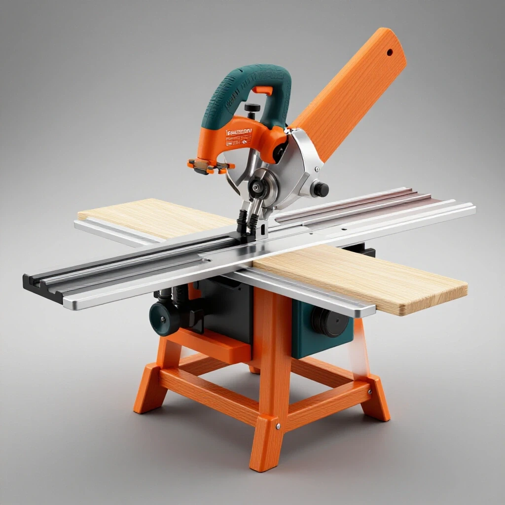
Before I ever strike an arc or cut a piece of steel, I look at the tool’s weight and the leverage exerted by long workpieces. A vintage miter saw, often featuring a heavy cast-iron table, can weigh upwards of 60 to 90 pounds. When you add a ten-foot oak timber to one side, the center of gravity shifts dangerously. I prefer using 2-inch square structural steel tubing with a 1/8-inch wall thickness (11 gauge). This provides the torsional rigidity needed to prevent the frame from twisting, which is the primary cause of inaccurate cuts in mobile setups.
In my experience restoring heavy equipment, I’ve seen how “frame twist” can ruin a machine’s alignment. If the base isn’t stiff, the wings will never stay coplanar with the saw’s table. I approach the base design like a machine bed. I want a wide footprint for stability but a compact enough frame to navigate between my lathe and the welding bench.
| Material Type | Wall Thickness | Weight per Foot | Rigidity Rating |
|---|---|---|---|
| Aluminum Extrusion | 0.080″ | 0.5 lbs | Low (High Flex) |
| Thin-Wall Steel (MIG) | 0.065″ | 1.2 lbs | Moderate |
| Structural Square Tube | 0.120″ | 2.6 lbs | High (Best for Restorers) |
| Solid Cast Iron Bar | N/A | 10.2 lbs | Maximum (Overkill) |
Preparing Reclaimed Components and Rust Mitigation
This process involves removing oxidation and old coatings from salvaged steel or vintage tool parts to ensure clean weld penetration and smooth mechanical movement.
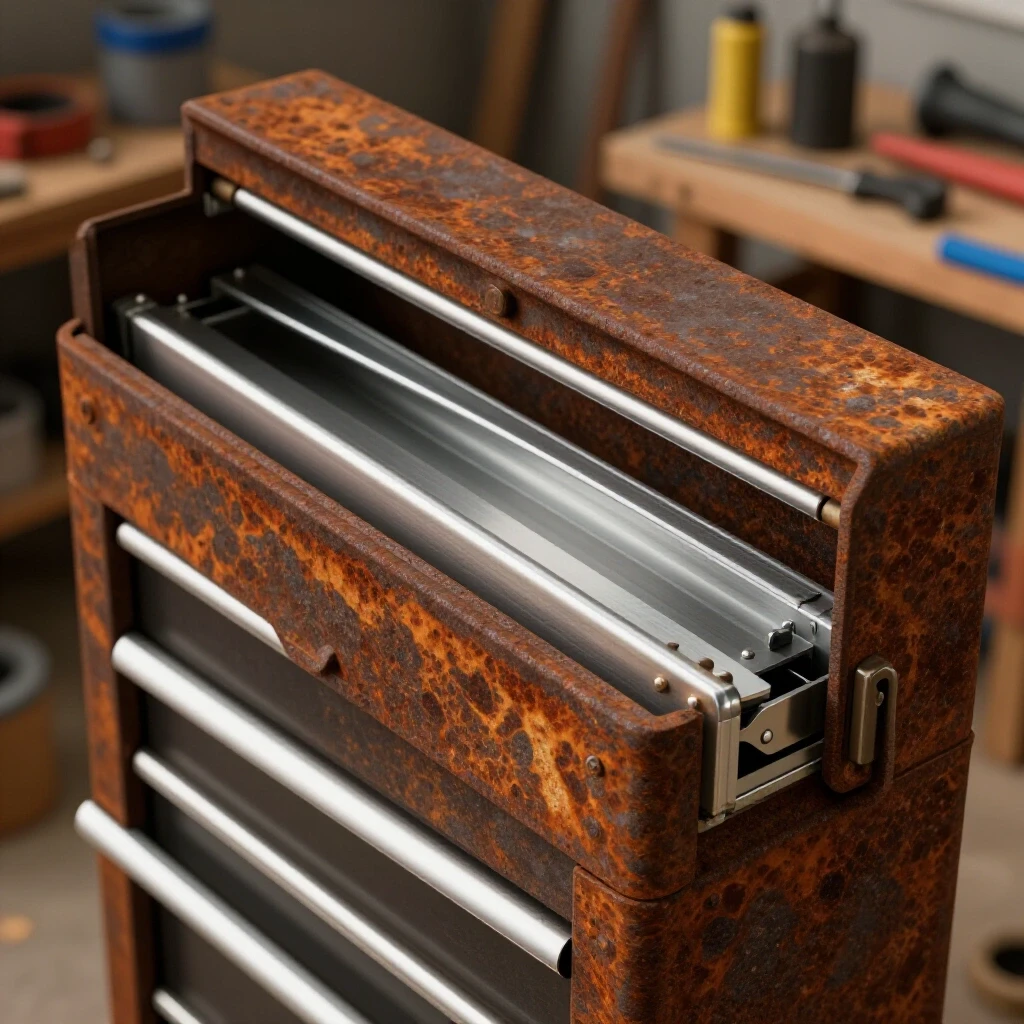
If you are like me, you probably have a “bone yard” of old steel or parts from abandoned projects. Before fabrication begins, every surface must be stripped of “the brown cancer.” For structural steel, I often use a 4.5-inch angle grinder with a knotted wire cup brush. However, for the tool itself—the saw that will sit on this stand—I often turn to more sophisticated methods.
I am a firm believer in electrolysis for cleaning complex cast-iron parts. It is a non-destructive process that uses a 12V DC power supply (like a manual battery charger) and a sacrificial anode to pull rust off the base metal. This is far safer than heavy grinding, which can alter the flat mounting surfaces of a vintage saw. By preserving the original casting’s dimensions, you ensure the tool sits perfectly flat on your new stand.
Rust Removal Method Trade-offs
- Electrolysis: Best for intricate castings. It requires a plastic tub, washing soda, and time. It won’t remove healthy metal, which is critical for maintaining 0.001-inch tolerances.
- Evapo-Rust (Chelating Agents): Excellent for smaller fasteners and threaded rods. It is non-toxic but can be expensive for large frames.
- Wire Wheel / Sanding: Fast for structural tubing but can be messy and risks rounding off sharp edges on precision surfaces.
- Phosphoric Acid: Good for flash-rust prevention, but must be neutralized carefully to prevent paint failure later.
Engineering a Rigid Mobile Framework
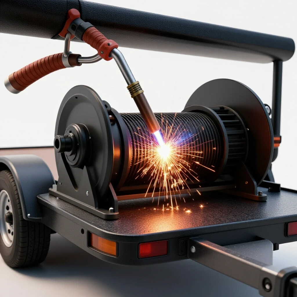
This stage focuses on the layout and welding of the main chassis to ensure it remains square and level under the weight of industrial-grade machinery.
When I build a frame, I treat it like a machine rebuild. I start by cutting my main rails on a horizontal bandsaw to ensure the ends are perfectly square. If your cuts are off by even half a degree, the frame will “diamond” during welding. I use a large machinist’s square to check every corner.
To manage heat distortion—the phenomenon where the cooling weld pulls the steel out of alignment—I use a “tack and check” method. I place small tacks at the corners, re-measure the diagonals, and then proceed with short, staggered beads. This mirrors the way I would reassemble a lathe carriage, ensuring that no single part of the assembly is under internal stress that could cause it to warp over time.
- Cut the base rails: Two long rails for the length, three cross-members for the width.
- Square the assembly: Measure diagonals; they must be within 1/32 of an inch.
- Weld the vertical legs: Use a magnetic square to keep them perpendicular to the base.
- Install the top platform: This is where the saw will rest. It must be perfectly flat.
Designing Precision Extension Wings for Long Stock
These are the lateral support arms that fold out from the main stand to provide a continuous surface for supporting materials up to eight or ten feet long.
The “wings” are the most challenging part of this build. They must be strong enough to hold a 50-pound beam without sagging, yet they need to fold away to save floor space. In my shop, I don’t use cheap door hinges. I prefer to fabricate my own pivot points using bronze sleeve bearings or even poured babbitt if I’m feeling nostalgic.
A sleeve bearing is a simple cylinder of friction-reducing material that allows a shaft to rotate smoothly. By using a 1/2-inch steel pin through a bronze bushing, I can ensure the wings have zero “slop.” If there is play in the hinge, the wing will sag, and your 90-degree cut will actually be 89.5 degrees. I aim for a bearing clearance of 0.001 to 0.002 inches. This level of precision is what separates a restorer’s work from a hobbyist’s weekend project.
Achieving Coplanar Alignment Across the Work Surface
This is the technical process of ensuring that the top of the saw’s table and the tops of the extension wings exist on the exact same horizontal plane.
Once the wings are attached, the real work begins. “Coplanar” means two surfaces are perfectly level with each other. If the wing is higher than the saw, the wood will “teeter.” If it’s lower, the wood will “bow.” I use a 48-foot precision straight edge and feeler gauges to check the gap.
If the wing is slightly low, I use a technique called hand scraping. This is an old-world skill where a hardened steel scraper is used to remove tiny amounts of metal—millionths of an inch at a time. I might scrape the mounting pads of the wing hinges until the straight edge shows no light passing between the saw and the support. I aim for at least 10 to 20 “points per inch” (PPI) of contact. This ensures the weight is distributed evenly across the hinge, preventing future wear.
Alignment Testing Checklist
- Primary Leveling: Level the main stand using a machinist’s level (0.0005″ per foot sensitivity).
- Saw Mounting: Bolt the saw to the center platform, but do not tighten fully yet.
- Straight Edge Check: Lay a 4-foot or 6-foot straight edge across the saw’s throat.
- Wing Elevation: Raise the wings and check for a gap. Use feeler gauges to quantify the error.
- Shim or Scrape: Use thin brass shims or hand-scrape the pivot brackets until the gap is zero.
- Fence Alignment: Ensure the back fence of the saw is perfectly in line with the back edge of the wings.
Mobility Solutions for Heavy-Duty Restoration Stations
This involves selecting and installing high-capacity casters that provide easy movement while maintaining a rock-solid, vibration-free connection to the floor during operation.
A common mistake is using small, plastic casters. In a restoration shop, floors are often covered in metal chips and sawdust. Small wheels will get stuck on a single stray bolt. I use 4-inch polyurethane-on-iron wheels. These have the weight capacity to handle a heavy stand without “flat-spotting” if left in one place for too long.
More importantly, I use “total-lock” casters. These don’t just stop the wheel from rolling; they stop the swivel from turning. When you are manhandling a 12-foot piece of lumber, you cannot have the stand shifting under you. I mount the casters using Grade 8 bolts with nylon-insert lock nuts. Since I often work with obsolete machinery that uses unusual thread patterns, I keep a database of thread pitches, but for this fabrication, standard 3/8-16 UNC fasteners are the most practical and replaceable.
Sourcing and Fabricating Obsolete Fasteners and Hardware
This section addresses the need to create or adapt hardware when standard off-the-shelf components do not fit the specific requirements of a vintage tool integration.
Sometimes, the mounting holes on a 1950s Delta saw won’t match any modern bolt pattern. You might find yourself staring at a 1/2-12 thread—a “Whitworth” or an old “United” standard that isn’t common today. When this happens, I don’t just drill out the hole and ruin the casting. I’ll use my lathe to cut a custom stud with the correct legacy thread on one side and a modern thread on the other.
Preserving the original casting is a point of pride for a restorer. If I’m building a stand for a machine with a unique history, I want the interface between the tool and the stand to be seamless. This might mean using a thread-pitch gauge to identify the old TPI (threads per inch) and then carefully single-pointing those threads on the lathe. It takes more time, but it maintains the mechanical history of the equipment.
Finishing and Functional Corrosion Protection
This final step involves applying a durable, industrial-grade finish to the steel frame to prevent rust without interfering with the precision-machined surfaces.
I don’t care much for “pretty” paint, but I care deeply about rust. For the frame, I use a high-solids machinery enamel. It’s the same stuff found on old South Bend lathes. It’s resistant to oils, coolants, and impacts. However, I never paint the “working” surfaces—the tops of the wings or the pivot points.
For the bare metal surfaces, I use a high-quality paste wax or a dedicated tool surface sealant. This prevents the “flash rust” that occurs in humid shops. I’ve seen beautiful restorations ruined because the owner forgot to protect the bare cast iron. A thin layer of wax also reduces friction, making it easier to slide long boards across your newly aligned lateral supports.
Case Study: The 1946 “Iron Giant” Rebuild
Last year, I rescued a massive 14-inch miter saw from a scrap yard. The base was cracked, and the original stand was long gone. I had to weld the cast iron—a delicate process involving pre-heating the casting to 500 degrees Fahrenheit and using high-nickel welding rods.
Once the saw was functional, I built the mobile station described here. Because the saw was so heavy, I used 3-inch C-channel for the base instead of square tubing. I also incorporated a “leveling foot” system. These are threaded pads that can be screwed down once the stand is in position. This lifts the casters slightly off the ground, turning the mobile stand into a stationary, rock-solid machine base. It was the only way to keep that old iron from vibrating the entire shop.
Final Alignment and Operational Testing
The last step is a series of test cuts to verify that the stand, wings, and saw are all working as a single, calibrated unit.
I start by cutting a “five-cut square” test. This involves taking a square piece of scrap, rotating it 90 degrees after each cut, and then measuring the thickness of the final sliver. If the stand is flexed or the wings aren’t level, the error will multiply. If my final cut is within 0.005 inches over 12 inches, I know the stand is doing its job.
I also check for “bounce.” If I drop a heavy board onto the end of an extended wing, does the saw jump? If so, I need to adjust the support legs or increase the weight of the base. A restorer’s goal is “dead weight”—a machine that feels like it’s bolted to the bedrock of the earth, even if it’s on wheels.
Frequently Asked Questions
Why should I use bronze bushings for the wing pivots instead of standard hinges? Standard hinges often have 0.010 to 0.030 inches of play. Over a four-foot wing, that “slop” translates to a significant sag at the end. Bronze bushings allow you to maintain a 0.001-inch clearance, ensuring the wing stays perfectly level with the saw table every time it is deployed.
How do I handle rust on the vintage saw before mounting it to the stand? Use an electrolysis bath for the best results. Submerge the cast-iron base in a solution of water and sodium carbonate (washing soda). Connect the negative lead of a 12V DC power source to the part and the positive lead to a piece of scrap steel. After 12 to 24 hours, the rust will be converted to a black sludge that brushes right off.
What is the best way to ensure the wings are coplanar with the saw? Use a long, precision-ground straight edge. Lay it across the saw’s table and extend it over the wings. Use feeler gauges to find any gaps. If the wing is low, you can add thin brass shims between the hinge and the frame. If it’s high, you may need to file or scrape the mounting surface.
Is welding structural tubing better than bolting the frame together? Welding creates a monolithic structure that is much more resistant to vibration and racking. However, welding causes heat distortion. You must tack the frame carefully and check for squareness constantly. If you don’t have a welder, use Grade 8 bolts and “gusset plates” at every corner to maintain rigidity.
How do I prevent the stand from moving when I’m cutting large pieces of lumber? Use “total-lock” casters that lock both the wheel and the swivel. For maximum stability, incorporate threaded leveling feet. Once you roll the stand into position, screw the feet down until they take the weight off the casters. This provides a solid connection to the floor.
What steel gauge is best for a heavy vintage saw? 11-gauge (1/8-inch) square tubing is the “sweet spot” for most restorers. It is thick enough to weld easily without burning through, yet rigid enough to support several hundred pounds without significant deflection.
Can I use reclaimed wood for the wing surfaces? While wood is easier to work with, it moves with changes in humidity. For a restoration-grade stand, I recommend using a stable material like Baltic Birch plywood or, better yet, 1/4-inch aluminum plate bolted to a steel sub-frame. This ensures the surface stays flat year-round.
What should I do if my workshop floor is uneven? This is why a rigid frame and leveling feet are essential. A flimsy stand will twist to follow the contour of the floor, pulling your saw out of alignment. A rigid frame with adjustable feet allows you to level the tool regardless of the floor’s condition.
How do I find the correct thread pitch for an old machine’s mounting bolts? Use a thread pitch gauge. These are inexpensive tools with various “teeth” that match different thread counts. If it’s a pre-1930s machine, be aware it might use a non-standard or “proprietary” thread. In those cases, you may need to turn custom fasteners on a lathe.
How do I maintain the stand once it’s built? Keep the pivot points lubricated with a light machine oil (like ISO 32 or 46). Periodically check the alignment with a straight edge, especially after moving the stand over rough ground. Wax the bare metal surfaces once every few months to prevent corrosion.
(This article was written by one of our staff writers, Richard Beaumont. Visit our Meet the Team page to learn more about the author and their expertise.)