How to Weld a Rigid Heavy Stand for Router Lifts (DIY Plan)
When I first pulled a 1940s cast-iron table saw from a collapsing barn in rural Pennsylvania, I didn’t see a rusted heap. I saw a masterpiece of mechanical engineering that just needed a steady place to sit. Over the last 18 years, I have restored more than 40 pieces of industrial machinery, and the most common lesson I have learned is that a precision tool is only as good as the foundation beneath it. If your support structure flexes, your tolerances vanish.
Building a heavy-duty base for precision elevation hardware requires more than just sticking pieces of metal together. It demands a restorer’s patience and a machinist’s eye for detail. Whether you are dealing with a seized vintage assembly or a heavy cast-iron top, the goal is to create a vibration-dampening anchor that respects the history of the tool while providing modern reliability.
Designing the Framework for Massive Machine Stability
Designing a machine base involves calculating the static weight of the tool and the dynamic forces generated during operation. A rigid frame must resist twisting and deflection, ensuring that the precision lifting mechanism remains perfectly square to the working surface even under heavy loads.
In my experience, the biggest mistake is using thin-walled square tubing. For a truly stable platform, I prefer 2-inch or 3-inch square tubing with at least a 3/16-inch wall thickness. This mass is essential for absorbing the micro-vibrations that can ruin a fine finish. When I restored a pre-war shaper, I realized that the original cast legs were far heavier than anything you could buy today. To replicate that stability in a welded stand, you must prioritize wall thickness over external dimensions.
Before you strike an arc, you need a plan. I use a simple grid-based layout on my shop floor or a dedicated welding table. You must account for the height of the operator and the specific footprint of the elevation hardware. A stand that is too tall will be top-heavy and prone to tipping, while one that is too short will cause back strain during long sessions of recalibrating classic equipment precision.
| Material Type | Wall Thickness | Best Use Case | Vibration Dampening |
|---|---|---|---|
| Square Tubing | 1/8 inch | Light-duty mobile bases | Low |
| Square Tubing | 3/16 inch | Standard stationary stands | Medium |
| Square Tubing | 1/4 inch | Heavy industrial restorations | High |
| C-Channel | 1/4 inch | Open-frame structural bases | High |
Strategic Joint Preparation for Heavy-Duty Arc Welding
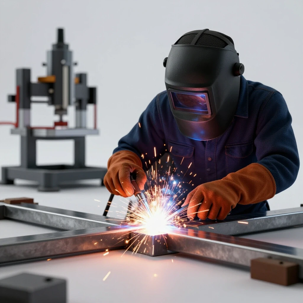
Joint preparation is the process of cleaning and beveling the edges of steel sections to ensure the weld bead penetrates the full thickness of the material. Proper preparation prevents cold-lap joints, which can fail under the weight of heavy cast-iron components or during the vibration of a high-speed motor.
I have seen many beautiful restorations fail because the restorer welded right over mill scale. Mill scale is the dark, flaky layer of iron oxide formed during the hot-rolling process of steel. It is brittle and has a higher melting point than the base steel. If you don’t grind it off, your weld will sit on top of the scale rather than fusing with the metal. I use a 40-grit flap disc to bring the steel to a bright, shiny finish at every joint location.
For 3/16-inch or 1/4-inch material, a 45-degree bevel is non-negotiable. This creates a “V” groove that allows the molten puddle to reach the root of the joint. Without this, you are only holding the pieces together by a thin skin of metal. I learned this the hard way when a stand for a vintage drill press cracked after three years of use. Now, I always ensure a 1/16-inch root gap between pieces to allow for full-depth fusion.
The Importance of Squaring and Tacking
- Clean all mating surfaces to bare metal within two inches of the weld zone.
- Use heavy-duty F-clamps or magnetic squares to hold the tubing at exactly 90 degrees.
- Place small tack welds (about 1/4 inch long) at the corners of each joint.
- Check the frame for squareness by measuring the diagonals; they must be within 1/32 of an inch.
- Adjust the tacks with a dead-blow hammer if the heat has pulled the frame out of alignment.
Controlling Heat and Warpage in Thick-Walled Steel
Thermal distortion occurs when the intense heat of the welding arc causes the metal to expand and then contract unevenly as it cools. In a precision machine stand, even a few thousandths of an inch of warpage can cause the mounting plate for your lifting hardware to bind or sit unevenly.
When I was rebuilding a sleeve-bearing lathe, I learned that heat is both your friend and your enemy. To manage it, you must use a specific welding sequence. Never weld one joint completely before moving to the next. Instead, jump around the frame. Weld the front-left corner, then the back-right, then the front-right. This distributes the heat load and prevents the frame from “parallelogramming” as the metal cools and shrinks.
I also recommend “back-stepping” your welds. This involves starting a bead an inch or two away from your previous stop and welding back toward it. It sounds counter-intuitive, but it significantly reduces the internal stresses in the steel. If you are using a MIG welder, ensure your wire speed and voltage are high enough to produce a “bacon-sizzling” sound, which indicates a stable arc and good penetration.
Achieving Precision Alignment on Fabricated Surfaces
Alignment is the process of ensuring that all mounting surfaces are on the same plane and perfectly level relative to the earth. For machinery restoration, this often requires going beyond what a standard bubble level can provide, sometimes utilizing machinist levels or hand-scraping techniques.
Once the welding is finished, the top of your stand will likely have some slight distortions. This is where machinery hand scraping comes into play. Hand scraping is a manual process of removing high spots from a metal surface using a hardened steel tool. While usually reserved for lathe beds, I often use a modified version of this to flatten the mounting points on a welded stand. I apply a thin layer of “Engineer’s Blue” to a known flat surface, press it against the stand, and then scrape away the blue marks until I achieve a high density of contact points.
If you don’t have the patience for scraping, you can use a series of precision shims. I keep a stock of brass shim stock ranging from 0.001 to 0.015 inches. By placing these between the stand and the cast-iron top, you can dial in the alignment until the lifting mechanism moves without any resistance.
- Standard Leveling: 0.005 inches per foot (Acceptable for rough work).
- Precision Leveling: 0.0005 inches per foot (Required for high-accuracy tools).
- Scraping Density: 10–20 points per square inch (PPI) for a stable mounting base.
Sourcing and Adapting Obsolete Fasteners for Mounting
When mounting vintage machinery to a new steel stand, you will frequently encounter obsolete thread patterns, such as 1/2-12 or 12-24, which are no longer common in local hardware stores. Identifying these threads correctly is vital to prevent stripping out the original cast-iron threads.
During the disassembly of a 1920s bandsaw, I found that many of the bolts were not modern UNC or UNF standards. I highly recommend investing in a high-quality thread pitch gauge and a micrometer. If a bolt feels tight after two turns, do not force it. You are likely dealing with a different TPI (threads per inch) or a different thread angle.
If the original holes in your cast-iron top are damaged, you have two choices: tap them to the next larger modern size or install a threaded insert. I prefer the latter, as it preserves the ability to use the original bolt locations while providing the strength of steel threads. When drilling into old cast iron, remember that it is a porous material. It doesn’t need cutting oil, but it does produce a fine, abrasive dust that can wear out your drill bits quickly.
Checklist for Identifying Legacy Threads
- Clean the internal threads with a stiff nylon brush and compressed air.
- Measure the major diameter of the bolt using a digital micrometer.
- Use a thread pitch gauge to count the peaks per inch.
- Compare the measurements against a vintage thread database (like the 1930s Machinery’s Handbook).
- Test the fit with a new Grade 5 bolt before applying final torque.
Removing Machinery Rust Before Final Assembly
Restoring classic cast iron often starts with a battle against oxidation. Removing machinery rust safely is a prerequisite for a successful build, as you cannot mount precision hardware to a surface that is pitted or covered in scale.
For heavy structural pieces, I swear by the electrolysis bath. Electrolysis uses a low-voltage DC current (usually from a manual battery charger) to pull the oxygen atoms away from the iron. It is a line-of-sight process, so you need to surround the part with sacrificial anodes (scrap steel). Unlike grinding, electrolysis does not remove any of the healthy base metal, which is critical for maintaining factory tolerances.
If the part is too large for a tank, I use a modern water-based chelator like Evapo-Rust. These chemicals work by surrounding the iron oxide molecules and pulling them into solution. It is much safer than the old-school phosphoric acid washes I used 15 years ago, and it doesn’t leave the metal prone to immediate flash-rusting.
| Method | Best For | Risk Level | Time Required |
|---|---|---|---|
| Wire Wheel | Large, flat exterior surfaces | Medium (can round edges) | Fast |
| Electrolysis | Intricate parts, internal threads | Low (safe for metal) | 12–24 hours |
| Chelating Soak | Precision parts, small fasteners | Very Low | 4–12 hours |
| Sandblasting | Heavy structural castings | High (can pit surface) | Very Fast |
Handling Heavy Castings Safely During Construction
The weight of vintage metalworking equipment is both its greatest asset and its most dangerous trait. A single cast-iron table can weigh upwards of 200 pounds, and moving these pieces during the welding and assembly phase requires mechanical assistance to prevent injury or damage to the tool.
I never lift a heavy casting by hand anymore. After a close call with a 14-inch bandsaw spine, I installed a 1-ton gantry crane in my shop. If you don’t have the space for a crane, an engine hoist (often called a “cherry picker”) is the restorer’s best friend. When lifting, use nylon slings rather than chains to avoid marring the machined surfaces or cracking the brittle cast iron.
Always remember that cast iron is strong in compression but weak in tension. If you drop a heavy casting, it won’t dent; it will shatter like glass. When you are fitting the top to your newly welded stand, use long guide pins (bolts with the heads cut off) to help lower the piece into position without pinching your fingers or misaligning the bolt holes.
Rebuilding and Aligning the Elevation Mechanism
Once the stand is welded and the rust is gone, you must focus on the precision lifting hardware itself. This often involves cleaning lead screws, replacing worn bushings, and ensuring the travel is smooth throughout the entire range of motion.
Most vintage elevation systems use an ACME thread lead screw. These are prone to “backlash,” which is the play between the screw and the nut. While you can’t always eliminate backlash, you can minimize it by thoroughly cleaning the threads of old, hardened grease. I use a brass pick to scrape out the “gunk” that acts like a grinding paste, wearing down the threads over time.
For lubrication, stay away from standard automotive grease. It attracts sawdust and creates a sticky mess that will eventually seize the mechanism. I use a dry PTFE spray or a high-quality “way oil” (like ISO 68). Way oil is designed to stay on vertical surfaces and contains tackifiers that keep the oil film from shearing under heavy loads.
- Cleaning: Use a degreaser and a brass wire brush.
- Inspection: Look for “hooked” threads on the lead screw.
- Lubrication: Apply ISO 68 way oil or dry molybdenum disulfide.
- Adjustment: Tighten gib screws until there is no side-play, but the movement remains fluid.
Final Verification and Testing the Integrated System
The final step is to verify that the entire assembly—welded stand, cast-iron top, and elevation hardware—works as a single, rigid unit. This is where your 18 years of patience (or in your case, your recent hard work) pays off.
I start by checking the flatness of the top with a precision straightedge. If I see light under the edge, I know I need to adjust my shims. Then, I run the elevation mechanism through its full travel. It should feel consistent from bottom to top. If it gets tighter at the top, the stand might be slightly twisted, causing the mounting plate to bind the lead screw.
Finally, I perform a vibration test. I place a nickel on edge on the table and turn on the motor (if applicable). If the nickel stays standing, the stand is heavy enough and the welds are solid. If it falls, I look for loose fasteners or areas where I might need to add more mass, such as a lower shelf filled with sandbags or a heavy steel plate.
Tracking Your Restoration Progress
Every machine rescue is a journey, and documenting it is the only way to stay sane when you’re elbow-deep in 80-year-old grease. I keep a dedicated shop log for every project, which helps me remember which thread pitches I found and what the original bearing clearances were.
- Photography: Take “before” photos of every sub-assembly before you turn a single wrench.
- Part Labeling: Use heavy-duty shipping tags for every part. Don’t rely on your memory.
- Measurement Log: Record every tolerance you measure, from shaft diameters to bore sizes.
- Sourcing Notes: Write down where you found that obscure 1/2-12 tap or the specific bearing supplier you used.
- Cost Tracking: Keep a running tally of steel, welding consumables, and replacement parts to see if the project stays within its “rescue” budget.
FAQ: Troubleshooting Your Fabricated Machine Base
What should I do if my stand wobbles after welding? This is usually caused by thermal pull. Do not try to grind the legs. Instead, weld threaded bungs (nuts) into the bottom of the legs and use heavy-duty 5/8-inch leveling feet. This allows you to compensate for both floor irregularities and minor frame twists.
Is it safe to weld directly to the cast-iron machine top? No. Welding steel to cast iron requires specialized nickel rods, pre-heating to 500 degrees Fahrenheit, and a very slow cooling process. It is almost always better to drill and tap the cast iron and bolt it to your steel stand.
How do I know if my weld penetration is deep enough? A good weld should have a consistent ripple pattern and a slight “bulge” on the backside of the joint (if accessible). If the bead looks like a worm sitting on top of the metal, you didn’t have enough heat or you didn’t grind off the mill scale.
Can I use a wooden top instead of cast iron? While wood is easier to work with, it lacks the mass and dimensional stability of metal. For a precision tool, wood will expand and contract with humidity, which will throw off your height settings. Stick with steel or cast iron for the mounting surface.
What is the best way to release a seized height-adjustment screw? Avoid using a long cheater bar, as you will likely snap the screw. Use a 50/50 mix of ATF (automatic transmission fluid) and acetone as a penetrating oil. Apply heat with a propane torch to the surrounding casting (not the screw itself) to expand the hole, then gently tap the screw with a brass drift to break the rust bond.
How thick should the top plate of the stand be? If you are mounting the elevation hardware directly to a steel plate, use at least 3/8-inch or 1/2-inch plate. Anything thinner will flex when you tighten the mounting bolts, which can lead to misalignment.
Why does my lead screw feel “crunchy” after cleaning? You likely have microscopic pits in the metal from past corrosion. If the pitting is minor, you can “lap” the screw by applying a very fine valve-grinding compound and running the nut back and forth, then cleaning it thoroughly. If the pitting is deep, the screw may need to be replaced.
How do I find replacement bearings for a 60-year-old machine? Most vintage machines used standard bearing sizes that are still made today. Wipe away the grease and look for a 4-digit number (like 6203). If the number is gone, use a micrometer to measure the Inner Diameter (ID), Outer Diameter (OD), and Width. You can then look these up in a bearing catalog.
What if the cast iron is cracked? Small cracks can often be “stop-drilled” by drilling a small hole at each end of the crack to prevent it from spreading. For structural cracks, you may need to consult a professional welder who specializes in cast iron “stitch” repairs or brazing.
How do I ensure the stand stays square during welding? Tack weld everything first. Check your diagonals. If they are off, use a ratcheting tie-down strap to pull the frame into square before you lay down the final beads. The tension of the strap will counteract the pull of the cooling weld.
(This article was written by one of our staff writers, Richard Beaumont. Visit our Meet the Team page to learn more about the author and their expertise.)