How to Weld Custom Steel Safety Guards for Machines (Plan)
Walking into a cold shop to face a rusted 1942 South Bend lathe or a seized Buffalo Forge drill press is a ritual I have performed for nearly two decades. There is a specific scent to these rescues—a mix of old sulfurized cutting oil, decaying grease, and the metallic tang of oxidized iron. Over the last 18 years, I have brought more than 40 pieces of neglected equipment back to life, and I’ve learned that the iron never lies. If you treat it with patience, it rewards you with a precision that modern, lightweight machines simply cannot match. However, restoring these giants involves more than just making them spin again; it requires building the protective structures that were often missing or discarded decades ago.
Restoring classic cast iron is a slow process of negotiation. You are negotiating with bolts that haven’t moved since the Truman administration and gears that have been fused by humidity. My approach has always been preservation-first. I don’t just want a tool that looks new; I want a tool that holds factory tolerances of 0.001 inches while ensuring the operator is protected from the massive kinetic energy of open flat-belt drives. Designing and fabricating steel enclosures for these mechanical relics is a vital part of the restoration journey, ensuring these pieces of history remain functional and safe for the next generation of makers.
Evaluating the Structural Integrity of Vintage Machinery
This phase involves a systematic assessment of the machine’s base metal, identifying cracks in cast iron, and determining if the internal components are salvageable. It is the moment where you decide if a machine is a restoration candidate or a parts donor, focusing on structural soundness and the feasibility of fabricating missing protective elements.
Before I ever strike an arc or soak a part in a chemical bath, I look for “the bones.” Cast iron is wonderful for dampening vibration, but it is brittle. I once spent three weeks on a pre-war bandsaw only to find a hairline fracture in the lower wheel housing that made the machine a liability. When evaluating a new find, I use a simple “ring test”—tapping the casting with a small brass hammer. A clear, bell-like ring usually indicates solid metal, while a dull thud often signals a hidden crack or a pocket of internal corrosion.
During this assessment, I also map out where modern steel barriers need to go. Many machines from the early 20th century relied on overhead line shafts and had completely exposed pulleys. To make these tools viable in a modern home shop, we have to plan for custom steel enclosures that follow the machine’s original aesthetic while providing a physical barrier. I look for existing mounting holes in the casting—often used for long-lost factory options—that can serve as anchor points for new steel frameworks.
Strategic Planning for Custom Steel Barriers and Enclosures
This process involves designing physical shields using mild steel plate or tubing to cover exposed moving parts like gears, belts, and pulleys. The goal is to create a rigid, vibration-resistant structure that integrates seamlessly with the machine’s existing cast-iron frame without requiring invasive modifications or drilling new holes into historical components.
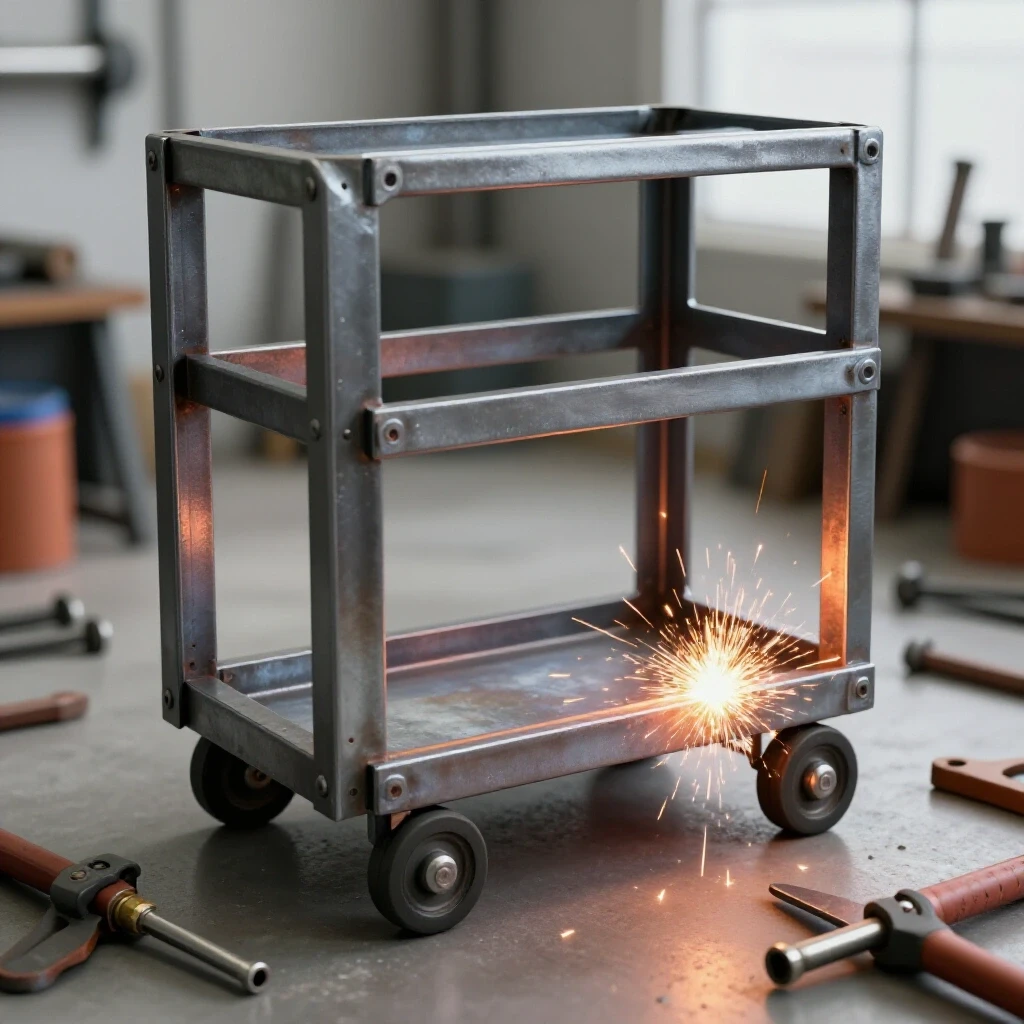
When I plan a new enclosure, I start with cardboard templates. It’s a trick I learned early on: steel is expensive and unforgiving, but cardboard is free. I mock up the entire shroud, ensuring there is enough clearance for belt changes and oiling ports. For the material, I typically choose 11-gauge (1/8 inch) mild steel plate for the main body and 1/2-inch square tubing for the internal skeleton. This combination offers the mass needed to prevent rattling while being easy to weld with a standard MIG or TIG setup.
The design must prioritize rigidity. A flimsy guard is often more dangerous than no guard at all, as it can vibrate into a moving part and cause a catastrophic failure. I focus on basic joint designs, like the corner joint or the T-joint, which provide the best structural integrity for these types of shields. Building a “Plan” for these barriers means thinking three steps ahead—how will I access the grease zerks? How will the belt tensioner move? If the guard blocks a critical maintenance point, it’s a failure of design.
| Material Type | Thickness | Best Use Case | Welding Method |
|---|---|---|---|
| Mild Steel Plate | 1/8″ (11 ga) | Main shroud bodies, heavy gear covers | MIG (GMAW) |
| Square Tubing | 1/2″ – 3/4″ | Internal skeletons, support braces | TIG (GTAW) |
| Expanded Metal | #9 Gauge | Ventilation panels, motor cooling guards | MIG (Plug Welds) |
| Cold Rolled Flat Bar | 3/16″ | Mounting Brackets and Hinges | MIG or TIG |
Why Seized Cast Iron Screws Crack Under Force
This phenomenon occurs when the steel fastener and the cast-iron housing undergo galvanic corrosion, essentially welding themselves together at a molecular level. Attempting to force these parts apart with a wrench often results in the screw snapping or, worse, the cast iron boss shattering, requiring a “Thermal Release Plan” to safely extract the component.
In my years of machine disassembly tips, I’ve broken my share of bolts. The biggest mistake is the “bigger bar” philosophy. When a 3/4-inch bolt in a 1930s drill press won’t move, a longer wrench is just a lever to break the casting. Instead, I use a thermal coefficient release strategy. I apply heat to the surrounding cast iron with an oxy-acetylene torch, not the bolt itself. Cast iron expands at a different rate than steel. By heating the “hole” and keeping the “peg” relatively cool, you can often break the bond of 80 years of rust.
If heat fails, I turn to a 50/50 mix of Acetone and Automatic Transmission Fluid (ATF). This home-brew penetrating oil has outperformed every commercial product in my shop tests. I apply it and let it sit for at least 48 hours, tapping the bolt head occasionally with a hammer to create vibrations that help the fluid “wick” into the threads. Patience is the most important tool in the drawer during this stage of vintage machinery restoration.
Removing Machinery Rust Without Damaging Base Metal
This involves using chemical or electrochemical methods to strip oxidation from the surface of tools while leaving the healthy underlying metal untouched. Methods like electrolysis or chelating agents are preferred over aggressive grinding, as they preserve the original machining marks and the dimensional accuracy of the equipment.
For heavy structural corrosion, I rely on an electrolysis bath. It sounds complex, but it’s remarkably simple: a plastic tub of water, a bit of washing soda (sodium carbonate), and a 12V DC power source like a manual battery charger. I submerge the rusted part, attach the negative lead to the part and the positive lead to a piece of scrap “sacrificial” steel. Within hours, the rust literally migrates off the machine and onto the scrap steel. This method is non-destructive; it won’t eat away at the good metal, which is critical when you’re dealing with precision surfaces.
For smaller, more delicate parts like gears or calibrated dials, I use modern water-based rust chelators like Evapo-Rust. These solutions work through a process where large molecules bond to the iron oxide and pull it away from the base metal. Unlike acid dipping, chelators are pH-neutral and won’t cause hydrogen embrittlement.
- Electrolysis Setup: 12V DC, 2-10 Amps, 1 tablespoon of washing soda per gallon.
- Chelator Runtime: 12 to 24 hours depending on rust depth and ambient temperature.
- Mechanical Cleaning: Use a brass wire wheel (never steel) for stubborn spots to avoid scratching the cast iron.
- Post-Treatment: Immediately dry and coat with a light oil or “flash rust” inhibitor to prevent the metal from turning orange again within minutes.
Welding Custom Steel Guards for Maximum Rigidity
This phase focuses on the actual fabrication of the safety enclosures, using MIG or TIG welding to join the prepared steel components. It emphasizes clean weld beads, proper penetration, and the use of jigs to ensure the final guard is square and fits the machine’s specific dimensions perfectly.
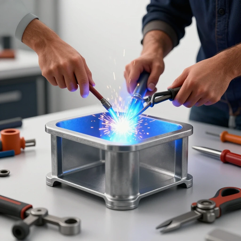
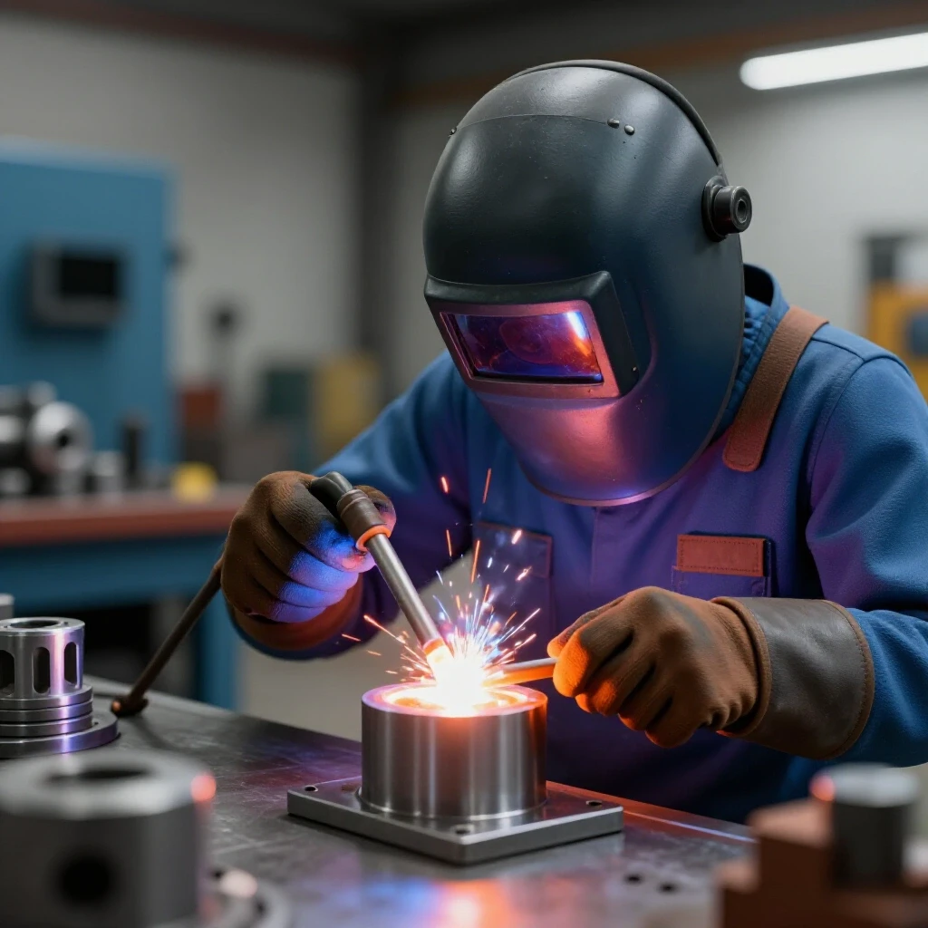
Once the machine is clean, I begin the actual fabrication of the steel barriers. I prefer MIG welding for the main structure because it is fast and handles the slightly imperfect fit-ups common in custom shop work. I set my machine for a “short-circuit” transfer to minimize heat distortion on the 1/8-inch plate. If I’m working on a visible area where aesthetics matter, I’ll switch to TIG welding. TIG allows for a much narrower heat-affected zone and a cleaner bead that requires less grinding.
The key to a successful guard is the mounting system. I never weld directly to the cast iron of the machine. Cast iron has a high carbon content and is prone to cracking when welded with standard steel wire. Instead, I fabricate steel brackets that bolt into existing holes. I use 3/16-inch flat bar for these brackets, ensuring they are beefy enough to hold the weight of the new steel enclosure without flexing.
- Cut the panels according to your cardboard templates using a metal-cutting bandsaw or a plasma cutter.
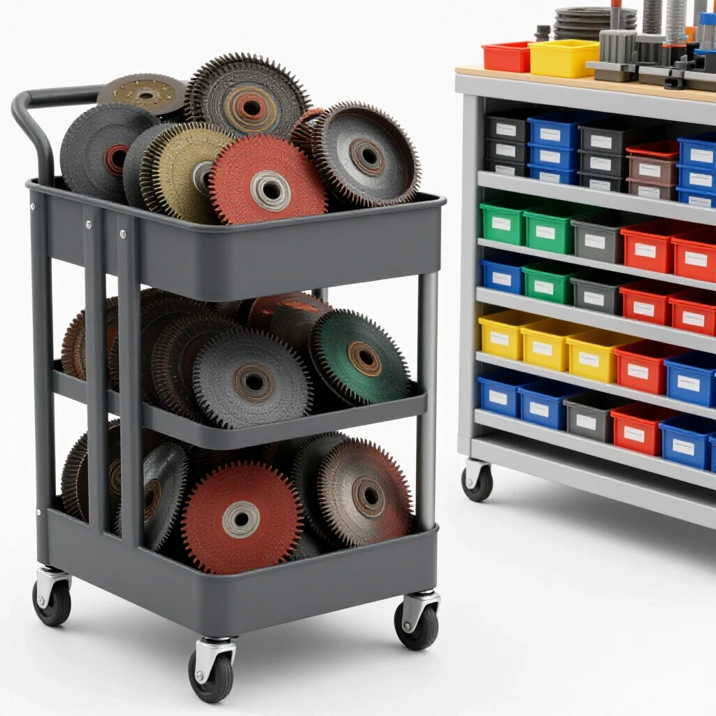
- Deburr all edges with a flap disc; a sharp edge on a safety guard is a cruel irony.
- Tack weld the frame together while it is clamped to a flat welding table to ensure it doesn’t warp.
- Check the fit on the machine before doing the final welds.
- Complete the welds using staggered beads (welding 2 inches at a time in different spots) to manage heat.
Servicing Legacy Bearings and Babbitt Pouring
This involves the inspection and restoration of older bearing styles, such as sleeve bearings or poured Babbitt (a soft white-metal alloy). Restoring these requires checking for scoring, ensuring proper oil grooves are clear, and sometimes melting and repouring the alloy to achieve the necessary 0.001–0.002 inch clearances.
Many of the tools I rescue don’t have modern ball bearings. They use sleeve bearings or Babbitt. Babbitt is a fascinating material—a mix of tin, antimony, and copper that was poured molten into the bearing housing around the shaft. If the bearing is loose, you can sometimes “take up the slack” by removing thin metal shims from the bearing cap. I aim for a clearance of 0.001 to 0.002 inches. If the clearance is larger than 0.005 inches, the shaft will vibrate, ruining the finish on your work.
If the Babbitt is melted or badly scored, it must be repoured. This is a lost art that I’ve spent years perfecting. It involves heating the casting to about 250°F to remove moisture, damming the ends with “Babbitt putty” or clay, and pouring the molten alloy (heated to roughly 650°F) in a single, continuous move. Once cooled, the bearing must be hand-scraped to fit the shaft, a process that requires patience and a sharp carbide scraper.
Precision Alignment and Hand Scraping for Factory Tolerances
This is the final stage of mechanical restoration, where high-spots on mating surfaces are identified using marking blue and removed with a hand scraper. The objective is to achieve a specific number of contact points (usually 10–20 PPI) to ensure the machine components move with extreme accuracy and stay lubricated.
After the rust is gone and the bearings are set, I focus on the “ways”—the flat or V-shaped surfaces the machine parts slide on. Over decades, these surfaces wear unevenly, usually in the middle where the most work is done. I use a precision straightedge and “Prussian Blue” marking compound to find the high spots. I then use a hand scraper to remove a few ten-thousandths of an inch at a time.
This is the most meditative part of restoring classic tool alignment. I aim for a scraping density of 10 to 20 points per inch (PPI). These tiny depressions act as oil reservoirs, preventing the two flat metal surfaces from “wringing” together and seizing. It’s hard work, but it’s the difference between a tool that “just runs” and a tool that can turn a part to within a hair’s breadth of perfection.
| Scraping Metric | Target Value | Purpose |
|---|---|---|
| Points Per Inch (PPI) | 10 – 20 | Oil retention and load distribution |
| Contact Percentage | 40% – 50% | Ensures stability without “stick-slip” |
| Flatness Tolerance | 0.0005″ per foot | Essential for accurate machining |
| Surface Finish | Matte/Flaked | Prevents stiction (static friction) |
Final Assembly and Testing of the Restored Unit
This concluding phase involves reassembling the machine, installing the newly fabricated steel barriers, and performing a “test fire.” It includes checking for vibrations, ensuring the guards do not interfere with moving parts, and verifying that the machine holds its calibrated precision under load.
When I finally bolt the custom steel guards onto the restored machine, it’s a moment of immense satisfaction. I start by checking the belt tracking. If the new enclosure is even slightly misaligned, the belt will rub, creating heat and noise. I use a digital machinist level to ensure the machine is perfectly level on the shop floor; an unlevel machine can actually twist its own bed over time.
The first “power up” is always done at the lowest speed. I listen for the rhythmic “thrum” of the motor and the quiet whir of the gears. I check the temperature of the bearings with an infrared thermometer; they should run warm to the touch, but never hot. If everything stays within the 0.001-inch tolerances I set during the build, I know the restoration is a success. The machine is no longer a piece of scrap; it is a functional piece of history, safe to operate and ready for another 80 years of service.
Actionable Tracking Framework for Restoration Projects
To stay organized during these long-term projects, I use a specific inventory and alignment checklist. This prevents the “where does this bolt go?” syndrome that plagues many first-time restorers.
- Photo Documentation: Take 10 photos for every one part removed. Focus on fastener orientations and shim locations.
- Parts Inventory: Use a spreadsheet to track part names, condition (Good/Repair/Replace), and the location of the replacement (Original/Fabricated/Sourced).
- Thread Database: Identify obsolete thread patterns early. Many pre-1940 machines use “house standards” that aren’t found in modern hardware stores.
- Lubrication Map: Create a chart of every oiling point, specifying the modern equivalent of vintage lubricants (e.g., ISO 32 or 68 Way Oil).
- Alignment Log: Record the initial and final runout measurements for the spindle, tailstock, and bedways.
FAQ: Restoring and Guarding Vintage Metalworking Machinery
How do I know if a rusted machine is worth the effort to restore?
It depends on the “wear vs. damage” ratio. Heavy surface rust is usually fine, but deep pitting on the precision ways or a cracked main casting can be deal-breakers. If the machine is a high-quality brand (like Monarch, Kearney & Trecker, or Cincinnati) and the internal gears are intact, it is almost always worth the rescue.
Can I weld a steel guard directly to the cast-iron machine frame?
I strongly advise against it. Cast iron is high in carbon and can crack due to the thermal shock of welding. It’s much safer to fabricate a steel bracket that uses existing bolt holes or clamps onto the casting. If you must weld to cast iron, it requires specialized nickel rods and a rigorous pre-heat and slow-cool process.
What is the best way to source obsolete fasteners for old tools?
First, check the thread pitch with a gauge. If it’s a non-standard vintage thread, you may have to cut a new bolt on a working lathe or use a thread chaser to clean up the originals. Communities like Practical Machinist or VintageMachinery.org are invaluable for finding members who may have spare “parts machines.”
How thick should the steel be for a belt or gear guard?
For most workshop machinery, 11-gauge (1/8 inch) or 14-gauge (5/64 inch) mild steel plate is ideal. It provides enough mass to stay quiet and enough strength to deflect a broken belt or flying debris without being so heavy that it’s difficult to mount.
Why is hand scraping necessary if the machine looks flat?
“Looks flat” and “machinist flat” are different worlds. Even a surface that appears smooth can have “hills and valleys” that cause the machine to vibrate or lose accuracy. Hand scraping creates a series of high-plateaus to support the load and low-valleys to hold oil, which is essential for smooth, precise movement.
Is electrolysis safe for all types of metal?
It is safe for iron and steel. However, do not use it for “yellow metals” like brass, bronze, or copper, as the process can damage them. Also, never use stainless steel as the sacrificial anode, as it produces toxic hexavalent chromium in the water. Use plain mild steel scrap instead.
What is the most common mistake in building custom machine barriers?
The most common mistake is failing to account for maintenance access. If you have to spend 20 minutes removing a steel shroud just to check the oil or change a belt, you will eventually stop doing that maintenance. Always include hinged doors or “quick-release” thumb screws in your design.
How do I achieve a 0.001-inch clearance on old sleeve bearings?
This is done through the use of precision shims. By adding or removing thin layers of brass or steel shim stock (often as thin as 0.0005 inches) between the bearing halves, you can “pinch” the bearing closer to the shaft until the desired clearance is achieved using a dial indicator to verify the movement.
Should I paint the machine before or after installing the guards?
Paint the machine and the guards separately before final assembly. This ensures that all hidden surfaces are protected from corrosion. Use a high-quality machinery enamel that is resistant to oil and coolants.
What safety gear do I need when welding these steel structures?
Standard welding safety is a must: a #10 or higher auto-darkening helmet, leather gloves, and a flame-resistant jacket. Since you’ll be working around old machinery, ensure the area is clear of flammable oils or old grease before you start throwing sparks.
How do I handle a shaft that is seized inside a Babbitt bearing?
Do not use a sledgehammer. Apply a 50/50 mix of acetone and ATF, then use a hydraulic puller if possible. If it’s still stuck, gently heat the bearing housing to expand the Babbitt slightly. Often, the “stuck” feeling is just old, dried oil that has turned into a glue-like varnish.
Can I use a MIG welder for the entire guard project?
Yes, a MIG welder is perfectly fine for fabricating steel guards. It’s efficient and provides strong joints. Just be sure to grind your welds flush if you want a “factory” look, and always check for full penetration on the structural mounting brackets.
(This article was written by one of our staff writers, Richard Beaumont. Visit our Meet the Team page to learn more about the author and their expertise.)