How to Build a Precision Milling Fixture for Calipers (Tips)
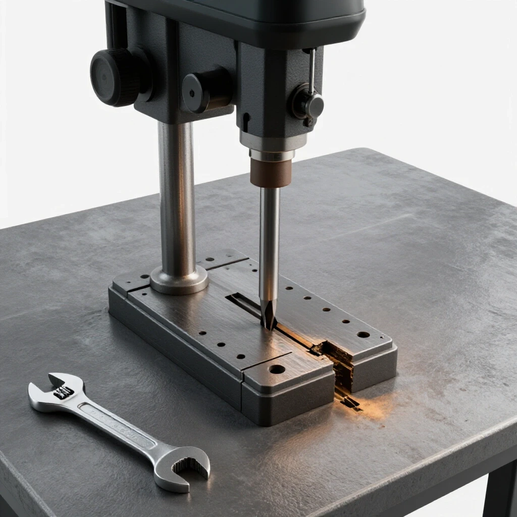
There is a specific scent that fills a workshop when you crack open a gearbox that hasn’t seen the light of day since the Truman administration. It is a heavy mix of congealed whale oil, decomposed felt seals, and the metallic tang of oxidized iron. Over the last 18 years, I have invited that smell into my lungs more times than I can count. I have restored over 40 pieces of industrial history, from massive pre-war lathes to delicate watchmaker’s tools. My journey began with a rusted-solid 1942 Buffalo Forge drill press I found in a scrap heap. That machine taught me that “precision” isn’t something you buy; it is something you recover through patience, technical manuals, and a deep respect for the craftsmen who came before us.
Restoring vintage machinery is not about a quick coat of paint. It is a forensic process. We are often dealing with machines that were built to tolerances of a thousandth of an inch, now buried under layers of “shop rash” and neglect. When we bring these tools back to life, we aren’t just saving money on high-quality cast iron. We are preserving a mechanical lineage. The challenge lies in the fact that many of these tools require custom workholding solutions to even begin the repair process. If you need to mill a new gib or true up a measuring face, you cannot simply throw it in a standard vise and hope for the best. You have to build the means to hold it accurately.
Evaluating the Structural Integrity of Vintage Castings
Before you turn a single wrench, you must determine if the machine is a candidate for restoration or merely a donor for parts. This involves a cold, hard look at the “bones” of the equipment—the heavy cast iron components that provide the mass and dampening required for precision work.
Identifying Fatal Flaws in Aged Iron Assemblies
This is the process of inspecting the main frame and moving slides for cracks, “cold shuts” from the original casting process, or catastrophic impact damage. A hairline crack in a structural casting can often be a dealbreaker for a high-precision restoration.
In my experience, the most common areas for failure are the “ears” of motor mounts and the thin webs of internal castings. I once spent three weeks cleaning a 1930s milling machine only to find a vertical crack in the main column that had been hidden under a thick layer of Bondo and “machinery grey” paint. Now, I use a simple “ring test.” I strip a small patch of paint and tap the casting with a light brass hammer. A healthy casting rings like a bell; a cracked one thuds like wet cardboard.
Mapping the Disassembly Sequence
A systematic plan for taking a machine apart ensures that no parts are bent and that every fastener is accounted for during the long months of restoration. This stage prevents the “where does this go?” panic that occurs during reassembly.
I rely on a “bag and tag” system combined with a digital camera. I take a photo of every sub-assembly from three angles before I remove a single screw. I also maintain a dedicated notebook for each project where I record the order of removal. If a part feels like it is sticking, I stop. I never use a pry bar on cast iron. Instead, I look for hidden “dog point” set screws or tapered pins that are often painted over and invisible to the naked eye.
Strategies for Safely Removing Heavy Machinery Rust
Rust is the primary enemy of the restorer, but removing it too aggressively can ruin the very precision we are trying to save. The goal is to remove the iron oxide while leaving the “virgin” metal and any remaining factory scraping marks intact.
Chemical Chelating vs. Mechanical Abrasion
This involves choosing between modern liquids that “pull” rust away at a molecular level and older methods like wire brushing or sanding. For precision surfaces, mechanical abrasion is almost always a mistake because it rounds off sharp edges and alters dimensions.
I prefer water-based chelating agents for smaller, intricate parts. These solutions are pH-neutral and specifically target iron oxide. For larger castings, I often set up a temporary electrolysis tank. This uses a 12V DC power supply and a sacrificial anode to lift rust out of deep pits that a brush could never reach. It is a slow process, often taking 24 to 48 hours, but it is the gentlest way to treat a 100-year-old surface.
| Method | Best For | Risk Level | Time Investment |
|---|---|---|---|
| Chelating Agent | Small, precision parts | Very Low | 12–24 Hours |
| Electrolysis | Large castings, internal bores | Low | 24–72 Hours |
| Wire Wheel | Non-precision handles/brackets | Moderate | 5–10 Minutes |
| Scouring Pad | Light surface “flash” rust | Moderate | 15–30 Minutes |
Handling Seized Fasteners Without Brute Force
This is the art of extracting screws and shafts that have been fused by decades of corrosion and dried oil. Applying too much torque to a seized bolt in a cast iron hole will almost always result in a snapped fastener or, worse, a cracked casting.
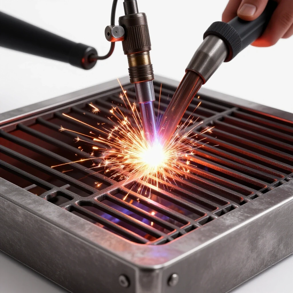
My “holy trinity” for seized parts is heat, vibration, and time. I start by applying a high-quality penetrating oil—not the hardware store variety, but a mixture of acetone and automatic transmission fluid. I let it sit for at least 24 hours. If it still won’t budge, I use a propane torch to heat the surrounding casting, not the bolt. This expands the hole slightly. While the metal is hot, I use a brass drift and a hammer to give the bolt a few sharp raps. This “shocks” the rust bond loose.
Designing Specialized Workholding for Manual Milling
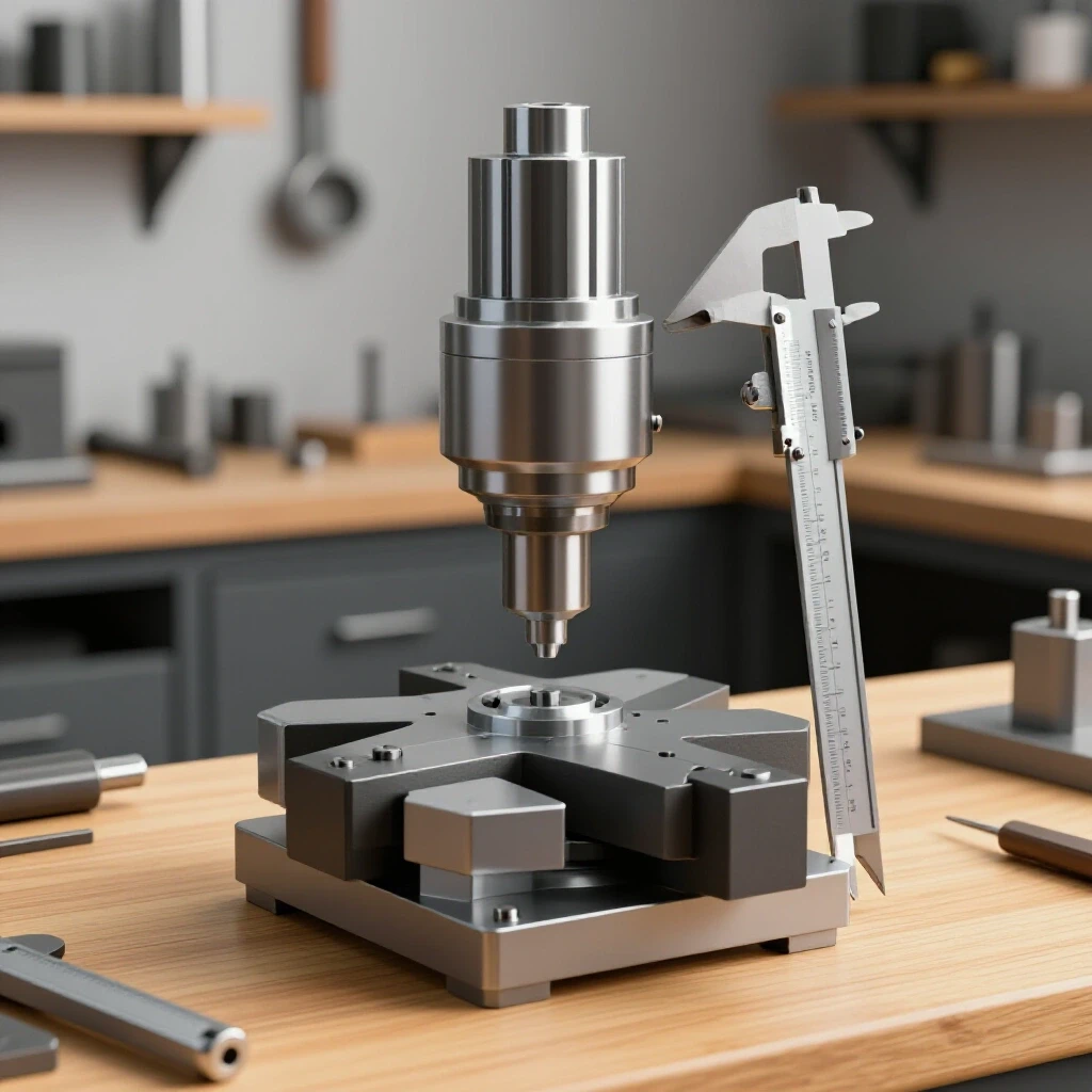
When restoring tools like calipers or small slides, you often need to machine surfaces that are too small or oddly shaped for a standard vise. Creating custom manual milling jigs allows you to hold these delicate components securely and repeatably.
Principles of Three-Point Contact and Stability
This refers to the mechanical rule that a part is most stable when supported at three specific points, preventing it from rocking or vibrating during the milling process. In manual machining, this is essential for maintaining a flat finish.
When I need to true up the jaws of an old vernier caliper or mill a new slot in a small tool, I don’t just clamp it. I build a “sub-plate” from a piece of ground flat stock. I drill and tap this plate with a grid of holes, allowing me to use small “toe clamps” to hold the workpiece from the sides. This leaves the top surface completely open for the milling cutter. By using a sub-plate, I can remove the entire fixture from the mill and return it later with 0.001 inch repeatability.
Material Selection for Precision Jigs
Choosing the right metal for your workholding devices ensures they don’t flex under cutting loads or mar the surface of the vintage tool you are trying to save.
I generally use 6061 aluminum for fixtures that will touch finished surfaces of my vintage tools. Aluminum is soft enough that it won’t scratch the hardened steel of a caliper or a lathe tool bit, but it is rigid enough for light milling passes. If I need a fixture that will be used repeatedly for years, I step up to O1 tool steel, which I leave in its annealed (soft) state. This provides a very stable base that resists the “denting” that can happen with aluminum over time.
Restoring Legacy Bearings and Obsolete Thread Patterns
Many machines from the early 20th century do not use modern ball bearings. Instead, they rely on Babbitt or bronze sleeve bearings. Furthermore, you will often encounter “bastard” thread pitches that haven’t been standard for 80 years.
The Nuances of Sleeve Bearing Clearances
This involves the measurement and adjustment of the gap between a rotating shaft and its stationary housing. If the gap is too small, the machine will seize as it heats up; if it’s too large, the tool will chatter and produce a poor surface finish.
On most vintage lathes and mills, I aim for a bearing clearance of 0.001 to 0.002 inches. I measure this using “Plastigage” or a dial indicator. If the clearance is too wide, I have to “skin” the bearing caps by sanding a few thousandths off the mating surface. If the bearing is completely shot, I have to pour new Babbitt—a lead-tin-antimony alloy. This is a lost art that involves melting the metal to roughly 700 degrees Fahrenheit and pouring it into the pre-heated casting around a mandrel.
Identifying and Cutting Obsolete Threads
This is the process of using a thread pitch gauge and a micrometer to determine the specifications of a non-standard bolt so a replacement can be fabricated. Before the 1940s, many manufacturers used their own proprietary thread standards.
I recently restored a 1910-era drill press that used a 1/2-12 thread. Modern 1/2-inch bolts are 13 TPI (threads per inch). If I had forced a modern bolt in, I would have stripped the original casting. To solve this, I had to set up my lathe to cut the specific 12 TPI pattern. I keep a database of “vintage standards” in my shop, which includes the old Whitworth and Sellers thread profiles. Being able to cut these on a lathe is a vital skill for any serious restorer.
Hand Scraping for Precision Alignment
Hand scraping is the pinnacle of the restorer’s craft. It is the process of using a hand-held carbide tool to remove microscopic amounts of metal to make a surface perfectly flat or to align two parts of a machine.
Understanding Bearing Points and PPI
This refers to the number of “high spots” on a metal surface, measured in Points Per Inch (PPI). A surface that looks flat to the naked eye is actually a mountain range when viewed at a microscopic level.
When I scrape a lathe bed or a milling table, I use a “master surface plate” and a thin layer of “Prussian Blue” dye. I rub the part on the plate, and the dye transfers only to the high spots. I then use the scraper to remove those spots. For a precision machine tool, I aim for 15 to 20 PPI. This creates a surface that is not only flat but also has thousands of tiny “pockets” to hold oil, which prevents the parts from sticking together via “stiction.”
Steps for Aligning a Machine to Factory Tolerances
This is the final assembly phase where you ensure the spindle is square to the table and the slides move linearly without “crabbing” or binding.
- Level the base: I use a precision machinist’s level (sensitive to 0.0005 inches per foot) to ensure the machine isn’t twisted.
- Check the spindle runout: Using a dial test indicator, I measure the “wobble” of the spindle. I look for less than 0.0005 inches.
- Square the head: I use a “cylindrical square” on the table to ensure the vertical axis is perfectly 90 degrees to the horizontal axis.
- Test the backlash: I measure the “play” in the lead screws. On an old machine, 0.005 to 0.010 inches is acceptable, but I strive for less by adjusting the bronze nuts.
Documentation and Parts Sourcing Strategies
The hardest part of a restoration isn’t always the mechanical work; it’s finding the information or parts needed to complete the job. Since many of these companies went out of business decades ago, we have to be creative.
Navigating Obsolete Technical Manuals
This involves searching digital archives, library basements, and collector forums for original “parts explosions” and lubrication charts. A manual tells you not just how the machine goes together, but what kind of oil it needs to survive.
I never use modern “all-purpose” grease in a vintage machine. Old machines were designed for “total loss” oiling systems. Using the wrong lubricant can actually pull grit into the bearings and destroy them. I rely on “Vintage Machinery” archives and similar community-driven databases. If I can’t find a manual, I look for “sister” machines from the same era, as many designs were shared or copied between manufacturers.
Fabricating vs. Sourcing Legacy Components
This is the decision-making process of whether to spend weeks hunting for an original handle or gear, or simply making a new one from scratch.
- Castings: If a casting is missing, I sometimes use a 3D scan of a part from another collector’s machine to create a pattern for a local foundry.
- Gears: Old gears often have “pressure angles” that are no longer standard. I use a gear tooth gauge to verify if it is 14.5 degrees or the more modern 20 degrees before ordering a replacement.
- Fasteners: As mentioned, I almost always make my own “period-correct” fasteners on the lathe to ensure the head shape and thread pitch match the original.
Essential Tracking Framework for Complex Restorations
When you have 200 parts spread across three workbenches, organization is your only defense against chaos. I use a specific tracking sheet for every machine that enters my shop.
| Component ID | Description | Status | Fastener Specs | Notes |
|---|---|---|---|---|
| A-101 | Spindle Pulley | Cleaned | 3/8-16 Square Head | Check for keyway wear |
| B-202 | Cross-slide Gib | Scraped | Mtg. Screws (4) | 18 PPI achieved |
| C-303 | Oil Reservoir | Flushed | N/A | Replace felt wicking |
| D-404 | Tailstock Quill | Polished | 1/2-12 (Proprietary) | Do not use 1/2-13 |
I also maintain a “Lubrication Cross-Reference” sheet. Many old manuals call for “No. 2 Engine Oil” or “Arctic Light,” which don’t exist today. I have mapped these to modern ISO grades (usually ISO 32, 46, or 68) to ensure the machine stays protected.
Final Assembly and Testing Benchmarks
The moment of truth comes when you power the machine for the first time. This should be a gradual process, not a “flip the switch and pray” event.
I start by “barring over” the machine by hand. I want to feel every gear tooth engage and every slide move. If there is any “tight spot,” I stop and investigate. Once under power, I run the machine at its lowest speed for an hour, checking bearing temperatures with an infrared thermometer. A bearing should be “warm to the hand” (around 100–110 degrees Fahrenheit) but never hot. If it climbs above 140 degrees, I shut it down and increase the clearance.
The final test is a “test cut.” I turn a piece of steel and measure the taper. If a 6-inch long bar has less than 0.0005 inches of taper, I know my scraping and alignment work was successful. This is the reward for the months of rust, grease, and frustration—a machine that is technically “better than new” because it has been tuned by a human hand.
Frequently Asked Questions
How do I know if a seized machine is worth the effort? Check the “ways” (the sliding surfaces). If they are deeply scored or rusted to the point of heavy pitting, the machine will require professional grinding or hundreds of hours of hand scraping. If the ways are decent, almost everything else can be fixed or fabricated.
Can I use a pressure washer to clean old machinery? I strongly advise against it. High-pressure water can force grit and moisture into precision bearings and internal gearboxes where it will cause hidden rust. Use a degreaser and a stiff brush, followed by a thorough wipe-down with light oil.
What is the best way to remove “paint-over-rust”? Use a citrus-based paint stripper first to remove the top layers. Once the metal is exposed, switch to a chemical rust remover or electrolysis. Never try to grind off paint and rust at the same time, as the heat can “bake” the paint into the metal pores.
How do I find the original color of a 1920s machine? Look under the nameplates or inside the electrical cabinets. These areas are often protected from sunlight and oil, preserving the original factory pigment. Most “machinery grey” from that era had a slight blue or green tint.
What should I do if I find a cracked casting? For non-structural parts, “stitching” or using high-strength epoxy can work. For structural parts, you need a professional who specializes in “cold-casting repair” or specialized nickel-rod welding. Cast iron is notoriously difficult to weld without it cracking again during cooling.
Is it safe to use modern synthetic oils in old machines? Generally, no. Modern oils often contain detergents that can suspend old grit and circulate it through bearings. Stick to “non-detergent” mineral oils (ISO AW series) which allow contaminants to settle to the bottom of the reservoir where they can be flushed out.
How do I measure thread pitch if I don’t have a gauge? Press a piece of paper against the threads to get an impression. Measure the distance between 10 threads with a ruler and divide by 10. This will give you a rough “pitch” which you can then compare to online thread tables.
What is the most common mistake in machine restoration? Rushing the reassembly. People get excited to see the finished product and skip the final alignment checks or forget to install a small oil wick. A single forgotten wick can ruin a freshly scraped bearing in minutes.
How do I handle “pitting” on a precision surface? If the pitting is minor, you can often “stone” the surface. Use a precision oil stone to remove the raised edges around the pits. The pits themselves will actually act as small oil reservoirs, which isn’t necessarily a bad thing for a manual machine.
Where can I find replacement gears for obsolete lathes? Check specialized suppliers like Boston Gear for standard profiles. If it’s a non-standard “change gear,” you may have to join an online community of owners who often trade or 3D-print patterns for “short run” foundry pours.
How do I safely move a 2,000-pound machine into my garage? Never use a standard floor jack. Use machinery rollers (skates) and a “toe jack.” Always keep the center of gravity as low as possible. If you have to lift it, use a gantry crane or a heavy-duty engine hoist rated for at least twice the machine’s weight.
(This article was written by one of our staff writers, Richard Beaumont. Visit our Meet the Team page to learn more about the author and their expertise.)