Safe Tools for Working With Non-Ferrous Metals (Checklist)
I have spent nearly two decades tearing down machinery to see what manufacturers are hiding under the paint. In my 17 years as a maintenance specialist, I have learned that a shiny logo rarely tells you how a machine will behave when a piece of 6061 aluminum starts to “gum up” your cutters. Most people buy tools based on a spec sheet, but spec sheets do not account for the physics of soft alloys. When you are working with copper, brass, or aluminum, the metal does not just sit there; it reacts to heat and pressure by sticking to your tools or grabbing the workpiece.
I remember a project where I had to mill a series of brass heat sinks on a budget-tier machine. On paper, the motor had plenty of power. In reality, the frame was so light that the harmonics from the brass made the whole machine “sing,” which resulted in a finish that looked like a plowed field. That experience taught me that choosing equipment for soft alloys requires a focus on structural dampening and low-speed torque. You need to look past the marketing hype and evaluate the physical construction of the tool to ensure it can handle the unique demands of non-ferrous materials.
Evaluating Machine Frame Rigidity and Material Dampening
Machine frame rigidity refers to the ability of a tool’s structure to resist bending or vibrating under the stress of a cutting operation. In soft metal work, a rigid frame prevents the tool from “chattering” against the workpiece, which is critical for maintaining accuracy and safety.
When I evaluate a new machine, the first thing I look at is the base. For working with alloys like aluminum or bronze, you want a heavy cast iron frame. Cast iron contains graphite flakes that naturally absorb vibrations, a property known as dampening. Many entry-level machines use thin sheet steel or aluminum extrusions for their frames. While these are light and cheap to ship, they act like a tuning fork. If you are trying to take a deep cut in a block of copper, a thin frame will flex, causing the tool to dig in and potentially kick the part out of the vise.
I look for Grade 25 or Grade 30 gray cast iron. You can often identify lower-quality castings by looking at the unpainted undersides of the machine. If the casting looks porous or has “scabs” from the molding process, the internal stress in the metal might cause the machine to warp over time. A solid, heavy base is the foundation of a safe workshop because it keeps the cutting forces contained within the machine rather than letting them vibrate through your hands.
- Cast Iron Weight: Heavier is almost always better for dampening.
- Ribbing: Look for internal cross-ribbing in the base to prevent torsional twisting.
- Surface Finish: Ground surfaces on the ways should be smooth, not just “milled.”
Assessing Motor Design and Low-Speed Torque
Motor design determines how a tool converts electrical energy into the mechanical force needed to shear through metal. For non-ferrous work, you need a motor that maintains high torque at low speeds to prevent the metal from melting and sticking to your cutting edges.
In my shop, I have seen many “high-horsepower” motors fail because they only reach those ratings at very high RPMs. When you are drilling a large hole in a thick plate of copper, you need to slow the tool down to manage heat. A standard AC induction motor without a gearbox often loses its “grunt” when you slow it down using a simple speed controller. This leads to the tool stalling, which is a major safety hazard.
I prefer brushless DC (BLDC) motors or AC motors equipped with a Vector-Drive Variable Frequency Drive (VFD). These systems use sensors to monitor the motor’s position and provide extra current when they feel the tool starting to bog down. This “back-EMF” feedback ensures that your drill bit keeps turning at a constant speed, even when the “gummy” aluminum tries to grab it. If a machine uses a cheap plastic pulley system to change speeds, be prepared for belt slip and inconsistent performance.
| Motor Type | Torque at Low RPM | Heat Generation | Maintenance Needs |
|---|---|---|---|
| AC Induction (Direct) | Low | High | Low |
| Brushless DC (BLDC) | High | Low | Low |
| Universal (Brushed) | Medium | Very High | High (Brushes) |
| VFD-Controlled AC | Very High | Medium | Low |
Measuring Spindle Runout for Precision Work
Spindle runout, or Total Indicated Runout (TIR), is a measurement of how much a rotating shaft wobbles away from its perfect center. For soft metals, high runout causes uneven tooth loading, which leads to “galling”—where the metal welds itself to your tool.
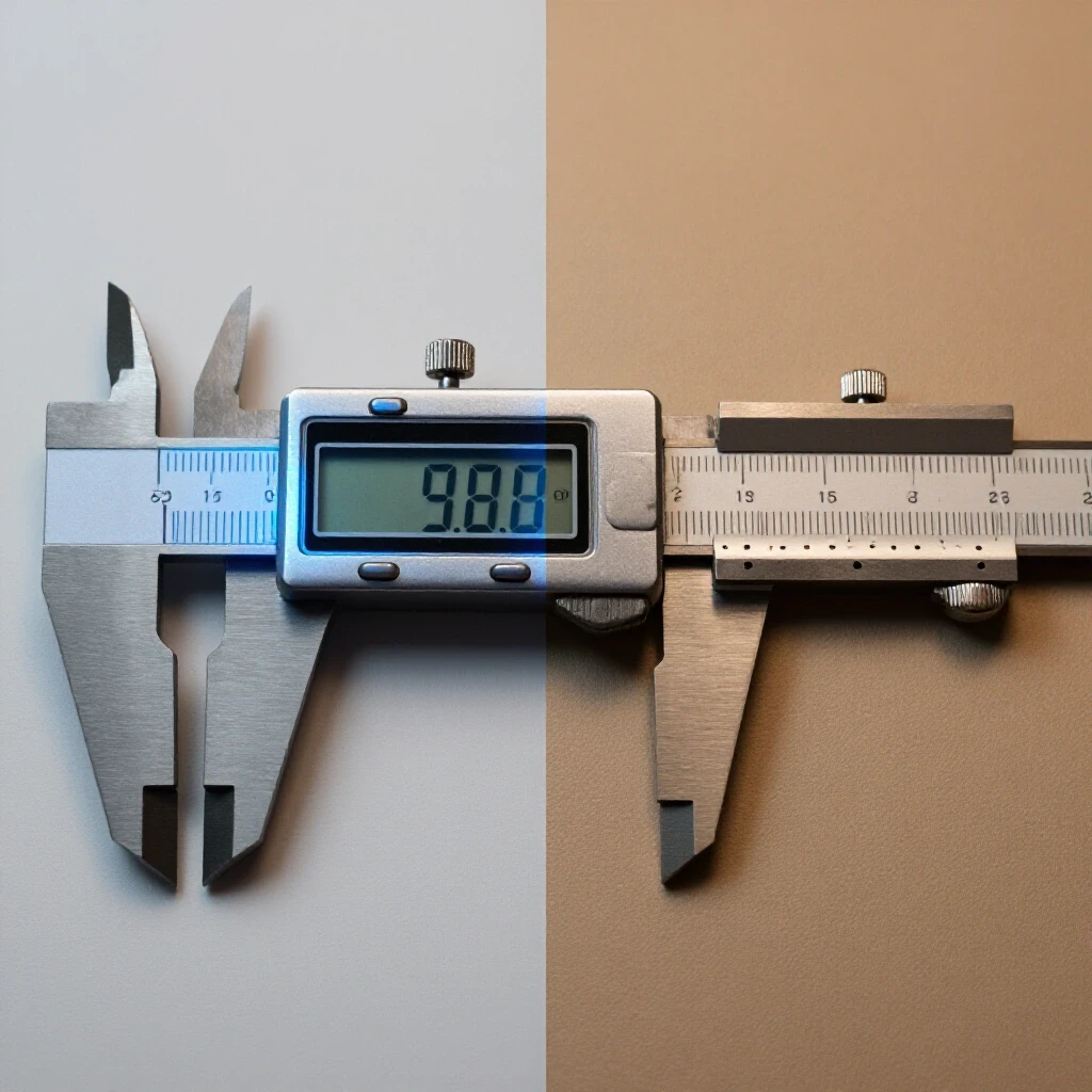
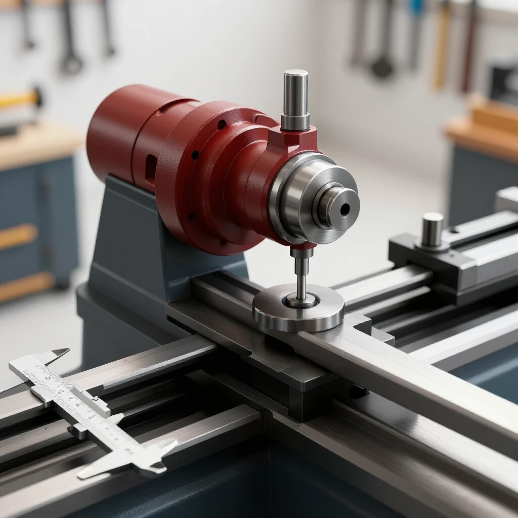
If your spindle has 0.005 inches of runout, and you are using a four-flute end mill, one of those flutes is doing significantly more work than the others. In aluminum, this extra heat causes the chips to soften and stick to the flute, which quickly snaps the tool. When I test a machine, I use a dial test indicator with 0.0001-inch graduations. I place the indicator on the inside of the spindle taper and rotate it by hand.
For a workshop-grade tool intended for brass or aluminum, I look for a TIR of 0.0005 inches or less. If the runout is higher, the machine will never produce a clean finish on soft alloys. This wobble also puts uneven pressure on the spindle bearings, leading to premature failure. Always check the runout before the warranty expires, as a “bent” spindle is a common manufacturing defect in budget machinery.
- Clean the spindle taper thoroughly with a lint-free cloth.
- Mount a high-quality dial indicator on a magnetic base.
- Place the indicator tip against the internal taper.
- Slowly rotate the spindle by hand for one full 360-degree turn.
- Record the total movement of the needle.
Choosing Tool Geometry for Chip Evacuation
Tool geometry refers to the specific angles and shapes ground into a cutting tool, such as a drill bit or end mill. Non-ferrous metals require “sharp” angles and polished surfaces to help the “sticky” chips slide away from the cutting zone.
One of the biggest mistakes I see is using tools designed for general-purpose work on aluminum or copper. General-purpose tools often have a “honed” or slightly blunted edge to survive the hardness of other materials. When these hit soft aluminum, they “plow” the metal instead of cutting it. This creates immense friction and heat. I always look for tools with a high rake angle—meaning the face of the tool is tilted back sharply to shear the metal cleanly.
Polished flutes are another critical feature. If the inside of the drill bit’s groove is rough, the soft metal will catch on the microscopic ridges and start to “build up.” Once that buildup starts, the tool’s diameter effectively increases, the friction skyrockets, and the part can be pulled right out of your clamps. For copper and aluminum, I stick to “O-flute” or “Single-flute” designs for power tools, as they provide the most room for chips to escape.
- Rake Angle: Look for 15 to 20 degrees for aluminum.
- Flute Count: Use fewer flutes (1 or 2) to allow for larger chip clearance.
- Coating: Avoid “TiAlN” coatings, which contain aluminum and can cause the metal to bond to the tool. Look for “ZrN” (Zirconium Nitride) or uncoated, polished carbide.
Inspecting Slide Tolerances and Gib Adjustments
Slide tolerances refer to the “play” or wiggle room between the moving parts of a machine, such as the table of a mill or the carriage of a lathe. In soft metal fabrication, any excess play allows the material to pull the tool into the cut, a dangerous phenomenon called “climb-in.”
When I am refurbishing a machine, I pay close attention to the “gibs.” These are tapered strips of metal that sit between the sliding surfaces. They can be tightened to take up wear. If a machine has “loose” slides, you will feel the tool grab and jerk when you are working with brass. Brass is notoriously “grabby” because of its molecular structure; it wants to pull the cutting tool inward.
To test this, I use a “push-pull” test. With the machine off, I grab the table and try to shake it while watching a dial indicator. If I see more than 0.002 inches of movement, the gibs need adjustment. A machine that cannot hold its slides tight is a liability when working with non-ferrous alloys, as it leads to broken tools and ruined workpieces.
- Gib Type: Tapered gibs are superior to “screw-adjusted” flat gibs because they provide more surface contact.
- Way Lubrication: Look for “one-shot” oiling systems that keep a film of oil between the slides to prevent sticking (stiction).
- Backlash: Measure the play in the lead screws; anything over 0.005 inches on a new machine is a sign of poor assembly.
Bearing Quality and Spindle Preload
Bearings are the components that allow the spindle to rotate under load. Spindle preload is the process of putting a permanent “squeeze” on those bearings to remove all internal play, ensuring the spindle stays rock-solid even when the tool hits the metal.
I have opened up many “budget” machines only to find unbranded, low-grade bearings that were never meant for metalworking. For non-ferrous work, where you might be running at higher RPMs for aluminum or lower RPMs for copper, the bearings need to handle a wide range of thermal expansion. I look for “Tapered Roller Bearings” or “Angular Contact Ball Bearings.” These are designed to handle both the side-to-side (radial) and up-and-down (axial) forces of machining.
If you can hear a “growling” sound when the spindle is running, the bearings are likely failing or were never preloaded correctly. A properly set up spindle should feel smooth and have a slight resistance when turned by hand—this is the preload at work. Without it, the spindle will “float,” and your brass or aluminum parts will have a wavy, inconsistent surface finish.
| Bearing Class | Typical Lifespan (Hours) | Suitability for Non-Ferrous | Precision Level |
|---|---|---|---|
| ABEC-1 (Standard) | 2,000 – 5,000 | Poor | Low |
| ABEC-3 (Precision) | 5,000 – 8,000 | Good | Medium |
| ABEC-7 (High Precision) | 10,000+ | Excellent | High |
| Tapered Roller | 8,000+ | Excellent (High Load) | Medium-High |
Planning for Spare Parts and Long-Term Maintenance
Parts availability is the often-ignored factor in tool safety. A machine that cannot be repaired often ends up being used with “rigged” or “MacGyvered” parts, which is a recipe for an accident in a metal shop.
In my maintenance career, I have seen shops forced to scrap $5,000 machines because a proprietary control board fried and the manufacturer went out of business. Before you buy, check if the machine uses standard industrial components. Does it use a standard NEMA motor mount? Are the bearings a common size that you can buy from a local supply house?
I always recommend buying from brands that provide exploded-view parts diagrams and have a dedicated parts warehouse. When working with non-ferrous metals, you will eventually deal with “chip infiltration”—where tiny bits of aluminum find their way into the electronics or under the way-covers. Being able to easily tear down, clean, and replace a $20 seal or a $50 bearing is the difference between a tool that lasts 20 years and one that ends up in the scrap bin after two.
- Search for the manual online: If you can’t find a parts list before you buy, don’t buy it.
- Identify “Wear Items”: Check the price and availability of belts, brushes, and splash guards.
- Controller Compatibility: For electronic tools, ask if the speed controller can be replaced with a generic version if the original fails.
Establishing a Machine Inspection Routine
An inspection routine is a systematic way to verify that your machinery remains in safe operating condition. For soft metal work, this routine focuses on identifying material buildup and ensuring that all mechanical connections remain tight despite the vibrations of the shop.
I use a simple checklist every time I bring a new tool into the shop or perform monthly maintenance. For non-ferrous metals, the number one enemy is “cold welding.” This is where aluminum dust combines with oil to create a “grinding paste” that eats away at your machine’s precision surfaces. My routine involves checking the “wipers”—the felt or rubber seals that clean the ways as the machine moves. If these are clogged with brass chips, they will scratch the precision-ground surfaces.
I also check the electrical connections. Aluminum chips are highly conductive. If your machine’s motor housing isn’t properly sealed, a stray chip can bridge two terminals and blow the drive board. I’ve seen this happen more often than mechanical failures. A quick vacuuming and a visual check of the seals can save you a $400 repair bill.
- Daily: Wipe down ways and check for chip buildup in the T-slots.
- Weekly: Check belt tension and lubricate all oiling points.
- Monthly: Test spindle runout and check for “play” in the handles or slides.
- Yearly: Inspect motor brushes (if applicable) and check for any signs of casting cracks.
Conclusion
Selecting equipment for working with non-ferrous alloys requires looking beneath the surface. You aren’t just buying a motor and a frame; you are buying a system that must manage heat, vibration, and material adhesion. By focusing on heavy cast iron for dampening, high-torque motors for low-speed cutting, and precision spindles with minimal runout, you can avoid the common pitfalls that lead to ruined projects and unsafe shop conditions. Always prioritize physical build quality and parts availability over digital bells and whistles. A solid, well-maintained machine will provide the consistent performance needed to master the unique challenges of aluminum, brass, and copper.
FAQ
Why does aluminum stick to my cutting tools? Aluminum is a “gummy” metal with a low melting point. During cutting, the friction creates enough heat to soften the metal, causing it to bond to the tool’s surface. This is called “built-up edge” (BUE). Using polished tools with high rake angles and proper lubrication helps prevent this.
Is a heavier machine always better for brass and copper? Generally, yes. Heavier machines, usually made of cast iron, have better “mass dampening.” This means they absorb the vibrations caused by the cutting tool. Brass is prone to “chatter,” and a heavy frame helps keep the tool steady, resulting in a safer and smoother cut.
What is the maximum acceptable spindle runout for aluminum work? For most workshop applications, you should aim for a Total Indicated Runout (TIR) of 0.0005 to 0.001 inches. Anything higher will cause uneven tool wear and a poor surface finish, as the tool will effectively “wobble” through the soft metal.
Can I use the same tools for aluminum and brass? While you can, the ideal geometries differ. Aluminum likes very sharp, high-rake angles to shear the metal. Brass is “grabby” and can actually pull a very sharp tool into the work. Often, tools for brass have a “zero-rake” or even a “negative-rake” edge to prevent the tool from digging in too aggressively.
How do I know if a motor has enough torque for copper? Look for the motor’s “continuous torque” rating rather than just peak horsepower. Brushless DC (BLDC) motors or AC induction motors with a Vector-Drive VFD are best because they maintain their power even at the low speeds required for drilling or milling copper.
What is the danger of “climb-in” when working with soft metals? Climb-in occurs when the workpiece “pulls” the tool into the cut because of play in the machine’s slides. Because non-ferrous metals are soft, the tool can easily dig in deep, stalling the motor or breaking the tool. Keeping your machine’s “gibs” tight is the best way to prevent this.
Are “brushless” motors worth the extra cost for a home shop? Yes, especially for non-ferrous work. Brushless motors are generally more efficient, run cooler, and provide better torque at low RPMs. They also have fewer moving parts to wear out and are better sealed against the conductive dust created when machining aluminum.
How do I prevent aluminum chips from damaging my machine? Ensure your machine has functional “way wipers” to keep chips off the sliding surfaces. Aluminum dust is also conductive, so make sure all electrical cabinets are sealed and that you use a vacuum or brush to remove chips rather than compressed air, which can blow them into sensitive areas.
What should I look for in a machine’s warranty? Look for a warranty that covers the “major castings” for several years and the electronics for at least one year. More importantly, verify that the company stocks replacement parts like belts, bearings, and lead screws so you aren’t left with a “disposable” machine.
Why shouldn’t I use TiAlN coated tools on aluminum? TiAlN stands for Titanium Aluminum Nitride. Because the coating contains aluminum, it has a chemical affinity for the aluminum workpiece. This causes the metal to “cold-weld” to the tool almost instantly. Stick to uncoated carbide or Zirconium Nitride (ZrN) coatings.
(This article was written by one of our staff writers, Steven Brooks. Visit our Meet the Team page to learn more about the author and their expertise.)