How to Safely Wire an Old Single Phase Electric Motor (Fix)
There is a specific scent that greets you when opening a workshop that has been shuttered since the mid-twentieth century. It is a mixture of decomposed grease, cold cast iron, and a faint, metallic tang of oxidized copper. For nearly two decades, I have spent my weekends and late nights hunched over these relics, coaxing life back into machines that the modern world has largely forgotten. My workshop is currently home to a 1940s lathe and a heavy-duty drill press, both of which arrived as lumps of rusted potential.
Restoring these tools is a lesson in patience. You cannot rush a seized pulley or a rusted-shut junction box. My experience with over 40 restoration projects has taught me that the mechanical side of a rescue—the scraping of ways and the pouring of bearings—is only half the battle. The other half is ensuring that the electrical heart of the machine is sound. Bringing a vintage power unit back to life requires a systematic approach to electrical safety and terminal restoration.
Evaluating the Electrical Integrity of Legacy Induction Motors
Assessing the electrical condition of a vintage motor involves a thorough visual inspection and basic testing to ensure the internal components are still viable for operation.
When I first encounter a motor from the 1950s or earlier, I treat it like an unexploded shell. I never assume the internal wiring is safe. Decades of heat cycles and moisture can turn wire insulation into a brittle substance that flakes away at the slightest touch. The goal here is to determine if the motor is a candidate for restoration or if the internal windings have suffered catastrophic failure.
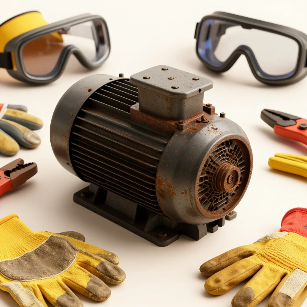
I start by looking at the junction box. Often, these are packed with debris or have been poorly modified by previous owners. I check for “alligator skin” on the wires—a sign that the rubber or cloth insulation has dried out. If the wires inside the motor housing are crumbly, the risk of a short circuit to the cast-iron frame is high. This initial assessment dictates whether we are looking at a simple terminal cleanup or a more involved preservation effort.
Establishing a Safe Physical Foundation for Electrical Work
Creating a secure and isolated environment is the first step in any electrical restoration to prevent accidental energization and physical injury from heavy components.
Safety in a restoration shop is not just about wearing goggles. It is about procedural discipline. Before I even pick up a screwdriver, I implement a lockout/tagout (LOTO) system. This means the power source is physically locked, and I am the only person with the key. Even when working on a motor that isn’t yet plugged in, I treat the workbench as a controlled zone.
Heavy cast-iron motors can weigh upwards of 80 pounds. Dropping one doesn’t just break the motor; it can break your foot or your workbench. I use wooden blocking to stabilize the motor housing, ensuring the junction box is easily accessible without the motor rolling. This physical stability allows me to focus on the delicate task of cleaning terminals without fighting the weight of the machine.
Systematic Disassembly of the Motor Junction Box
Disassembling the external electrical housing requires care to avoid snapping obsolete fasteners or damaging the fragile connection points where internal leads meet external power.
Vintage junction boxes are often held in place by slotted screws that have been rusted in situ for fifty years. I have learned the hard way that forcing these leads to broken heads and hours of drilling. I use a 50/50 mix of acetone and automatic transmission fluid as a penetrating oil. I let it sit for at least 24 hours. If the screw doesn’t budge with a manual impact driver, I apply localized heat with a small butane torch, being careful not to melt any nearby insulation.
Once the cover is off, I document everything. I use a digital camera to take high-resolution photos of the original layout. Even if the wiring is a mess, knowing how it was originally routed helps in the reassembly phase. I then use a vacuum to remove any dust or nests, as compressed air can drive conductive metallic dust deeper into the motor windings.
Restoring Corroded Terminals and Connection Points
Cleaning electrical contact surfaces ensures low resistance and prevents the heat buildup that can lead to premature motor failure or fire hazards.
Corrosion is the enemy of electrical flow. On old induction motors, the brass or copper terminals are often coated in a green patina of oxidation. I use a fine brass wire brush or a fiberglass scratch brush to gently clean these points until the bright metal shines through. I avoid aggressive steel brushes that can leave behind slivers of conductive metal.
If the terminal studs are heavily rusted, I might use a mild chelating agent—a water-based rust remover—applied with a cotton swab. This avoids the mess of a full dip while targeting the specific area of concern. After cleaning, I wipe the terminals with isopropyl alcohol to remove any residues. This ensures that when I finally reconnect the power leads, the contact is as efficient as it was when the machine left the factory.
| Rust Removal Method | Best Use Case | Risk Level |
|---|---|---|
| Manual Wire Brushing | Small terminals and screws | Low (Manual control) |
| Chemical Chelators | Heavily rusted external castings | Low (Non-toxic) |
| Electrolysis | Large, stripped motor housings | Medium (Hydrogen gas) |
| Abrasive Blasting | Non-critical external surfaces | High (Dust ingress) |
Verifying Insulation Integrity with a Multimeter
Insulation testing uses a multimeter to check for continuity and resistance, ensuring that electricity stays within the copper windings and does not leak into the motor frame.
This is where the “fix” becomes data-driven. I use a digital multimeter to perform a continuity check. First, I check for a short to the ground. I touch one probe to a clean spot on the cast-iron motor frame and the other to each of the motor leads. The meter should show an “Open Loop” (OL) or infinite resistance. If I see any continuity here, the insulation has failed, and the motor is a “hot” frame hazard.
Next, I check the resistance of the windings themselves. For a standard single-phase motor, I expect to see a consistent, low resistance reading (usually between 0.5 and 5 ohms, depending on the motor size). If the reading is zero, there is a short; if it is infinite, the winding is broken. These numbers provide the objective proof needed to decide if the motor is safe to move forward with.
Inspecting and Testing Starting Capacitors
Capacitors act as the “kickstarter” for single-phase motors, and their failure is a common reason why old machinery fails to start or hums loudly.
Most vintage single-phase motors utilize a start capacitor, often housed in a “hump” on the side of the motor. These components have a shelf life. Electrolytic capacitors from 40 years ago are likely dried out or leaking. I look for bulging ends or any oily discharge. Even if it looks fine, I test it using the capacitance setting on my multimeter.
If the capacitor is rated for 200 microfarads (µF) and my meter reads 150 µF, it’s time for a replacement. Replacing a capacitor is one of the most cost-effective ways to restore a motor’s starting torque. I always ensure the replacement matches the voltage rating and capacitance of the original, or slightly exceeds the voltage rating for an extra margin of safety.
Re-establishing Safe Power Connections
Final wiring involves connecting the motor to a modern, grounded power cord using appropriate strain relief and secure terminal fasteners.
When I am ready to provide power, I use a modern 14-gauge or 12-gauge three-wire cord. The green ground wire is the most important connection I make. I attach it directly to the motor frame using a dedicated ground screw. I never rely on the junction box mounting screws for a ground path.
For the hot and neutral connections, I use crimp-on ring terminals that match the stud size on the motor. I avoid “twisting and taping” wires, as vibration from the motor can loosen these connections over time. I also install a proper strain relief connector where the cord enters the junction box. This prevents the wires from being pulled out of their terminals if the cord is accidentally yanked.
Checklist for Safe Motor Energization
- Mechanical Check: Rotate the motor shaft by hand. It should spin freely without grinding or resistance.
- Grounding Check: Confirm the ground wire has less than 0.5 ohms of resistance to the motor frame.
- Fastener Check: Ensure all terminal nuts are snug but not over-tightened to the point of stripping.
- Clearance Check: Verify that no bare wires are touching the junction box cover.
- Enclosure Check: Replace the junction box cover and ensure all gaskets are in place to keep out dust.
- Isolation Check: Ensure the machine is not touching any other conductive surfaces during the first test.
Why Cast Iron Junction Boxes Require Special Handling
The brittle nature of vintage cast iron means that junction boxes can easily crack if fasteners are over-torqued or if the box is struck.
In my 18 years of restoration, I’ve seen many beginners crack a motor housing by trying to pry off a stuck junction box cover. Cast iron does not bend; it shatters. When dealing with these parts, I use a “tink” test. A light tap with a small hammer should produce a metallic ring. A dull thud often indicates a hidden crack or a heavy build-up of grease that needs cleaning.
If a mounting tab is broken, I don’t try to weld it with a standard MIG welder. Cast iron requires high-nickel rods and pre-heating. Often, for a non-structural part like a junction box, a cold-metal repair with high-strength epoxy is a safer way to preserve the original part without risking further heat-related stress cracks in the motor frame.
Aligning the Motor for Optimal Operation
Once the electrical path is restored, the motor must be physically aligned with the machine’s drive system to prevent vibration and bearing wear.
A motor that is electrically perfect can still fail if it is misaligned. I use a precision straightedge to ensure the motor pulley is in the same plane as the machine’s drive pulley. Even a 1/16-inch offset can cause the belt to “walk” and put lateral pressure on the motor bearings.
I also check the motor mounts. Many old machines used rubber vibration isolators that have since turned to stone. Replacing these with modern equivalents can significantly reduce the noise of a restored lathe or drill press. I use a digital inclinometer to ensure the motor is level, which helps maintain the proper oil film in sleeve bearings.
| Bearing Type | Typical Clearance | Recommended Lubricant |
|---|---|---|
| Sealed Ball Bearing | N/A (Replace if noisy) | Lifetime Grease |
| Bronze Sleeve Bearing | 0.001″ – 0.0015″ | ISO 32 or 46 Spindle Oil |
| Babbitt Bearing | 0.002″ – 0.003″ | Heavy Way Oil or SAE 20 |
Lessons from a 1947 South Bend Lathe Motor Restoration
Early in my career, I rescued a 1/2 HP motor that had been sitting in a damp basement for thirty years. The motor hummed but wouldn’t turn. I assumed it was a seized bearing. After disassembling the unit, I found the bearings were fine, but the centrifugal start switch—a mechanical device inside the motor—was welded shut by corrosion.
This taught me that “electrical” fixes often have a mechanical component. I had to carefully sand the contact points of the start switch with 600-grit paper and apply a tiny drop of de-oxidizing cleaner. Once the switch could move freely, the motor started perfectly. It was a reminder that in vintage machinery, every system is interconnected. You cannot ignore the mechanical state of the electrical components.
Final Safety Verification Before the First Run
The first time you apply power to a restored motor is a high-stakes moment that requires a specific safety protocol.
I never just “plug it in.” I use a fused power strip or a dedicated circuit breaker. I stand to the side of the motor, never directly in line with the shaft or the belt drive. I wear safety glasses and hearing protection. My hand is always on the “off” switch or the plug, ready to disconnect power at the first sign of smoke, a harsh smell, or an unusual vibration.
I run the motor for only five seconds initially. I then unplug it and feel the housing. It should be cool. I check the junction box again to ensure no connections have shifted. If everything is stable, I run it for a longer duration, monitoring the temperature and sound. A healthy motor should have a consistent purr, not a rhythmic growl.
Maintaining the Restoration for the Long Term
A restored motor is not a “set it and forget it” component; it requires ongoing monitoring to ensure the safety measures remain effective.
Every six months, I open the junction box of my most-used machines. I look for signs of heat—discolored insulation or “cooked” smells. I also re-torque the terminal nuts, as the heating and cooling cycles can sometimes cause them to back off. Keeping the motor clean is also vital. Dust acts as an insulator, trapping heat and shortening the life of the internal windings.
I also keep a logbook for each machine. I record the resistance readings and the date the capacitor was replaced. This data is invaluable for troubleshooting future issues. If the resistance of the windings starts to creep up over the years, I know that the insulation is slowly degrading, and I can plan for a replacement or a professional rebuild before the motor fails catastrophically.
Technical Resources for the Vintage Restorer
Finding information on motors that haven’t been manufactured in half a century is a challenge. I rely on a few specific resources to bridge the gap between obsolete tech and modern safety.
- VintageMachinery.org: An incredible repository of scanned manuals and motor nameplate data.
- Old Woodworking Machines (OWWM) Forum: A community of experts who have seen every possible motor configuration.
- The “Audels Educators” Series: Specifically the books from the 1940s and 50s, which explain the theory of induction motors in plain language.
- Local Electric Motor Shops: While they mostly do industrial work, the older technicians often have a wealth of knowledge on “legacy iron.”
- Digital Multimeters with Min/Max Functions: Essential for capturing the inrush current during the starting phase.
Frequently Asked Questions
What should I do if the wires coming out of the motor windings are crumbling? If the insulation is failing right at the point where the wires enter the motor’s internal coils, it is a high-risk situation. You can sometimes slide heat-shrink tubing over the leads if there is enough length, but if the brittleness extends into the windings, the motor may need a professional rewind or replacement to be safe.
How can I tell if my motor is a “start-induction” or “capacitor-start” type? Look for a cylindrical housing on the outside of the motor. If it has one, it’s likely a capacitor-start motor. If the motor is a smooth cylinder with no external “hump,” it might be a split-phase motor that uses a mechanical start switch instead of a capacitor.
Is it safe to use a motor that has a slight “tingle” when I touch the frame? Absolutely not. A “tingle” indicates that electricity is leaking to the frame, likely due to failed insulation. This is a potential “stray voltage” hazard that can be fatal under the right conditions. You must stop using the motor immediately and identify the source of the ground fault.
Can I replace a cloth-covered wire with modern plastic-insulated wire? Yes, and you should. Modern THHN or MTW wire is much more resistant to heat, oil, and moisture than the original cloth and rubber insulation. Just ensure you use the same or a larger wire gauge (lower AWG number).
Why does my motor hum but not spin when I turn it on? This is usually caused by a failed start capacitor, a stuck centrifugal switch, or seized bearings. Unplug the motor and try to spin the shaft by hand. If it spins freely, the issue is likely electrical (capacitor or switch). If it’s hard to turn, the bearings are the culprit.
How do I clean a junction box that is filled with old grease and sawdust? Use a vacuum first to remove loose debris. Then, use a mild degreaser on a rag to wipe down the interior. Avoid spraying liquids directly into the motor. If the grease is hardened, a plastic scraper can help remove the bulk of it without scratching the metal.
What is the best way to label wires during disassembly? I use small pieces of masking tape and a fine-point permanent marker. I number each lead and the corresponding terminal. Taking a photo before you remove anything is the most reliable “label” you can have.
Does it matter which way I connect the hot and neutral wires to a single-phase motor? On many old motors, the leads are interchangeable for rotation, but for safety, the “hot” (black) wire should always be the one that is switched or fused. The “neutral” (white) should return to the source. Always prioritize the ground (green) connection to the frame.
How do I know if the motor bearings need oil or if they are “sealed for life”? Look for small oil cups or “Gits” fliptop oilers near the shaft ends. If you see them, the motor has sleeve bearings that require regular oiling. If there are no oil ports, it likely has sealed ball bearings which cannot be serviced and must be replaced when they wear out.
Can I use a modern power cord on a motor from the 1930s? Yes, and it is a recommended safety upgrade. Modern cords have better insulation and include a dedicated grounding conductor, which many 1930s cords lacked. Ensure the cord’s amperage rating meets or exceeds the motor’s nameplate requirements.
What is the risk of using an ungrounded motor in a garage workshop? Garages often have concrete floors that can be slightly damp, making them a path to ground. If a fault occurs in an ungrounded motor, your body could become the path for the electricity to reach the floor. A proper ground wire provides a safer, low-resistance path that will trip the breaker instead.
How do I remove a pulley that is rusted onto the motor shaft? Apply penetrating oil and let it soak. Use a proper gear puller rather than prying with a screwdriver, which can bend the shaft. If it’s still stuck, apply heat to the pulley hub (not the shaft) to expand it slightly, then try the puller again.
(This article was written by one of our staff writers, Richard Beaumont. Visit our Meet the Team page to learn more about the author and their expertise.)