How to Build a Mobile Plasma Cutter Cart With Tank (Plan)
I remember the first time I tried to build a mobile base for my workshop equipment. I had spent three hours meticulously measuring and cutting square tubing, convinced that my layout was perfect. As soon as I finished running the final beads on the lower frame, I set it on the floor, and it wobbled like a three-legged dog. One corner was nearly half an inch off the ground. I had ignored the reality of weld shrinkage, and the heat had pulled my frame into a parallelogram.
Thirteen years of prototype fabrication have taught me that metal is a living thing when you introduce heat. Whether you are building a utility trailer or a custom rolling station for your plasma cutter and gas bottle, the physics remain the same. If you don’t account for the way steel moves, your project will fight you every step of the way. This guide focuses on the structural logic and sequence needed to build a stable, square, and mobile unit that can handle the weight of a power source and a high-pressure cylinder without distorting under its own tension.
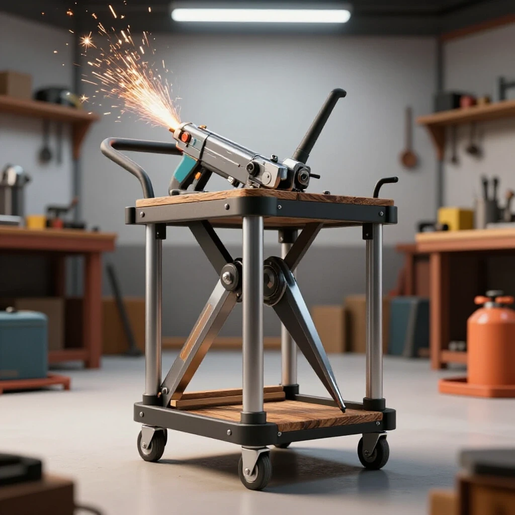
Planning Your Material List and Cutting Strategy
A successful build begins with a comprehensive roadmap that accounts for material thickness, blade kerf, and the weight capacity of your components.
I prefer using 1.5-inch square tubing with a 1/8-inch wall thickness for the main skeleton. It offers a high strength-to-weight ratio and is thick enough to weld easily without burning through. When planning your cuts, you must account for the “kerf”—the actual width of the material removed by your saw blade. A standard abrasive chop saw might remove 1/8 inch, while a cold saw might only take 1/16 inch. Over ten cuts, that’s a significant discrepancy that can throw off your total dimensions.
- Main Frame: 1.5″ x 1.5″ x 1/8″ Square Tubing
- Shelving: 10-gauge or 12-gauge mild steel plate
- Tank Cradle: 1″ x 1/8″ Flat bar for the safety strap
- Casters: 5-inch polyurethane wheels (two locking swivel, two fixed)
| Cutter Type | Typical Kerf Width | Dimensional Impact per 10 Cuts |
|---|---|---|
| Abrasive Chop Saw | 0.125″ (1/8″) | 1.25″ total loss |
| Cold Saw | 0.062″ (1/16″) | 0.625″ total loss |
| Portable Band Saw | 0.035″ | 0.35″ total loss |
| Plasma Cutter (Handheld) | 0.040″ – 0.060″ | Varies by speed |
Calculating Dimensional Tolerances for Custom Fabrication Projects
Dimensional tolerance is the allowable limit of variation in a physical dimension; in garage fabrication, we generally aim for a tolerance of +/- 1/16th of an inch.
When I draft a plan, I calculate my “inside-to-inside” measurements first. If your plasma cutter is 12 inches wide, your shelf needs to be at least 12.5 inches wide to allow for airflow and ease of placement. I always add a 1/16-inch “fudge factor” to my cut list for every joint. This ensures that if my cut is slightly long, I can grind it down, rather than being stuck with a gap that requires a massive bridge weld.
Layout Mastery and Squaring the Foundation
Achieving a square frame requires a flat reference surface and the use of geometric checks like the 3-4-5 rule to ensure 90-degree intersections.
Before I ever strike an arc, I verify my layout. I use a dedicated steel fabrication table, but if you’re working on a concrete floor, you must verify it is level. A frame built on an uneven floor will inherit that twist. To check for squareness, I measure the diagonals of my rectangular base. If the distance from the front-left corner to the back-right corner matches the front-right to the back-left within 1/16 of an inch, the frame is square.
Using Workshop Jigs and Fixtures for Alignment
Fixtures are temporary tools, such as clamps, blocks, or dedicated tables, used to hold workpieces in a fixed position to prevent movement during the joining process.
I don’t trust magnets alone. While they are great for a quick hold, they don’t have the clamping force to resist the pull of a cooling weld. I use heavy-duty F-clamps and pieces of 2×2 angle iron to create “external squares” that I clamp my tubing into. This physical restraint is your first line of defense against metal warping solutions.
- Clamping spacing: Place a clamp every 6 to 8 inches if you are working with thin sheet metal.
- Fixture blocks: Use scrap pieces of 1/8-inch plate to shim your tubing if your work surface isn’t perfectly flat.
- The 3-4-5 Rule: For larger frames, measure 3 feet on one side, 4 feet on the other; the diagonal must be exactly 5 feet.
The Science of Weld Sequencing Layout to Prevent Warping
Weld sequencing is the strategic order of applying welds to balance the thermal stresses and shrinkage forces that naturally occur as the metal cools.
When you weld one side of a joint, the metal expands as it heats and then shrinks as it cools. This shrinkage is more powerful than the expansion. If you weld all four sides of a tube joint in a clockwise circle, the frame will almost certainly pull out of square. I use a “cross-pattern” or “star-pattern” sequence, similar to tightening lug nuts on a car wheel.
Why Weld Shrinkage Warps Square Structures
Angular weld shrinkage occurs because the top of the weld bead (the crown) contains more molten metal than the root, causing the joint to pull toward the face of the weld as it cools.
In my early days, I would finish one entire corner before moving to the next. Now, I tack the entire project first. A tack weld should be about 1/2 inch long and placed at the corners of each joint. These tacks act as tiny anchors. If I see a corner starting to pull, I can “cold-set” it (hit it with a hammer or use a jack) before the final welds lock the distortion in place.
| Weld Sequence Step | Purpose | Result |
|---|---|---|
| Initial Tacking | Anchors the frame in a square position. | Minimizes initial movement. |
| Opposite Corner Welding | Balances the heat pull across the frame. | Neutralizes directional warping. |
| Back-stepping | Welding in short segments in the opposite direction of travel. | Reduces accumulated heat in one area. |
| Stitch Welding | Leaving gaps between short beads. | Lowers overall heat input. |
Structural Considerations for Gas Cylinder Integration
Designing a secure mount for a compressed gas cylinder requires a low center of gravity and robust mechanical restraints to prevent tipping.
A full 80cf or 125cf gas tank is heavy and top-heavy. When building the rear section of the cart, I extend the base frame 8 to 10 inches past the main uprights. This “porch” keeps the weight of the tank between the wheels. If you place the tank too high or too far forward, the cart becomes a tipping hazard when you hit a crack in the shop floor.
- Tank Base: Use a piece of 3/16-inch plate for the tank floor to handle the concentrated weight.
- Safety Chains: Weld two heavy-duty eye bolts at the 1/3 and 2/3 height marks of the tank.
- Caster Placement: Ensure the rear casters are positioned directly under or slightly behind the tank’s center of gravity.
Accurate Square Cuts and Joint Preparation
A square cut is the foundation of a strong weld; gaps larger than 1/16 of an inch require more filler metal and introduce more heat, increasing the risk of distortion.
I always use a square to mark all four sides of my tubing before cutting. If you’re using a portable band saw, it’s easy for the blade to “walk” or tilt, resulting in a cut that isn’t plumb. After cutting, I use a flap disc on an angle grinder to remove the mill scale (the dark grey coating on new steel) at least one inch back from the joint. Welding over mill scale leads to porosity and weak joints.
Metal Layout Tips for Complex Assemblies
Layout involves transferring your blueprint dimensions onto the raw material using scribes, markers, and measuring tools with high precision.
- Use a Scribe: A Sharpie line is nearly 1/16 of an inch wide. A carbide-tipped scribe creates a line that is much more precise.
- Mark the “Waste” Side: Always put an “X” on the side of the line where the saw blade should travel so you don’t accidentally cut your piece short by the width of the kerf.
- Center Punching: Before drilling holes for casters or handles, use a center punch to create a dimple. This prevents the drill bit from wandering.
Executing the Build: Step-by-Step Assembly
This phase moves from raw parts to a structural skeleton, focusing on the order of operations to maintain alignment.
Step 1: The Base Frame
Lay out the four pieces of the lower rectangle. Clamp them to your table. Check the diagonals. Tack each corner on the top side only. Re-check the diagonals. If it moved, a light tap with a dead-blow hammer will bring it back. Once square, tack the bottom and sides.
Step 2: Uprights and Shelving
Weld the vertical supports. Use a magnetic square to hold them, but verify with a manual square. I often cut a “spacer block” out of scrap wood or metal to ensure the height between the bottom shelf and the middle shelf is identical on all four corners.
Step 3: The Tank Rack
The rear “porch” for the cylinder should be welded to the main frame using gussets. A gusset is a triangular piece of plate that reinforces a 90-degree joint. Since the tank rack will experience significant leverage forces, these gussets prevent the weld from fatigue-cracking over time.
Step 4: Caster Plates
Don’t weld the casters directly to the frame. Weld 1/4-inch thick plates to the corners of the frame, drill and tap them, or use through-bolts. This allows you to replace a damaged caster easily. Ensure the plates are level; if one plate is higher than the others, the cart will wobble.
Correcting Heat Distortion and Final Straightening
Even with the best sequencing, some warping is inevitable; post-weld correction involves using controlled heat or mechanical force to return the project to its intended shape.
If I finish the cart and find a slight twist, I use “flame straightening.” I heat the side of the tube opposite the weld that pulled it. As that heated spot cools, it shrinks and pulls the metal back toward the center. It’s a delicate process. Alternatively, for minor wobbles, I might use a large C-clamp to pull the frame into square against the table and then add a small reinforcing brace.
- Tack weld count: At least 4 tacks per square tube joint (one on each face).
- Heat control: If the metal is glowing bright red for more than a few seconds, you are putting too much heat into the joint.
- Cooling: Never quench a weld with water to cool it down quickly. This makes the steel brittle and can cause the weld to crack. Let it air cool.
Actionable Tracking Framework for Your Build
To stay on budget and on schedule, I use a simple log to track my progress and costs. This helps me avoid the “mid-project stall” where I run out of material or motivation.
- Material Log: Record every length of steel purchased and the price per foot.
- Cut List Checklist: Cross off each piece as it’s cut and deburred.
- Weld Sequence Map: Draw a quick sketch of your frame and number the joints in the order you plan to weld them.
- Alignment Log: Record the diagonal measurements after tacks and after final welds.
Conclusion
Building a mobile station for your cutting equipment is a rite of passage for many fabricators. It’s a project that demands both structural integrity and aesthetic precision. By respecting the physics of heat, using physical fixtures rather than just magnets, and following a disciplined weld sequence, you can create a tool that serves your shop for decades.
The key is to move slowly during the layout phase. An extra thirty minutes spent checking for square and ensuring your cuts account for kerf will save you hours of grinding and “fixing” a warped frame later. Start with the base, trust your measurements, and remember that in fabrication, the preparation is 90% of the work. The welding is just the final 10%.
FAQ
What is the best way to ensure the cart doesn’t wobble on a garage floor? The most effective way is to use high-quality adjustable casters or to ensure your base frame is perfectly flat during the tack-welding stage. If your floor is uneven, three-point contact is always stable, but for a four-wheeled cart, you must build the frame on a known flat surface (like a welding table) and use shims to correct any manufacturing defects in the casters themselves.
Can I use 1/16-inch wall tubing to save weight? I don’t recommend it for a cart carrying a gas cylinder. The weight of the tank and the plasma unit can exceed 150 lbs. Thin-walled tubing is prone to “oil-canning” and can easily warp or blow through during welding. Stick to 1/8-inch (11-gauge) for a durable shop fixture.
How do I calculate the center of gravity for the tank? Generally, you want the tank’s weight to sit as low as possible. Position the tank base no more than 6 inches off the ground. The center of gravity for most gas cylinders is roughly at the midpoint of their height. By extending the wheelbase behind the tank, you ensure the center of gravity stays between the front and rear axles.
Should I paint or powder coat the cart? For a shop environment, a high-quality spray-on primer and enamel paint are usually sufficient. Powder coating is more durable but makes it difficult to weld on future modifications, like extra tool hangers or cable wraps, which you will inevitably want to add later.
What size casters are best for a mobile shop cart? I recommend 5-inch diameter wheels. Smaller wheels (2 or 3 inches) tend to get stuck on metal shavings, zip ties, or cracks in the concrete. Polyurethane wheels are ideal because they don’t develop flat spots like rubber but offer more grip than hard plastic.
How do I prevent the sheet metal shelves from rattling? Instead of welding the entire perimeter of the shelf, use 1-inch stitch welds every 4 inches. This reduces heat warp. To stop vibration, you can also apply a thin bead of silicone or specialized automotive seam sealer between the shelf and the frame before welding.
Is it necessary to weld a handle onto the cart? Yes, but place it at a comfortable height (usually 36 to 40 inches). Ensure the handle is on the opposite side of the swivel casters for better steering control, or use swivel casters on all four corners for maximum maneuverability in tight spaces.
How do I account for the weight of the cables and hoses? Cables for plasma cutters are heavy and can pull the cart over if they are all draped on one side. Build “J-hooks” or wraps on both sides of the cart to balance the load and keep the floor clear of tripping hazards.
What happens if my frame is out of square after welding? If it’s off by more than 1/8 inch, you may need to cut the welds on one corner with a thin zip-disc, re-square the frame using a ratcheting strap or a jack, and re-weld it. This is why tack welding and checking squareness at every step is so critical.
Do I need a floor in the cart, or can I just use the frame? A solid floor (sheet metal) is better for the plasma cutter because it prevents sparks and grinding dust from being sucked into the machine’s cooling fans from below. Always try to protect your electronics from the debris of the shop.
(This article was written by one of our staff writers, Robert Kline. Visit our Meet the Team page to learn more about the author and their expertise.)