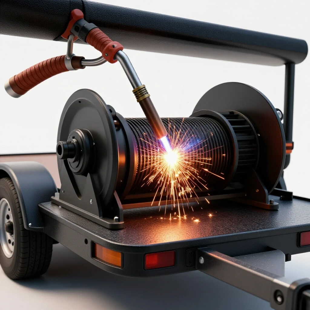
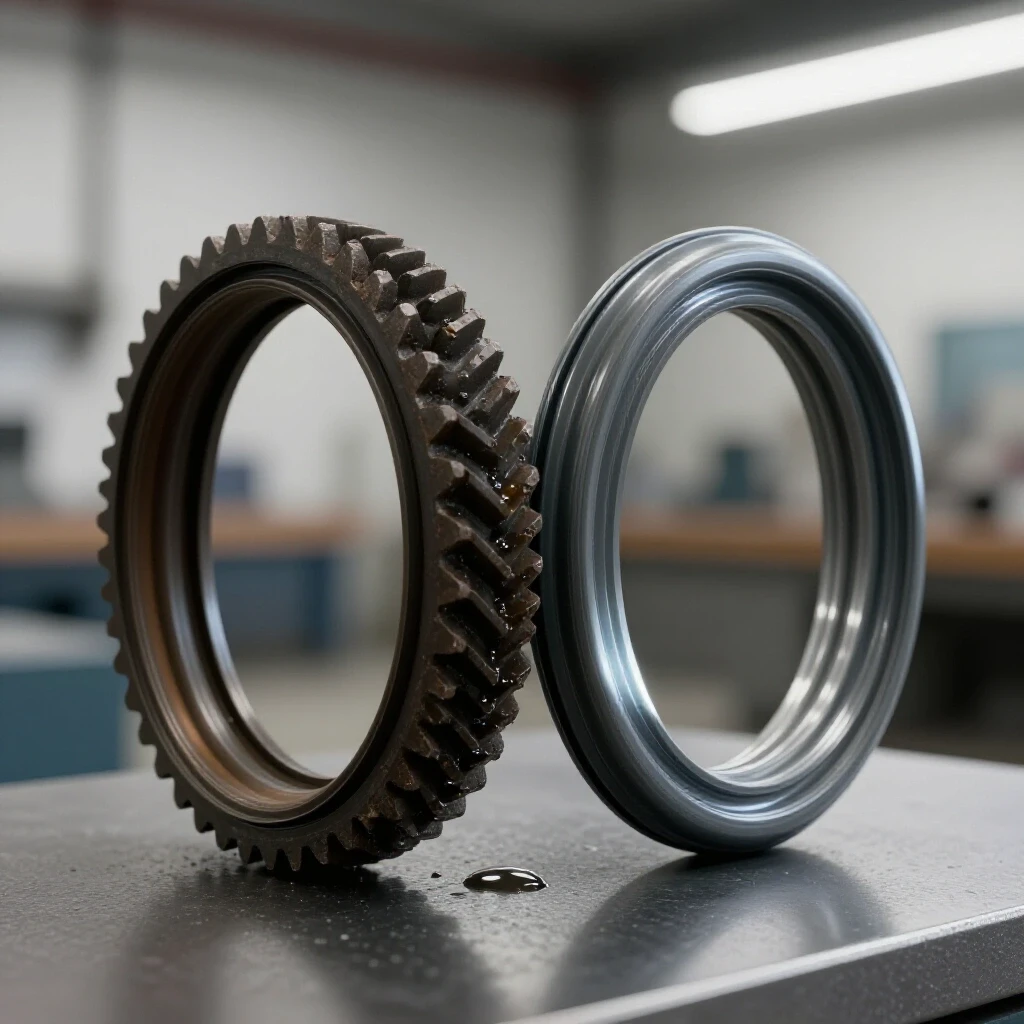
How to Build a Rigid Stand for Welding Positioners (Plan)
I have spent nearly two decades pulling pre-war lathes, rusted drill presses, and seized grinders out of damp barns and scrap heaps. There is a specific kind of silence in a machine that hasn’t moved since 1945. Breaking that silence requires more than just a wrench and some penetrating oil; it requires a foundation that can handle the weight of history. When you are working on a heavy cast-iron assembly, you cannot rely on a flimsy workbench. You need a base that offers absolute structural integrity.
Building a heavy-duty support for a rotary welding fixture is a project that mirrors the restoration of the tools themselves. It is about mass, rigidity, and the elimination of vibration. Over the last 18 years, I have learned that if your support structure flexes even a fraction of an inch, your precision goes out the window. Whether you are rebuilding a vintage headstock or welding a new flange onto a 1930s steam pipe, the physics of the base remain the same.
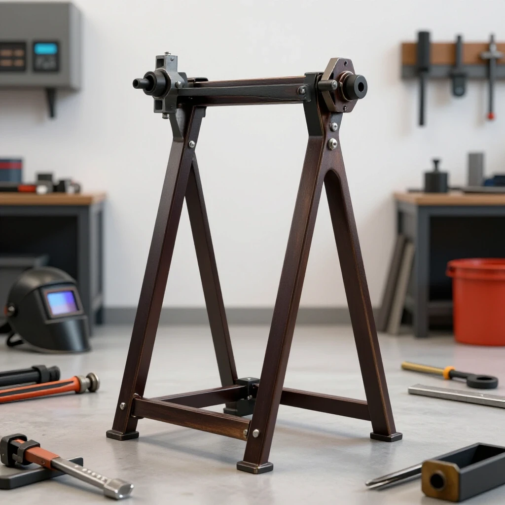
In this guide, I will walk you through the engineering principles and construction steps for a fixed, high-stiffness support system. We will focus on material selection, joint geometry, and the technical nuances of creating a low-deflection platform. This isn’t just about sticking metal together; it is about creating a tool that stays true under the torque and weight of your heaviest restoration projects.
Engineering a High-Stiffness Foundation for Rotary Fixtures
A high-stiffness foundation is a structural base designed to resist deformation and twisting when subjected to heavy loads. It ensures that the centerline of your equipment remains stable, even when a heavy workpiece is spinning or cantilevered off to one side.
When I first started restoring vintage machinery, I underestimated the power of leverage. I once mounted a medium-sized rotary table to a standard steel table. As soon as I rotated a heavy casting, the table legs flexed, and the whole assembly began to oscillate. That taught me that “strong enough” is rarely enough when dealing with the dynamic forces of rotating metal.
For a truly rigid support, you must consider the torsional rigidity of your materials. Torsional rigidity is the ability of a structure to resist twisting. In a welding environment, where heat and weight are constant factors, your base must act as an anchor. I prefer using heavy-wall square tubing over C-channel or angle iron. Square tubing has a closed profile, which makes it much more resistant to twisting forces than open profiles.
Calculating Load and Deflection
Before you cut a single piece of steel, you must understand the forces at play. You aren’t just supporting the weight of the positioner; you are supporting the weight of the workpiece and the torque generated by the rotation. If you are working on restoring classic cast iron, those pieces can be deceptively heavy. A 12-inch cast-iron pulley might look light, but it can weigh 50 pounds or more.
- Static Load: The total weight of the positioner and the heaviest part you plan to mount.
- Dynamic Torque: The force applied as the motor starts and stops rotation.
- Cantilever Force: The “pulling” force exerted on the base when the workpiece is extended away from the center of gravity.
I aim for a deflection rate of less than 0.001 inches under maximum load. To achieve this, I use a safety factor of at least 4:1. If my positioner is rated for 200 pounds, I design the stand to handle 800 pounds without showing any signs of stress.
Material Selection for Heavy-Duty Tool Supports
Material selection involves choosing specific steel grades and wall thicknesses that provide maximum mass and minimal flex. For machinery restoration work, the goal is to use materials that damp vibration and provide a stable surface for mounting precision-ground bases.
In my shop, I have a rule: if I can lift the raw material with one hand, it is probably too thin for a machine base. For a fixed-position stand, I recommend using 3-inch or 4-inch square structural tubing with a wall thickness of at least 1/4 inch (0.250″). Thin-wall tubing might be easier to weld, but it acts like a tuning fork, amplifying every vibration from the motor and the arc.
Comparing Material Profiles for Rigidity
| Profile Type | Wall Thickness | Torsional Resistance | Best Use Case |
|---|---|---|---|
| Square Tubing | 0.250″ | Excellent | Primary vertical legs and horizontal frames |
| C-Channel | 0.250″ | Moderate | Cross-bracing or secondary supports |
| Angle Iron | 0.187″ | Low | Small accessory shelves or tool holsters |
| Solid Plate | 0.500″+ | Superior | Mounting surface for the positioner base |
Using a thick top plate is non-negotiable. I typically source 5/8-inch or 3/4-inch A36 steel plate for the mounting surface. This thickness allows me to drill and tap holes for mounting bolts without worrying about the threads stripping or the plate warping during the welding process.
Managing Torque and Vibration in Fixed Bases
Managing torque and vibration involves using mass and structural geometry to absorb energy and prevent the stand from moving. This is critical when aligning classic tools, as even a tiny shimmy can lead to inaccurate measurements or poor weld penetration.
One of the biggest mistakes I see in home shops is a stand that is “top-heavy.” When you have a heavy motor and a heavy workpiece sitting three feet off the ground, the center of gravity is dangerously high. To combat this, I design the base of the stand to be wider than the top. A footprint of at least 24 inches by 24 inches is standard for a medium-duty setup.
The Role of Gussets and Bracing
Gussets are triangular pieces of plate steel used to reinforce joints. In a rigid stand, every 90-degree corner should be gusseted. This prevents the “parallelogram effect,” where the stand tries to lean to one side under a side load.
- Vertical Gussets: Place these at the junction of the legs and the floor frame.
- Top Plate Gussets: Support the corners of the mounting plate to prevent it from “diving” when a heavy part is cantilevered.
- Cross Bracing: Use 2-inch flat bar or smaller tubing to connect the legs halfway up. This breaks the “unsupported length” of the leg, significantly increasing its resistance to buckling.
Precision Alignment and Surface Preparation for Mounting
Precision alignment is the process of ensuring that the mounting surface is perfectly flat and level relative to the gravity of the earth. For machinery restorers, this often involves machine hand scraping to achieve high-precision contact points.
When you bolt a vintage cast-iron positioner to a welded steel stand, you run a risk. Heat from welding often warps the top plate. If you bolt a flat cast-iron base down to a warped steel plate, you can actually crack the casting. Cast iron is strong in compression but brittle in tension. I have seen 80-year-old castings snap because someone tightened a bolt too hard over a low spot in a mounting plate.
Hand Scraping for Flatness
To avoid cracking my vintage gear, I often use hand scraping on the top plate. This is the traditional method of removing high spots using a hand-held carbide blade. I aim for a bearing density of 10 to 20 points per inch (PPI).
- Step 1: Apply a thin layer of “Engineer’s Blue” (Prussian Blue) to a known flat surface, like a granite surface plate.
- Step 2: Lower the stand’s top plate onto the surface plate and move it slightly.
- Step 3: Flip the plate over. The blue marks show the high spots.
- Step 4: Use a scraper to shave off the blue marks.
- Step 5: Repeat until the blue marks are evenly distributed across the entire surface.
This process ensures that when the positioner is bolted down, the load is distributed evenly across the entire base, preventing internal stress and maintaining classic tool alignment.
Why Seized Cast Iron Screws Crack Under Force
When building your stand, you will likely be using heavy-duty fasteners. If you are integrating vintage parts into your build, you will encounter the nightmare of seized screws. In my 18 years of restoring machinery, I have broken my fair share of bolts.
Cast iron and steel have different rates of thermal expansion. Over decades, moisture enters the threads, creating a bond of iron oxide that is often stronger than the metal itself. If you apply a long breaker bar to a seized screw in a cast-iron housing, the screw will often shear, or worse, the casting will pull the threads out entirely.
A Real Thermal Release Plan
To safely remove stuck fasteners during your build or restoration, follow this sequence:
- Chemical Penetration: Use a 50/50 mix of Acetone and Automatic Transmission Fluid (ATF). This is a classic restorer’s secret that often outperforms commercial sprays.
- Vibration: Use an air hammer with a blunt tip on the head of the bolt. This can “shock” the rust bonds without applying rotational torque.
- Heat: Use an oxy-acetylene torch to heat the housing around the bolt, not the bolt itself. You want the hole to expand away from the fastener.
- Paraffin Wax: While the joint is hot, touch a stick of paraffin wax to the threads. The wax will wick into the microscopic gaps, providing lubrication where oils cannot reach.
Removing Machinery Rust and Preparing the Surface
Before welding your stand, you must ensure the steel is surgically clean. If you are using reclaimed steel for your project, you will likely be removing machinery rust. Rust acts as an insulator and will ruin the penetration of your welds.
I use a combination of mechanical and chemical methods. For heavy scale, a wire wheel on an angle grinder is the first step. However, for deep pits, I prefer electrolysis or evaporative chelators.
Rust Removal Method Trade-offs
| Method | Pros | Cons | Best For |
|---|---|---|---|
| Wire Wheel | Fast, inexpensive | Messy, can hide cracks | Large structural beams |
| Electrolysis | Removes rust from every crevice | Requires 12V DC setup, slow | Small vintage parts |
| Evapo-Rust | Non-toxic, safe for skin | Expensive for large parts | Precision components |
| Sandblasting | Excellent surface profile | Can warp thin sheet metal | Heavy castings |
For the stand itself, I recommend a thorough degreasing followed by a flap-disc sanding to shiny metal at every weld joint. This ensures that the structural integrity of the stand isn’t compromised by slag or inclusions.
Constructing the Main Frame: Step-by-Step
Building the frame is about maintaining squareness. In machinery restoration, we deal with tolerances of thousandths of an inch. If your stand is crooked, your equipment will never be truly accurate.
1. Cutting and Squaring
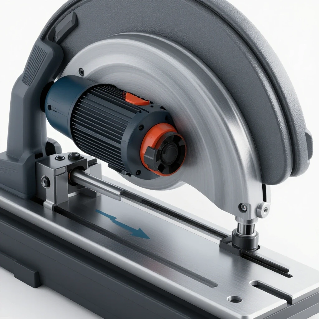
Use a cold saw or a horizontal bandsaw to ensure your cuts are perfectly 90 degrees. If you use an abrasive chop saw, the blade will likely wander, leaving you with gaps that are difficult to fill with weld. I always deburr the inside and outside of the tubing to ensure a tight fit.
2. Tacking the Base
Lay out your base frame on a flat floor. Use heavy-duty magnets or Bessey clamps to hold the pieces. Tack weld only the corners first. Check the diagonals of the rectangle; if the measurements are the same, the frame is square.
3. Vertical Alignment
When you weld the legs to the base, use a machinist’s square. Do not trust a standard carpenter’s square, as they are often out by several degrees. Tack the legs, then check them for plumb from two directions (90 degrees apart).
4. The Welding Sequence
To prevent the frame from pulling out of alignment, use a staggered welding sequence. Do not weld one joint completely before moving to the next. Instead, weld 1 inch on the front of leg A, then 1 inch on the back of leg C. This distributes the heat evenly across the structure, minimizing the “pull” that occurs as the weld pool cools and shrinks.
Managing Obsolete Fastener Patterns and Legacy Threads
If you are mounting a vintage rotary fixture to your new stand, you may find that the mounting holes don’t match modern standards. Many machines built before the 1950s used proprietary thread pitches or obsolete fastener patterns.
I keep a database of vintage thread standards, such as the Whitworth or the older ASME patterns. If the original bolts are missing, you may have to fabricate legacy parts on a lathe. For the stand, however, I recommend “standardizing” the mounting.
- Plug and Re-drill: If the original holes in the positioner base are damaged, I often plug them with a threaded cast-iron rod and re-drill for modern Grade 8 bolts.
- Adapter Plates: Build an intermediate plate. Bolt the positioner to the plate using its original hardware, then bolt the plate to your new stand using modern fasteners. This preserves the historical integrity of the tool while ensuring a secure mount.
Final Alignment and Leveling
Once the stand is welded and the top plate is prepped, you must level the entire assembly. A machine that is not level will experience uneven wear on its bearings. In the world of babbitt bearing pouring and sleeve bearing service, levelness is the difference between a machine that lasts 50 years and one that burns out in six months.
Using a Precision Level
I use a Starrett 98 machinist’s level, which is accurate to 0.005 inches per foot. A standard bubble level from a hardware store is not sensitive enough for this work.
- Place the level on the mounting plate in the X-axis.
- Adjust the feet (I use heavy-duty 3/4-inch threaded leveling pads) until the bubble is centered.
- Rotate the level 90 degrees to the Y-axis and repeat.
- Check the diagonals.
If your floor is uneven (and most shop floors are), do not just shim the legs with scrap wood. Use steel shims or dedicated leveling mounts that can be locked into place.
Safety and Structural Integrity Checklist
Before you put your restored equipment into service, go through this final checklist. I have performed this routine on every one of the 40+ pieces of machinery I have restored.
- Weld Inspection: Look for any signs of cold-lapping or undercut. If a weld looks “tall” and doesn’t blend into the base metal, it lacks penetration.
- Fastener Torque: Use a torque wrench on the mounting bolts. For a 1/2-inch Grade 8 bolt, I typically go to 80-90 lb-ft.
- Center of Gravity Check: With the positioner mounted and the heaviest workpiece attached, try to gently rock the stand. If it feels “tippy,” you need to anchor it to the floor.
- Grounding: Ensure the stand is properly grounded for welding. I like to weld a dedicated 1/2-inch brass stud to the frame for the work-clamp. This prevents the welding current from passing through the positioner’s bearings, which can cause “arcing” and ruin the bearing surfaces.
Lessons from the Shop: The Seized Shaft Incident
A few years ago, I was restoring a 1920s band saw. The main drive shaft was seized inside a pair of babbitt bearings. I had built a stand for it, but I had hurried the bracing. While I was using a hydraulic puller to remove the shaft, the stand flexed. That small movement caused the puller to slip, and the tension released all at once, nearly cracking the main frame of the saw.
That experience solidified my belief in over-building. A stand should be a “dead” object. It shouldn’t move, it shouldn’t ring, and it shouldn’t flex. When you are applying 10 tons of force to a seized part, you need to know that the ground beneath you is solid.
Maintenance and Preservation of the Stand
Once your stand is built, it needs protection. In a welding shop, “spatter” is your enemy. I always finish my stands with a high-quality machinery enamel. I prefer a “Vista Green” or “Machine Grey” to match the vintage aesthetic.
- Primer: Use a high-zinc cold galvanizing primer to prevent rust from creeping under the paint.
- Topcoat: Apply two coats of oil-resistant enamel. This makes it easy to wipe off grease and cutting fluids.
- Top Plate Protection: Never paint the actual mounting surface. Instead, keep it coated with a thin layer of paste wax or a dedicated rust preventative like Boeshield T-9. This maintains the precision-scraped surface while preventing corrosion.
Conclusion
Building a rigid support structure is the first step in a successful machinery restoration journey. It provides the safety and precision needed to handle heavy cast-iron parts and complex welding tasks. By choosing heavy-wall materials, utilizing gussets for torsional rigidity, and ensuring a flat mounting surface through hand scraping, you create a tool that will last as long as the vintage machines you are rescuing.
The next time you find a piece of “scrap” that deserves a second life, don’t just set it on a wooden bench. Build it a foundation that respects its weight and history. Start by measuring your equipment’s footprint, sourcing some 1/4-inch wall tubing, and planning your weld sequence. Your future self—and your vintage tools—will thank you.
Frequently Asked Questions
Why is wall thickness so important for a welding stand?
Wall thickness directly impacts the stiffness and vibration-damping qualities of the stand. Thin-wall tubing (like 1/8 inch) can flex under the weight of heavy machinery, leading to misalignment. A 1/4-inch wall provides the mass necessary to absorb motor vibrations and resist the torque of a rotating workpiece.
Can I use bolts instead of welding to build the stand?
Yes, you can build a bolted stand, but it requires much more effort to achieve the same rigidity. You would need to use large Grade 8 bolts and potentially “pin” the joints with dowels to prevent the frame from racking. For most restorers, a fully welded frame is superior because it becomes a single, monolithic unit.
How do I know if my mounting plate is “flat enough”?
For general welding, a plate that is flat within 1/32 of an inch is usually fine. However, for mounting vintage cast-iron equipment, you want much higher precision. If you can see light under a straightedge placed across the plate, it needs work. Ideally, you want the plate to be flat within 0.002 to 0.005 inches across its entire surface.
What is the best way to anchor the stand to a concrete floor?
I recommend using 1/2-inch wedge anchors. Drill into the concrete, insert the anchor, and tighten the nut to expand the base. This prevents the stand from walking during operation and provides extra stability when working with off-balance loads.
Should I use casters to make the stand portable?
If you need a rigid, high-precision stand, I advise against casters. Even “locking” casters have some play in the swivels and axles. If you must have mobility, use a “drop-down” caster system where the stand sits on solid feet during use and only touches the wheels when you need to move it.
How do I prevent the top plate from warping when I weld it to the frame?
Use short “stitch” welds rather than a continuous bead. Weld 1 inch, then let the metal cool until you can touch it with your bare hand before welding the next inch. This minimizes the heat-affected zone and reduces the internal stresses that cause warping.
What is the advantage of a fixed-height stand over an adjustable one?
Fixed-height stands are inherently more rigid. Adjustable stands require telescoping tubes or pins, which introduce “slop” or play into the system. For heavy-duty machinery restoration, a rock-solid, fixed base is always the safer and more accurate choice.
Is it necessary to scrape the top plate if it’s brand new?
New hot-rolled steel plate is rarely flat. It often has a “bow” from the rolling mill and is covered in mill scale. At the very least, you should grind off the mill scale and check it with a straightedge. If you are mounting a precision-ground vintage base, scraping is the only way to ensure 100% contact.
What should I do if my vintage positioner has an odd bolt pattern?
The best approach is to create a “sub-base” or adapter plate. Drill the adapter plate to match the vintage tool, then drill the stand to match the adapter plate. This avoids making unnecessary holes in your new stand and allows you to swap different tools onto the same base in the future.
How do I ground the stand for welding without damaging the positioner?
Always attach your welder’s ground clamp directly to the workpiece or a dedicated grounding lug on the stand. Never allow the current to flow through the positioner’s bearings or gears. The electrical arc can cause “pitting” on the bearing races, which will lead to premature failure of the tool.
(This article was written by one of our staff writers, Richard Beaumont. Visit our Meet the Team page to learn more about the author and their expertise.)