How to Build a Vertical Wall Holder for Bar Clamps (DIY Plan)
I remember the first time I built a heavy-duty rack for my shop. I had spent hours measuring every piece of 1.5-inch angle iron. I had my cuts down to the sixteenth of an inch. I laid it out on my bench, clamped it down, and ran a beautiful bead across the main spine. When I released the clamps, the entire frame had twisted nearly two inches out of alignment. It looked more like a piece of modern art than a functional storage fixture. That was my first real lesson in the physics of weld shrinkage and thermal expansion.
In my 13 years as a prototype technician, I have learned that custom fabrication projects are rarely about the welding itself. They are about the preparation, the layout, and the sequence. If you are building a vertical steel organizer for your heavy bar clamps, you are dealing with a lot of cantilevered weight. This means your joints must be strong, but more importantly, your frame must stay flat against the wall. If the spine warps during construction, the arms will point in different directions, and your tools will constantly slide off or bind.
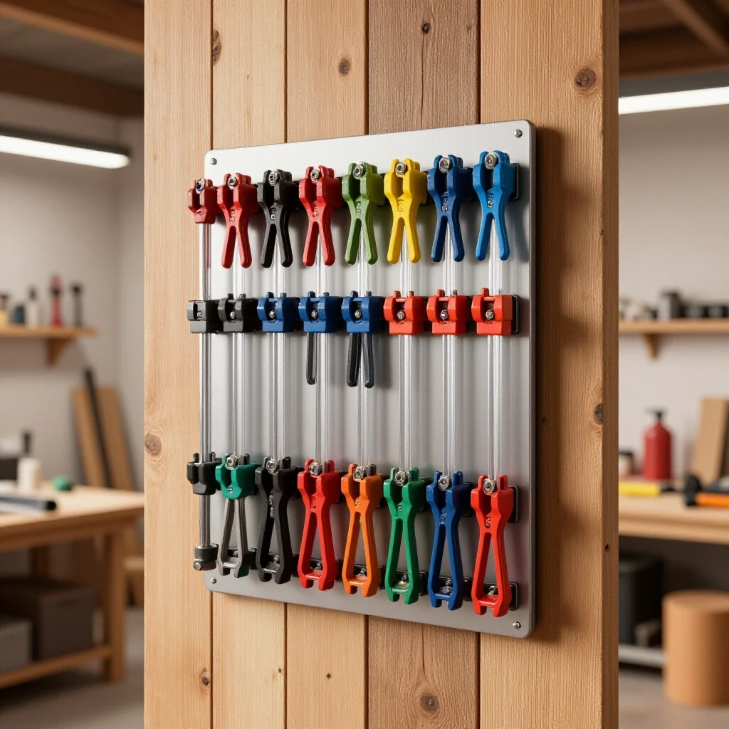
This guide focuses on the technical realities of building a robust, wall-mounted steel rack. We will cover how to account for the width of your saw blade, how to sequence your welds to fight the natural pull of cooling metal, and how to ensure your layout remains square from the first cut to the final bolt.
Planning Your Metal Cut List and Kerf Allowances
Planning ensures you do not run out of material and helps account for the kerf, which is the metal lost to the saw blade thickness. A common mistake is assuming a 20-foot stick of steel will yield exactly forty 6-inch pieces, but the blade consumes material every time it passes through.
When you start a custom fabrication project, your blueprint is only as good as your math. For a vertical storage fixture, you will likely use a long central spine with several horizontal support arms. If you are using a standard abrasive chop saw, your kerf—the width of the cut—is usually about 1/8 of an inch. If you have ten arms to cut, you are losing 1.25 inches of total material just to dust.
I always recommend creating a “cut map” before you touch the saw. Start with your longest pieces first. If you mess up a long cut, you can often salvage the material for a shorter component. For a wall rack, your spine might be 48 inches of 2-inch flat bar or square tubing. The arms might be 8-inch lengths of angle iron.
Metal Kerf Allowances by Cutter Type
| Tool Type | Average Kerf Width | Accuracy Level | Heat Affected Zone (HAZ) |
|---|---|---|---|
| Abrasive Chop Saw | 0.125″ (1/8″) | Low | High |
| Cold Saw | 0.062″ (1/16″) | High | Very Low |
| Plasma Cutter | 0.150″ – 0.200″ | Moderate | Medium |
| Band Saw | 0.035″ – 0.045″ | High | None |
| Angle Grinder (Thin) | 0.040″ – 0.060″ | Low | Medium |
Always mark your steel with a scribe or a fine-point silver pencil. A standard soapstone marker leaves a line that is nearly 1/16 of an inch wide. If you “split the line” with your blade, you are already introducing error. I prefer to mark the exact dimension and then align my blade so it consumes the material on the “waste side” of the line. This ensures the final part is exactly the length I intended.
Designing for Clamp Jaw Clearance and Weight Loads
A storage rack must account for the specific throat depth of your tools while ensuring the steel can handle the cantilevered weight without sagging. The geometry of the support arms determines how easily you can grab a tool when you are in the middle of a glue-up.
When designing a vertical storage system, you must measure the “throat” of your clamps. This is the distance from the bar to the edge of the jaw. If your support arms are too short, the jaws will hit the wall, preventing the bar from seating properly. If the arms are too long, the weight of the steel itself adds unnecessary leverage and stress to your wall anchors.
For most heavy-duty bar clamps, an 8-inch support arm made of 1/8-inch thick angle iron is sufficient. I suggest spacing the arms at least 4 inches apart vertically. This gives your hands enough room to grip the handle without barking your knuckles on the arm above it.
Consider the “Moment of Force” in your design. If you hang 50 pounds of steel clamps 8 inches away from the wall, you are creating a significant pull on the top mounting bolts. I always use a thicker gauge for the main spine—at least 3/16 inch—to prevent the spine from bowing outward under the collective weight of the tools.
Creating Accurate Layouts for Repetitive Metal Components
Layout involves marking your steel with precision using scribes or markers to ensure every support arm aligns perfectly across the main spine. When you have ten identical arms, any small deviation in the first one will be magnified as you move down the rack.
In custom fabrication projects, “stacking tolerances” is a major hurdle. If your first arm is 1/32 of an inch off, and you measure the second arm from the first one, by the time you reach the tenth arm, you could be nearly half an inch out of square. To avoid this, always measure from a single “datum point” or the very end of your spine.
- Clean the Mill Scale: Use a flap disc to remove the dark gray coating (mill scale) where your marks will go. This makes scribed lines much easier to see.
- Use a Center Punch: Once you mark the location for a support arm or a mounting hole, hit it with a center punch. This gives your drill bit or weld puddle a definitive home.
- The Square Check: Use a machinist’s square to ensure your arms are perpendicular to the spine. Do not trust the factory edge of the steel to be perfectly 90 degrees.
I like to use a layout dye, often called Dykem, on the steel. You brush it on, let it dry, and then scribe your lines through it. The bright silver of the steel pops against the blue dye, allowing for +/- 1/64-inch accuracy. For a shop fixture, this might seem like overkill, but it builds the habits necessary for high-precision work like chassis building.
Building Workshop Jigs to Maintain Squareness During Assembly
Jigs are temporary structures that hold your workpieces in a fixed position, preventing movement while you apply the first tack welds. Without a jig, the heat of the welding arc will pull the metal as it liquifies, ruining your careful layout.
You do not need an expensive 3D welding table to create a functional jig. For a vertical clamp rack, you can build a simple “L-jig” out of scrap angle iron. Clamp a straight piece of steel to your workbench to act as a fence. Then, clamp your spine against that fence.
When you are ready to attach a support arm, use a second piece of steel clamped at a perfect 90-degree angle to the spine. This creates a “pocket” where the arm can sit. This ensures that every arm is at the exact same angle.
Fixturing Span Recommendations for Steel Thickness
| Material Thickness | Maximum Unsupported Span | Clamp Spacing | Tack Weld Size |
|---|---|---|---|
| 1/16″ (16ga) | 12 inches | Every 4 inches | 1/8″ bead |
| 1/8″ (11ga) | 24 inches | Every 8 inches | 1/4″ bead |
| 3/16″ | 36 inches | Every 12 inches | 3/8″ bead |
| 1/4″ | 48 inches | Every 18 inches | 1/2″ bead |
Remember that clamps are not just for holding things still; they act as heat sinks. A heavy C-clamp attached near the weld joint will soak up some of the thermal energy, reducing the overall expansion of the workpiece. I always leave my clamps on until the metal is cool enough to touch with a gloved hand. If you release them while the metal is still glowing, the internal stresses will win, and the part will move.
Managing Thermal Distortion Through Strategic Weld Sequencing
Weld sequencing is the specific order in which you apply heat to a joint to balance the internal stresses that cause metal to warp. Metal expands when it is heated and contracts as it cools. Because it contracts more than it expands, it “pulls” the joint toward the weld.
If you weld all the support arms on the right side of the spine first, the spine will curve into a bow. To combat this, you must use a balanced sequence. Think of it like tightening the lug nuts on a car tire. You move in a cross-pattern to distribute the pressure evenly.
- Tack everything first: Put small tacks on all arms before doing any full beads.
- Alternate sides: Weld the top arm, then the bottom arm, then the middle arm.
- Back-stepping: Instead of running one long bead from left to right, start your bead an inch in from the edge and weld back toward the start. Then start another inch further and weld back to your previous starting point.
- Opposing Welds: If you weld the “front” of the arm-to-spine joint, the arm will pull upward. You must weld the “back” or the underside to pull it back into alignment.
In my experience, “chasing square” is a losing game once the metal is hot. If you see a part start to pull, stop. Let it cool completely. You can often use the cooling of the next weld to pull the part back into the correct position. This is why weld sequencing layout is the most critical skill in metal warping solutions.
Structural Tacking and Final Assembly Techniques
Tack welds are small, temporary beads that hold the structure together for a final check before the full-strength welds are applied. A good tack should be strong enough to hold the weight of the part but small enough to be easily ground away if you find an error.
For 1/8-inch steel, a tack weld should be about 1/4 inch long. I usually place tacks on the corners of the joint. For a vertical storage fixture, I place one tack on the top of the support arm and one on the bottom. I then check the arm with a square. If it is leaning, I can “cold-set” it by giving it a sharp tap with a dead-blow hammer. The tack weld will act as a hinge.
Once all the arms are tacked and the entire assembly is verified for squareness, I begin the final welding. I use a “stitch weld” approach. Instead of a continuous 2-inch bead, I might do two 3/4-inch beads with a gap in the middle. For a tool rack, this is more than enough strength and significantly reduces the total heat input into the spine.
Weld Sequencing and Distortion Control Checklist
- Verify all tacks are secure and penetrate both workpieces.
- Check the “straightedge” of the spine against a known flat surface.
- Allow at least 5 minutes of cooling time between heavy welding passes.
- Use a copper or aluminum backing bar as a heat sink if welding thin-walled tubing.
- Monitor the “angular pull” (the tendency of a T-joint to close its angle) and compensate by slightly over-bending the joint in the opposite direction before welding.
Why Weld Shrinkage Warps Square Structures
Understanding the physics of metal behavior helps you anticipate problems before they happen. When you lay down a bead of molten steel at 2,500 degrees Fahrenheit, it occupies a certain volume. As it cools to room temperature, it shrinks by about 2% to 3% in volume. This shrinkage exerts thousands of pounds of force on the surrounding cold steel.
In a T-joint—like an arm attached to a spine—the weld bead is usually on one side. As that bead shrinks, it acts like a tightening rubber band, pulling the arm toward the weld. If you aren’t careful, your 90-degree angle will quickly become 87 degrees.
To prevent this, I often “preset” my joints. I will clamp the support arm so it is at 91 or 92 degrees, leaning away from the side I plan to weld. When the weld cools and pulls the metal, it brings the arm perfectly into a 90-degree position. This takes practice to master, but it is a standard technique in professional workshop jigs and fixtures.
Secure Mounting and Load Distribution on Shop Walls
Proper anchoring involves transferring the weight of the metal rack and its contents directly into the structural studs of the building. A vertical rack full of steel clamps can easily weigh over 150 pounds. This is not a load for drywall anchors.
If you are mounting to a wood-framed wall, you must locate the center of the studs. I prefer to use 5/16-inch diameter lag bolts that are at least 3 inches long. This ensures at least 1.5 inches of thread engagement into the solid wood of the stud.
- Drill Pilot Holes: Never drive a large lag bolt into a stud without a pilot hole. It can split the wood, destroying the holding power. For a 5/16-inch bolt, use a 3/16-inch drill bit.
- Use Washers: Always use a thick flat washer between the bolt head and your steel spine. This prevents the bolt from galling the metal and distributes the clamping force.
- Level the Spine: Bolt the top hole first, but do not tighten it completely. Hang a level or a plumb bob against the spine to ensure it is perfectly vertical before drilling the remaining holes.
- Masonry Anchors: If your shop has concrete or block walls, use sleeve anchors or “Tapcon” style screws. Ensure you are at least 3 inches away from any mortar joints for maximum strength.
In my own shop, I like to mount a horizontal “stringer” of 3/4-inch plywood to the wall first, spanning three or four studs. Then, I bolt my metal rack to that plywood. This gives me more flexibility in where the rack sits and adds an extra layer of structural stability.
Correcting Heat Distortion After Welding
Even with the best sequencing, some warping is inevitable. If your spine has a slight bow after it cools, you can often correct it using “flame straightening” or mechanical force.
Mechanical correction is the simplest for DIY builders. You can place the warped spine across two blocks of wood on the floor, with the “hump” facing up. By applying pressure to the center of the hump—either with a heavy press or by carefully standing on it—you can stretch the metal back into alignment.
Flame straightening is more advanced. You use an oxy-acetylene torch to heat a small “V” shaped area on the side of the metal that needs to shrink. As the spot cools, it pulls the metal toward the heat. I don’t recommend this for your first few custom fabrication projects, as it is very easy to make the warp worse if you don’t understand the grain structure of the steel.
The best solution is always prevention. By using heavy clamps, thick heat sinks, and a patient weld sequence, you can keep your vertical storage fixture within a 1/16-inch tolerance over a 4-foot span.
Actionable Tracking Framework for Your Build
To stay organized and avoid the “inaccurate cuts” pain point, use this checklist for your next fabrication session.
- Material Inventory: Verify you have enough 1/8″ or 3/16″ steel for the spine and arms, plus 10% extra for kerf and mistakes.
- Cut List Execution: Cut the spine to length first. Deburr all edges immediately to prevent cuts to your hands and ensure better fitment.
- Layout Scribing: Mark the center point of every arm on the spine. Use a square to extend these lines across the face.
- Jig Setup: Clamp a straight reference edge to your table. Set your first arm and spine against it.
- Tack Sequence: Tack the top arm, then the bottom, then the middle. Check for square after every two tacks.
- Final Weld Log: Follow a back-stepping pattern. Do not weld more than 2 inches at a time in any one spot.
- Cooling Phase: Leave all clamps attached for at least 15 minutes post-welding.
- Mounting: Use a stud finder and 3-inch lag bolts for the final installation.
Building shop fixtures is the best way to hone your fabrication skills. Unlike a trailer or a chassis, the stakes are lower, but the physics are the exact same. Every time you successfully manage the heat of a weld to keep a project square, you are becoming a better builder.
FAQ: Frequently Asked Questions
How do I prevent the support arms from sagging over time? Sagging is usually caused by using steel that is too thin or welds that lack penetration. For a standard clamp rack, use at least 1/8-inch thick angle iron. Ensure your welder is set hot enough to “dig” into the base metal of the spine. A gusset—a small triangular piece of steel welded under the arm—can also provide massive structural support if you plan to hang exceptionally heavy clamps.
What is the best way to clean the steel before welding? Mill scale is an insulator and will cause a turbulent, weak arc. Use a 40 or 60-grit flap disc on an angle grinder to strip the steel down to shiny silver where you plan to weld. Also, wipe the area with acetone to remove any shipping oils, which can cause porosity (tiny bubbles) in your weld beads.
How many mounting holes do I need for a 4-foot vertical rack? For a 48-inch spine, I recommend at least three mounting points: one 2 inches from the top, one in the dead center, and one 2 inches from the bottom. This prevents the spine from “walking” or vibrating against the wall when you are removing or replacing tools.
Can I use a MIG welder for this project, or do I need TIG? MIG (Metal Inert Gas) is perfect for this. It is fast and provides excellent strength for structural shop fixtures. TIG (Tungsten Inert Gas) offers more control over heat, which can help reduce warping, but it is much slower. If you use MIG, just be sure to use a “stitch” technique to keep the total heat input down.
What should I do if my drill bit keeps wandering during layout? This happens because the bit is trying to find the path of least resistance on the hard mill scale. Always use a center punch to create a physical divot in the steel. Start with a small “pilot” drill bit (about 1/8 inch) before moving up to your final bolt hole size. This ensures the hole stays exactly where you marked it.
How do I calculate the total weight capacity of my rack? A single 5/16-inch lag bolt into a Douglas Fir stud has a shear strength of several hundred pounds. However, the weak point is usually the leverage on the support arm. If you use 1/8-inch steel and a 1/4-inch weld bead, each arm can easily support 50-75 pounds. The key is ensuring your wall anchors are deep enough into the wood.
Why is my metal “popping” and “spitting” while I weld? This is almost always due to contamination. If you didn’t grind off the mill scale or if there is paint or rust on the back side of the joint, the heat will vaporize those impurities, creating gas pockets. Cleanliness is 90% of a good weld.
Is it better to weld the arms on the bench or after the spine is on the wall? Always weld on a flat, grounded workbench. You need the ability to clamp the project down to a heavy surface to fight warping. Welding vertically on a wall is much more difficult and provides no way to fixture the parts for squareness.
How do I deal with “angular pull” on the support arms? Angular pull happens when the weld on top of the arm shrinks and pulls the arm upward. To fix this, you can either tack the bottom of the arm first to act as an anchor, or you can use a “strongback”—a heavy piece of steel clamped across the arms to hold them at 90 degrees while they cool.
What is the best finish to prevent rust in a garage shop? After welding and grinding your tacks smooth, wipe the whole rack down with mineral spirits. Apply a coat of self-etching primer followed by a high-quality enamel spray paint. This will prevent the humidity in your garage from turning your new fixture into a rusty mess within a few months.
(This article was written by one of our staff writers, Robert Kline. Visit our Meet the Team page to learn more about the author and their expertise.)