How to Build a Welder Ground Bus Bar on your Table (Guide)
I remember the first time I tried to weld a thin-walled square tube chassis for a custom go-kart. I had my ground clamp snapped onto a rusty corner of the table, thinking it was “good enough.” Halfway through a critical joint, the arc started sputtering and wandering like a flashlight with dying batteries. I ended up with a cold lap weld that looked like a row of grapes. That was the day I realized that a solid, reliable electrical path is just as important as the gas in my tank or the wire in my feeder.
In my 13 years as a prototype technician, I’ve learned that most “bad” welds in home shops aren’t caused by a lack of skill. They are caused by poor electrical connections. A dedicated, high-conductivity attachment point on your fabrication surface solves this by providing a clean, low-resistance path for the current to return to the machine. This project is about more than just a piece of metal; it’s about ensuring every custom fabrication project you start has the best possible chance of success.
The Role of a Centralized Work Return Path in Fabrication
A centralized work return path acts as a high-speed highway for welding current. In a typical shop, we often clip our ground clamp to whatever is closest, which might be a greasy table edge or a painted leg. This creates resistance.
Resistance in a welding circuit leads to voltage drop. When voltage drops, the arc becomes unstable, and heat input fluctuates. By installing a dedicated conductive strip—often called a bus bar—directly onto your steel workbench, you create a massive surface area for your work clamps. This ensures that no matter where you are working on the table, your machine sees a consistent, low-resistance connection. This is vital for maintaining tight dimensional tolerances because an unstable arc leads to inconsistent bead profiles and unpredictable heat-affected zones.
Why Conductivity Matters for Arc Stability
Conductivity is the measure of how easily electricity flows through a material. Steel is a decent conductor, but it isn’t great compared to copper or aluminum. When you rely solely on a steel table to carry current, you are using a material that has about 10% to 15% of the conductivity of copper.
By mounting a copper or aluminum strip to your table, you provide a “preferred path” for the current. Interestingly, this also helps prevent “arc blow,” a frustrating phenomenon where the magnetic field of the welding current pushes the arc away from your joint. A well-placed grounding hub keeps the current path predictable and straight.
Selecting Materials for High-Conductivity Attachment Points
Choosing the right material for your workshop fixtures is a balance between performance and cost. For a grounding strip, you want something that can handle high amperage without getting hot and something that won’t easily oxidize into a non-conductive mess.
I generally recommend either C110 copper or 6061-T6 aluminum. Copper is the gold standard for conductivity, but it is expensive and can be difficult to source in thick sections locally. Aluminum is more affordable and still offers significantly better conductivity than the steel of your workbench.
Comparison of Material Properties for Grounding Strips
| Material | Conductivity (% IACS) | Melting Point (°F) | Cost Factor | Best For |
|---|---|---|---|---|
| C110 Copper | 100% | 1,981 | High | High-precision TIG work |
| 6061 Aluminum | 40-45% | 1,221 | Moderate | General MIG/TIG fabrication |
| Mild Steel (A36) | 10-15% | 2,750 | Low | Structural table frames |
| Stainless Steel | 2-3% | 2,550 | Moderate | Not recommended for grounding |
Building on this, I suggest using a bar that is at least 1/4 inch thick. A thicker bar provides more “meat” for your clamps to bite into and acts as a minor heat sink, preventing the bar itself from warping during heavy use.
Planning Your Layout and Calculating Kerf Allowances
Before you pull the trigger on your saw, you need a plan. Accurate square cuts are the hallmark of a professional build. I always start by measuring the usable length of my workbench side. You want the grounding strip to be accessible but not in the way of your clamping zones.
When planning your cuts, you must account for “kerf.” Kerf is the width of the material removed by the cutting tool. If you ignore kerf, your final piece will be short by the thickness of your blade. For most DIY tools, the kerf is a significant factor in your layout.
Common Kerf Allowances by Tool Type
- Abrasive Chop Saw: 1/8 inch to 3/16 inch
- Portable Band Saw: 1/32 inch to 1/16 inch
- Cold Saw: 1/16 inch to 3/32 inch
- Plasma Cutter: 1/16 inch (depending on tip size and speed)
- Zip Disc (Angle Grinder): 1/16 inch
As a result of these variations, I always mark my “cut line” on the waste side of my measurement. If I need a 24-inch bar, I measure 24 inches, draw a line, and make sure my blade eats the material on the 24-1/16 inch side. This keeps my dimensional tolerances within +/- 1/16th of an inch.
Designing Workshop Jigs for Mounting the Bar
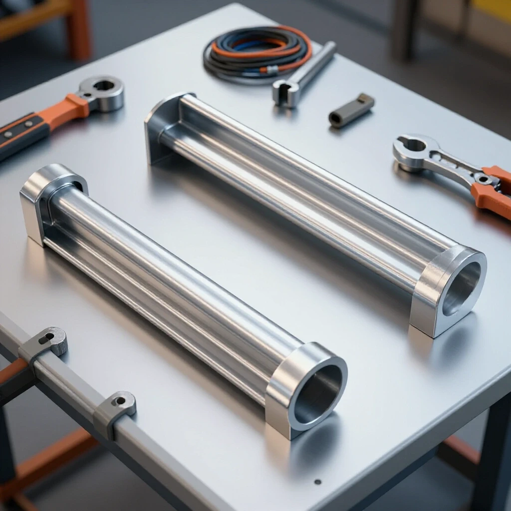
You cannot simply weld a copper or aluminum bar directly to a steel table. These metals do not bond well through traditional welding, and even if they did, the thermal expansion differences would cause the bar to pop off as it cooled. Instead, we use steel mounting tabs or “stand-offs.”
A stand-off is a small piece of steel that is welded to the table, which then holds the conductive bar in place via bolts. This creates a mechanical connection that can be disassembled for cleaning. To keep everything straight during installation, I build a simple jig using scrap angle iron. This jig holds the tabs at a consistent distance from the table edge while I tack them in place.
Fixturing Span Recommendations
When mounting a long bar, you need to space your supports correctly to prevent the bar from flexing when you tighten your ground clamp.
- 1/4″ Thick Bar: Space supports every 8 to 10 inches.
- 3/8″ Thick Bar: Space supports every 12 to 15 inches.
- 1/2″ Thick Bar: Space supports every 18 to 24 inches.
Using these metrics ensures that your conductive strip remains rigid. If the span is too wide, the bar will bow, leading to a loose electrical connection over time.
Managing Metal Warping During the Tacking Phase
Metal warping is the biggest enemy of any custom fabrication project. When you apply heat to one side of a steel plate—like your workbench—the metal expands. As it cools, it contracts, often pulling the plate into a “cup” or “bow” shape.
To combat this while installing your mounting tabs, you must use a strategic tacking sequence. A tack weld is a small, temporary weld used to hold parts in alignment. For a workbench accessory, I use tacks that are roughly 1/4 inch long.
The Science of Angular Weld Shrinkage
As a weld cools, it shrinks in all directions. Angular shrinkage occurs when the top of the weld (the face) shrinks more than the bottom (the root), pulling the two pieces toward each other. If you weld all the tabs on one side of the bar in a row, the cumulative pull will bow your table edge.
To prevent this, I use a “staggered” tacking method. I place one tack on the first tab, then move to the last tab, then the middle. This distributes the heat and balances the stresses across the length of the table.
Executing the Weld Sequence for Structural Integrity
Once your tabs are tacked and you’ve verified they are square with a machinist’s square, it’s time for the final welds. This is where most builders go wrong by laying long, continuous beads. In my experience, long beads are a recipe for distortion.
I prefer to use a “back-stepping” or “skip welding” technique. Instead of welding from left to right, you weld small segments in the opposite direction of the overall travel. This helps keep the average temperature of the workpiece lower.
Weld Sequencing and Distortion Control Table
| Sequence Type | Description | Distortion Risk | Best Application |
|---|---|---|---|
| Continuous | One long bead from start to finish | Very High | Heavy structural beams only |
| Skip Welding | Welding short sections with gaps between | Low | Thin sheet and table tops |
| Back-Stepping | Welding “backward” into the previous bead | Moderate | Long joints requiring full penetration |
| Balanced Tacking | Placing tacks in a star or opposing pattern | Minimal | Initial fit-up of all fixtures |
For our mounting tabs, I recommend two 1/2-inch welds on opposite sides of each tab. This provides more than enough strength to hold the bus bar and the weight of heavy ground clamps without introducing enough heat to warp a 3/8-inch or 1/2-inch thick table top.
Electrical Bonding and Surface Preparation
For the conductive bar to work, it must have a “metal-to-metal” connection with the table and the machine’s work lead. Paint, rust, and mill scale are insulators. If you bolt a copper bar over a painted table, you’ve just built a very expensive paperweight.
I use a flap disc (80 grit) to grind the mounting areas down to shiny, bare metal. I also do this on the underside of the conductive bar where it contacts the steel tabs.
Steps for a High-Quality Electrical Bond
- Grind to Bright Metal: Remove all mill scale from the steel tabs.
- Clean the Bar: Use a stainless steel wire brush on aluminum or copper to remove oxides.
- Apply Conductive Grease: Interestingly, using a specialized electrical joint compound (like Noalox) can prevent future oxidation between the different metals.
- Torque the Bolts: Use Grade 5 or Grade 8 bolts and tighten them firmly to ensure a gas-tight seal at the connection point.
Maintaining Your Workshop Jigs and Fixtures
After the build is complete, the work doesn’t stop. Copper and aluminum will naturally oxidize over time. Aluminum forms a thin, hard layer of aluminum oxide, which is actually an electrical insulator. If your arc starts to get “crunchy” or unstable again after a few months, it’s time for maintenance.
I keep a dedicated red Scotch-Brite pad near my table. Every few weeks, I give the grounding bar a quick once-over to knock off any surface oxidation or welding spatter. This simple habit keeps my arc starts crisp and my penetration consistent.
Post-Build Alignment Log
I recommend keeping a small notebook in the shop to track how your fixtures perform. After your first few projects using the new grounding system, ask yourself: * Did the arc remain stable at high amperages? * Is there any discoloration (heat) at the bolted connections? * Did the table top stay flat within my +/- 1/16th inch tolerance?
If you notice the bolts getting hot, it means you have high resistance, and you need to take the bar off and clean the contact surfaces again.
Correcting Minor Heat Distortion
Even with the best sequencing, you might notice a slight “pull” in your table edge. If the distortion is minor (less than 1/16th of an inch over 4 feet), it often doesn’t affect general fabrication. However, if you need the table perfectly flat for a custom chassis build, you may need to perform “flame straightening.”
Flame straightening involves heating a small spot on the opposite side of the warp. As that spot cools, it shrinks and pulls the metal back toward flat. This is an advanced technique that requires patience and a “less is more” approach. I usually suggest living with minor warps rather than risking making them worse with a torch.
Final Assembly Checklist
Before you call the project finished, go through this checklist to ensure everything is structurally sound and electrically efficient.
- Check for Square: Use a framing square to ensure the bar is parallel to the table edge.
- Verify Continuity: If you have a multimeter, check the resistance between the bar and the far end of the table. It should be near zero ohms.
- Inspect Welds: Look for any cracks or “undercut” in the mounting tabs.
- Clamp Test: Attach your heaviest work clamp. The bar should not flex or move.
- Clearance Check: Ensure the bar doesn’t interfere with your miter saw swing or any other tools mounted to the bench.
By following these steps, you’ve created a professional-grade grounding hub that will improve the quality of every weld you lay. It’s a small investment in material and time that pays dividends in the form of fewer failed welds and less frustration.
Frequently Asked Questions
Why can’t I just weld the copper bar to my steel table? Copper and steel have vastly different melting points and atomic structures. They do not form a reliable metallurgical bond with standard welding processes. Additionally, copper acts as a massive heat sink, making it nearly impossible to get the steel hot enough to fuse without specialized equipment.
Will an aluminum bar melt if I weld at high amperages? While aluminum has a lower melting point than steel, the bar itself isn’t part of the arc. It is only carrying the return current. As long as your connections are tight and the bar is thick enough (1/4″ or more), the electrical resistance is low enough that the bar will stay cool to the touch.
How do I prevent “galvanic corrosion” between the copper and steel? Galvanic corrosion happens when two dissimilar metals touch in the presence of moisture. In a dry garage, this is rarely an issue. However, using a conductive joint compound (anti-seize or Noalox) at the bolted joints creates a barrier against moisture and prevents the metals from reacting.
What is the best way to cut a thick copper bar without a cold saw? A standard circular saw with a carbide-tipped “non-ferrous” blade works surprisingly well for copper and aluminum. Just be sure to secure the workpiece firmly and wear full face protection, as the metal chips are hot and fly everywhere.
Can I use a stainless steel bar instead? I strongly advise against it. Stainless steel is a poor conductor—about five times worse than mild steel. Using stainless would actually increase the resistance in your circuit, defeating the entire purpose of the project.
How many mounting tabs do I really need? For a 4-foot bar, four tabs are usually sufficient. This provides a support every 16 inches. If you plan on using very heavy, high-pressure spring clamps, you might want to add a fifth tab in the center to prevent any chance of bowing.
Does the bar need to be the full length of the table? Not necessarily. A 24-inch to 36-inch section is usually plenty for most DIY projects. Place it in the area where you do 80% of your welding, typically the center-front or a specific “clean zone” on your bench.
Should I paint the mounting tabs? You can paint the sides of the tabs to prevent rust, but never paint the top surface where the bar sits or the area where the tab meets the table. Those surfaces must remain bare metal for electrical flow.
What size bolts should I use? I recommend 3/8-inch or 1/2-inch bolts. Smaller bolts (like 1/4-inch) can be snapped easily if you over-tighten them, and they don’t provide as much clamping force to ensure a low-resistance connection.
How do I know if my ground is actually better? You will notice it immediately in your arc start. A good ground allows the high-frequency start (on TIG) or the short-circuit (on MIG) to happen instantly without “stuttering” or sticking. Your welds will also have a more consistent “sizzle” sound.
Can I use this for a plasma cutter too? Absolutely. Plasma cutters are even more sensitive to ground quality than welders. A solid return path will help your plasma electrode last longer and result in cleaner, dross-free cuts.
Is it okay to mount the bar vertically on the side of the table? Yes, mounting it to the side “apron” of the table is a great way to keep the top surface clear for your workpieces while still keeping the grounding points within easy reach. Just ensure the tabs are welded securely to the main frame of the table.
(This article was written by one of our staff writers, Robert Kline. Visit our Meet the Team page to learn more about the author and their expertise.)