How to Calibrate and Check Your Shop Layout Tools (DIY Fix)
In my fourteen years of navigating the grit and sparks of fabrication shops, I have learned that the most dangerous tool in the building isn’t the plasma cutter or the 50-ton press brake. It is a square that isn’t square. I have stood over structural frames that failed load tests, not because the welder lacked skill, but because the initial layout was off by a fraction of a degree. That tiny gap, often hidden by a heavy weld bead, creates an uneven load path that can lead to catastrophic structural failure.
When you are building a trailer, a gantry crane, or even a heavy-duty workbench, you are managing physical forces that do not forgive. If your layout tools are lying to you, your entire project is built on a foundation of hidden stress. I remember an early project where I was fabricating a support bracket for a hydraulic press. I trusted my framing square implicitly. Because the square was out of true, the joint fitment was poor. To compensate, I “filled the gap” with extra weld passes. The resulting heat affected zone weakness—the area of metal around the weld that becomes brittle due to excessive heat—caused the bracket to snap under a 5:1 safety load. That day, I stopped trusting my tools and started verifying them.
The Physics of Precision in Structural Layout
Structural integrity begins with the geometry of the joint. When metal components do not meet at the intended angles, the distribution of weight becomes unpredictable. Instead of a direct compression load, you introduce shear stress—a force that tries to slide one layer of material past another. If your layout tools lead to misaligned joints, you are essentially pre-loading the structure with internal tension before it ever sees its first real weight.
Tensile Strength is the maximum amount of pulling stress a material can withstand before failing. In a perfectly aligned joint, the load is distributed evenly across the weld throat. However, a layout error of just two degrees can reduce the effective load capacity of a joint by nearly 30% because the force is no longer axial. This is why verifying the accuracy of your measuring and marking equipment is a non-negotiable part of garage fabrication safety.
| Layout Error (Degrees) | Load Path Deviation | Potential Strength Reduction | Recommended Safety Factor |
|---|---|---|---|
| 0.1° | Negligible | < 2% | 2:1 |
| 0.5° | Minor Eccentricity | 5–10% | 3:1 |
| 1.0° | Moderate Shear | 15–20% | 4:1 |
| 2.0°+ | Critical Misalignment | 30%+ | Redesign Required |
Validating Squareness Without Professional Metrology
A square is the backbone of any structural build. Whether it is a small machinist square or a large framing square, its job is to ensure that vertical and horizontal members transfer loads correctly. Over time, dropping a square or even the vibration of a busy shop floor can knock these tools out of alignment. You don’t need a lab to check this; you only need a straight edge and a scribing tool.
The “Flip Test” is the most reliable DIY method for verifying a square. You take a piece of plate steel with one perfectly straight edge. Place the square against that edge and scribe a fine line. Then, flip the square over so the same side of the blade is now facing the opposite direction. Align it with the bottom of your scribed line. If the blade does not perfectly match the line all the way to the top, your tool is inaccurate.
- Step 1: Secure a flat piece of scrap with a factory-milled edge.
- Step 2: Use a sharp scribe to draw a line perpendicular to that edge.
- Step 3: Flip the square 180 degrees.
- Step 4: Measure the deviation at the tip of the blade.
If you find an error, you can often “tune” a steel square using a center punch. If the angle is too closed (less than 90 degrees), use a center punch to create a series of small indentations near the inside corner of the “L.” This moves a tiny amount of metal and opens the angle. If the angle is too open, punch near the outside corner. This is a slow, methodical process that requires re-testing after every few strikes.
Why Straightedge Accuracy Prevents Weld Defects
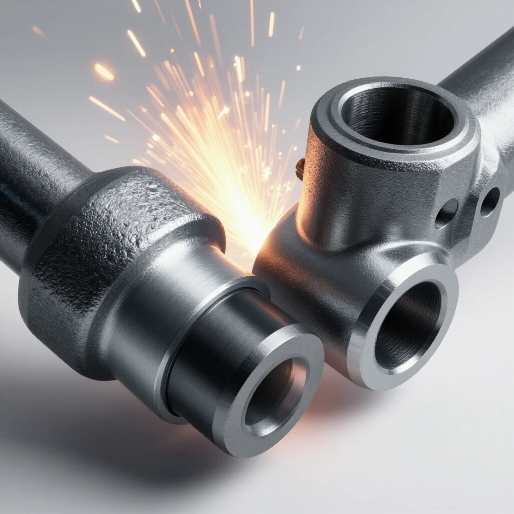
A straightedge is used to check the flatness of mating surfaces and the straightness of long structural members. If your straightedge is bowed, you will end up with “daylight” in your joints. This leads to poor fitment, which is a primary cause of welding defect troubleshooting issues like burn-through or excessive porosity.
When gaps are inconsistent, the welding gas flow rate (which should stay between 15–20 CFH) cannot properly shield the molten puddle. The air pulled into those gaps causes oxidation and internal voids. To check a straightedge, use the “Line of Sight” method or the “Three-Edge Comparison.” If you have three straightedges, compare A to B, B to C, and C to A. If they all match perfectly with no light passing between them, they are straight. If only two match, one is likely concave and the other convex.
- Visual Inspection: Look down the edge like a rifle sight to spot obvious bows.
- Feeler Gauge Test: Place the straightedge on a surface plate (or a thick piece of cold-rolled steel) and try to slide a 0.002-inch feeler gauge underneath.
- The Reversal Method: Draw a line along the edge, flip it end-over-end, and see if the edge still tracks the line.
Leveling and Plumb Verification for Heavy Frames
In structural work, “level” and “plumb” are not just suggestions; they ensure that gravity pulls the load straight down through the center of your support columns. A level that is off by 1/16th of an inch over four feet can result in a massive lean at the top of a ten-foot pillar. This creates a “moment arm” that puts unnecessary bending stress on the base welds.
To verify a bubble level, use the 180-degree reversal check. Place the level on a reasonably flat surface and note the bubble’s position. Then, rotate the level 180 degrees horizontally so the ends switch places. If the bubble does not land in the exact same spot, the vial is out of calibration. Many professional-grade levels have adjustment screws for the vials, but for fixed-vial levels, you must mark the error or replace the tool.
Precision Marking and Parallax Error Prevention
Even with calibrated tools, human error during the marking phase can compromise a build. Parallax error occurs when you view your marking tool from an angle, causing you to misplace the line by a fraction of an inch. In my shop, I use a workshop safety checklist that includes verifying my marking points under direct vertical light.
Using a thick carpenter’s pencil for structural steel layout is a mistake I see often. A pencil line can be 1/16th of an inch wide. If you cut on the wrong side of that line, and your partner does the same on the matching piece, you now have an 1/8th-inch gap. This gap requires more filler metal, leading to higher heat input and a larger heat affected zone weakness. Always use a tungsten carbide scribe or a fine-point silver streak pencil for high-accuracy layout.
Joint Preparation and Load Path Analysis
Once your tools are verified, the next step is ensuring the joint itself is prepared to handle the calculated load. A common error is underestimating the importance of the “root opening”—the gap between two pieces of metal before welding. If your calibrated square shows a perfect 90-degree fit, but your cut is jagged, the weld will not penetrate deeply enough.
Shear Stress is particularly dangerous in lap joints. If the layout isn’t precise, the weld might only grip the surface of the metal, leading to a “brittle fracture” where the weld snaps off the base metal under load. To prevent this, I always aim for a safety margin of at least 3:1 for non-critical structures and 5:1 for anything overhead.
- Clean the Surface: Remove mill scale and rust at least one inch back from the joint.
- Check Fitment: Ensure there is no “daylight” in the root of the joint.
- Tack Weld Strategically: Use small tacks to hold the alignment before committing to a full bead.
- Re-Verify Squareness: Heat causes metal to pull; check your angles after the first few tacks.
Managing Material Distortion and Heat
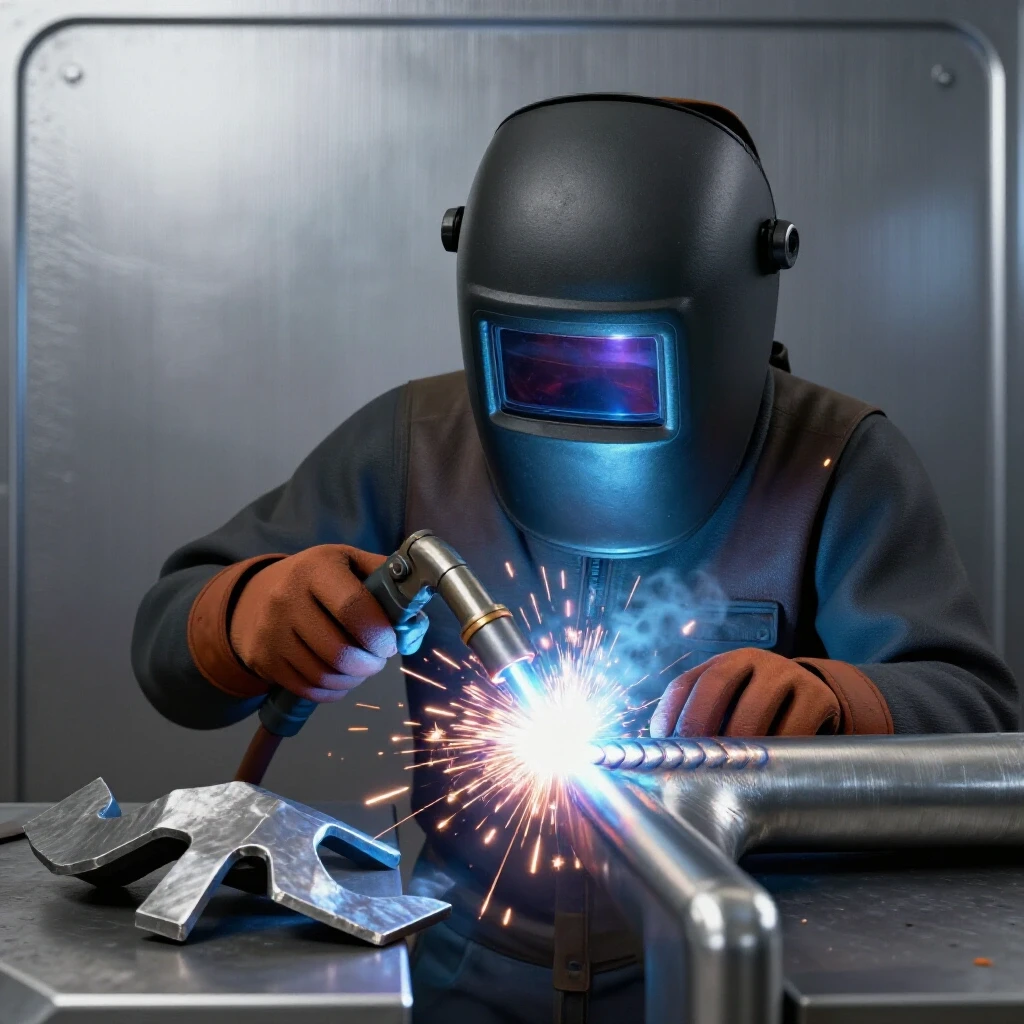
Every time you strike an arc, you are introducing localized heat that wants to warp your perfectly laid-out project. This is where many fabricators lose their accuracy. You can have the most precisely calibrated tools in the world, but if you don’t manage heat, the metal will move.
The heat affected zone weakness is a real threat to structural integrity. As the metal cools, it contracts and pulls the joint toward the weld. To combat this, I often “preset” my joints. If I know a weld will pull a vertical post inward by one degree, I will use my calibrated square to set the post one degree “out” before welding. As the weld cools, it pulls the post into a perfect 90-degree angle.
- Weld Sequencing: Move around the project rather than welding one side completely.
- Backstepping: Weld in short sections in the opposite direction of the overall travel.
- Heat Sinks: Use heavy copper or aluminum blocks to soak up excess heat near the joint.
Essential DIY Verification Toolkit
You do not need to spend thousands of dollars to ensure your shop is accurate. A few key items, used correctly, will provide the data you need to build safely.
- A Known Straightedge: A piece of cold-rolled flat bar, verified by the three-edge method.
- Feeler Gauges: Essential for measuring small gaps in tool-to-surface checks.
- Tungsten Carbide Scribe: For making lines that have almost zero width.
- Center Punch: Used for both marking and “tuning” the angles of steel squares.
- Plumb Bob: Gravity is the ultimate constant; a plumb bob never needs calibration.
Case Study: The 1/8-Inch Failure
I once consulted on a project involving a heavy-duty engine hoist. The builder used a framing square that had been dropped. The square was out by about 1/16th of an inch over its 24-inch length. By the time the hoist arm reached its full six-foot extension, that error had multiplied. The arm was nearly half an inch off-center.
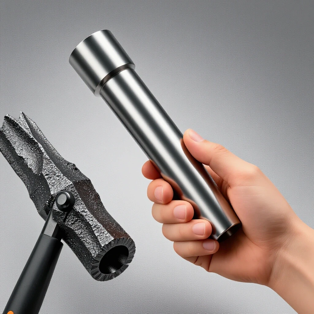
When the hoist picked up a heavy diesel engine, the load wasn’t centered over the base. This created a twisting force (torsion) that the vertical mast wasn’t designed to handle. The mast buckled at the base, precisely at the heat affected zone weakness created by the oversized welds used to fill the original gaps. The engine hit the floor, and the hoist was a total loss. All of this was preventable with a five-minute flip-test on a ten-dollar square.
Establishing a Monthly Shop Audit
Accuracy is not a one-time event; it is a habit. I recommend a monthly audit of your most-used layout tools. This keeps your mind sharp and your projects safe.
- Week 1: Check all squares using the flip-test.
- Week 2: Verify levels and plumb bobs.
- Week 3: Inspect straightedges and measuring tapes (check for hooked ends that have become loose).
- Week 4: Clean and calibrate marking tools and check welding gas flow rate regulators.
By following this routine, you eliminate the “uncertainty factor” from your builds. You can trust that when your square says 90 degrees, it truly is 90 degrees. This allows you to focus on your welding technique and structural design, knowing your foundation is solid.
Frequently Asked Questions
How can a dropped square affect the safety of a heavy build? A dropped square often develops a tiny burr or a slight bend at the corner. This causes the tool to sit “cocked” against your workpiece. Even a 0.5-degree error can lead to significant misalignment in large frames, creating unintended shear stress on your welds.
What is the easiest way to check a tape measure for accuracy? Tape measures have a sliding hook at the end to account for the thickness of the hook itself during “inside” and “outside” measurements. If the rivets become too loose or the hook gets bent, your measurements will be off. Check it against a high-quality steel ruler; the one-inch mark on the tape should align perfectly with the one-inch mark on the ruler.
Can I fix a level if the bubble is no longer accurate? If the level has adjustment screws, you can calibrate it by placing it on a surface, noting the bubble, flipping it 180 degrees, and adjusting the screws until the bubble sits in the same relative position in both directions. If it is a fixed-vial level, it generally cannot be repaired and should be relegated to non-critical tasks.
Why does “filling a gap” with a weld lead to structural failure? Filling a large gap requires more heat and more weld metal. This significantly expands the heat affected zone weakness, making the surrounding base metal more brittle. Furthermore, large gaps often result in “lack of fusion” at the root of the weld, which is a hidden defect that can trigger a crack under load.
How do I know if my straightedge is “straight enough” for fabrication? For most structural fabrication, a deviation of less than 0.005 inches over four feet is acceptable. If you can see light between your straightedge and a known flat surface, or if a thin feeler gauge slides through, the tool needs to be marked as “rough use only” or corrected.
Is there a way to check squareness on very large projects where a framing square is too small? Yes, use the 3-4-5 rule (Pythagorean theorem). Measure 3 feet along one side and 4 feet along the other. The diagonal distance between those two points must be exactly 5 feet. For even greater accuracy, use multiples like 6-8-10.
What is parallax error, and how do I avoid it during layout? Parallax error happens when your eye is not directly above the marking tool, causing the line to appear shifted. To avoid this, always look straight down at your scribe and workpiece, and use a thin marking tool like a scribe rather than a thick pencil.
How often should I check my shop layout tools? I recommend a quick check before starting any major structural project and a thorough audit of all tools once a month. If a tool is dropped or subjected to extreme heat, verify it immediately before the next use.
Does temperature affect the accuracy of my layout tools? Yes, metal expands and contracts with temperature. While this is usually negligible for hobbyist projects, if you are working in an unheated shop in winter and then move to a hot environment, your measurements can shift slightly. Always try to calibrate and use your tools at a consistent temperature.
Can I use a plumb bob to check my squares? Absolutely. If you hang a plumb bob, it creates a perfectly vertical line. You can place your square against the string (without touching it and causing it to swing) to check the vertical accuracy of your tool. This is an excellent way to cross-verify your level and your square at the same time.
(This article was written by one of our staff writers, James Harlan. Visit our Meet the Team page to learn more about the author and their expertise.)